CBE Manual - Electromach BV
CBE Manual - Electromach BV
CBE Manual - Electromach BV

Create successful ePaper yourself
Turn your PDF publications into a flip-book with our unique Google optimized e-Paper software.
<strong>Electromach</strong> member of the R.STAHL Technology Group<br />
OPERATING INSTRUCTIONS<br />
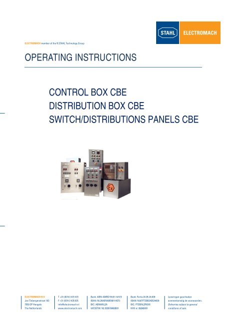
CONTROL BOX <strong>CBE</strong><br />
DISTRIBUTION BOX <strong>CBE</strong><br />
SWITCH/DISTRIBUTIONS PANELS <strong>CBE</strong><br />
<strong>Electromach</strong> B.V.<br />
Jan Tinbergenstraat 193<br />
7559 SP Hengelo<br />
The Netherlands<br />
T +31 (0)74 2 472 472<br />
F +31 (0)74 2 435 925<br />
info@electromach.nl<br />
www.electromach.com<br />
Bank: ABN-AMRO 59.01.14.573<br />
IBAN: NL29ABNA0590114573<br />
BIC: ABNANL2A<br />
VAT/BTW: NL 003578458B01<br />
Bank: Fortis 24.35.24.439<br />
IBAN: NL67FTSB0243524439<br />
BIC: FTSBNL2RXXX<br />
KVK nr: 06040491<br />
Leveringen geschieden<br />
overeenkomstig de voorwaarden.<br />
Deliveries subject to general<br />
conditions of sale.
INDEX<br />
APPLICATION.................................................................................................................................................... 3<br />
PURPOSE OF THESE INSTRUCTIONS .......................................................................................................... 3<br />
1 SAFETY INSTRUCTIONS .............................................................................................................................. 4<br />
1.1 CONFORMITY TO STANDARDS ........................................................................................................... 4<br />
2 TECHNICAL DATA ......................................................................................................................................... 6<br />
3 MOUNTING ..................................................................................................................................................... 7<br />
3.1 MECHANICAL INFORMATION ............................................................................................................... 7<br />
4 INSTALLATION .............................................................................................................................................. 9<br />
4.1 BACK-UP FUSE ....................................................................................................................................... 9<br />
4.2 INTERNAL WIRING ................................................................................................................................. 9<br />
4.2.1 CABLES ............................................................................................................................................ 9<br />
4.2.2 CABLE RUNNING ............................................................................................................................ 9<br />
4.2.3 INTRINSICALLY SAFE CIRCUITS ................................................................................................. 9<br />
4.2.4 TERMINAL BLOCKS ..................................................................................................................... 10<br />
4.2.5 EXTERNAL-CABLING ................................................................................................................... 11<br />
4.2.6 EARTHING-CONDUCTOR ............................................................................................................ 11<br />
5 COMMISSIONING ......................................................................................................................................... 13<br />
6 REPAIRS AND MAINTENANCE ................................................................................................................. 14<br />
7 ACCESSORIES / SPARE ............................................................................................................................. 17<br />
8 DISPOSAL ..................................................................................................................................................... 17<br />
9 EC-TYPE EXAMINATION CERTIFICATE ................................................................................................... 18<br />
10 DECLARATION OF CONFORMITY .......................................................................................................... 21<br />
PAGE 2/ 21
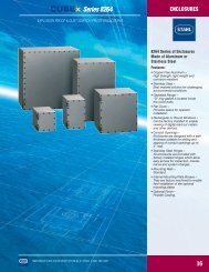
APPLICATION<br />
Type <strong>CBE</strong> control and distribution boxes and switch and distribution panels are used, together with the<br />
equipment fitted in them, to control, switch and conduct electrical energy. These enclosures are intended<br />
for local mounting as standard.<br />
PURPOSE OF THESE INSTRUCTIONS<br />
Working in hazardous areas, the safety of personnel and plant depends on complying with all relevant<br />
safety regulations.<br />
Assembly and maintenance staff working on installations therefore have a particular responsibility. They<br />
require precise knowledge of the applicable standards and regulations.<br />
These instructions give a brief summary of the most important safety measures. They supplement the<br />
corresponding regulations which the staff responsible must study.<br />
PAGE 3/ 21
1 SAFETY INSTRUCTIONS<br />
Use the enclosures only for their intended purpose.<br />
Incorrect or impermissible use or non-compliance with these instructions invalidates our warranty<br />
provision.<br />
No changes to the enclosures impairing their explosion protection are permitted.<br />
Mount the enclosures only if they are clean and undamaged.<br />
Observe the following when using the enclosures:<br />
<br />
<br />
<br />
<br />
<br />
<br />
<br />
national safety regulations;<br />
national accident prevention regulations;<br />
national installation regulations;<br />
(e.g. IEC 60079-14)<br />
generally recognized technical regulations;<br />
safety guidelines in these operating instructions;<br />
characteristic values, rated operating conditions, temperature class and explosion protection on<br />
the rating and data plates;<br />
additional instruction plates on the enclosures.<br />
Combined switch panels may only be operated with enclosures fully closed.<br />
Any damage can invalidate the Ex-protection.<br />
If required, we will provide a copy of the EC Type-Test Certificate with the relevant annex.<br />
1.1 CONFORMITY TO STANDARDS<br />
The enclosures comply with the following standards and regulations:<br />
Directive 94/9/EC<br />
EN 50014, EN 50017, EN 50018,<br />
EN 50019, EN 50020, EN 50028,<br />
EN 50281-1-1<br />
PAGE 4/ 21
Equivalent international standards:<br />
IEC 60079-0 (1998)<br />
IEC 60079-1 (2001)<br />
IEC 60079-2 (2001)<br />
IEC 60079-5 (1997)<br />
IEC 60079-7 (1990)<br />
IEC 60079-11 (1991)<br />
IEC 60079-18 (1992)<br />
IEC 61241-1 ( )<br />
EN 60947-1<br />
EN 60439-1<br />
Type <strong>CBE</strong> enclosures are suitable for use in hazardous areas, zones 1, 2, 21 and 22.<br />
PAGE 5/ 21
2 TECHNICAL DATA<br />
Explosion protection<br />
II 2GD EEx e. II. T.<br />
Test certificate KEMA 02 ATEX 2273<br />
Material<br />
Sheet steel (galvanized and painted) or stainless<br />
sheet steel<br />
Degree of protection to IEC/CEI 60529<br />
max. IP 66 (dependent on fittings)<br />
The devices fitted to type <strong>CBE</strong> enclosures differ according to customers’ requirements.<br />
Please also observe the operating instructions for these.<br />
The devices fitted determine the electrical data. Please observe the values on their type<br />
and rating plates.<br />
Working temperature range<br />
- 20 C ... + 55 C<br />
If the ambient temperature < - 20 oC, then either special „low temperature“ cable glands<br />
must be used or the enclosure must be so mounted that the cable glands are mechanically<br />
protected.<br />
Rated operating voltage<br />
Connection cross-section<br />
Rated current<br />
max. 11 kV<br />
max. 300 mm²<br />
max. 1250 A<br />
Please consult the manufacturer if operating conditions are non-standard.<br />
PAGE 6/ 21
3 MOUNTING<br />
3.1 MECHANICAL INFORMATION<br />
Mechanical details relating to fixing point positions, tolerances or weight of combined switch panels can be<br />
obtained from the construction drawing enclosed.<br />
When explosion-protected electrical equipment is exposed to the weather, it is advisable to provide a<br />
protective cover or wall.<br />
To avoid condensation forming in the metal enclosure, we recommend using a breather. It<br />
should be noted however, that this can result in a reduction in the degree of protection to<br />
IEC 60529, depending on where the breather is mounted.<br />
Transport and storage is only permitted in the original packaging.<br />
PAGE 7/ 21
1) WELDSTUDS M8x15 ON REARSIDE CAN BE USED FOR FRAMEMOUNTING<br />
To securely fix the enclosures marked with *), use either the lugs supplied or the tapped holes in the<br />
enclosure base.<br />
PAGE 8/ 21
4 INSTALLATION<br />
To avoid moisture and dirt collecting inside the combined switch panels, electrical<br />
installation must be carried out in a clean and dry environment. The enclosures may only<br />
be opened to carry out installation work and must be carefully closed again following<br />
completion of the work.<br />
4.1 BACK-UP FUSE<br />
The system must be protected by the back-up fuse specified. The fuse rating must be such that it blows<br />
when an appropriate system short-circuit current occurs.<br />
4.2 INTERNAL WIRING<br />
4.2.1 CABLES<br />
Cables of the following types only may be used for internal wiring of the control or distribution panels:<br />
H 05 V 2 for T6)<br />
H 07 G for T5) - or equivalent.<br />
Minimum cross-section 1.5 mm2 copper.<br />
4.2.2 CABLE RUNNING<br />
The cables must be run such that the leakage and air distances necessary for EEx “e“ are maintained.<br />
To facilitate orderly cable connection, the mounting rails and components may be loosened. They must<br />
however be fully tightened again when connections have been made.<br />
4.2.3 INTRINSICALLY SAFE CIRCUITS<br />
Only insulated cables whose test voltage is at least AC 500 V and whose quality is at least H05 may be<br />
used for intrinsically safe circuits.<br />
The diameter of individual conductors may not be less than 0.1 mm. This also applies to the individual<br />
wires of multi-strand cables.<br />
PAGE 9/ 21
With regard to the insulation and separation of terminals and cables, it should be noted that the insulation<br />
test voltage is derived from the sum of the rated operating voltages of intrinsically safe and non-intrinsically<br />
safe circuits.<br />
In the case of „intrinsically safe against earth“ then the insulation voltage value is at least 500 V (or double<br />
the value of the intrinsically safe circuit rated operating voltage).<br />
In the case of „intrinsically safe against non-intrinsically safe“, then the insulation voltage value is at least<br />
1500 V (or double the rated operating voltage plus 1000 V).<br />
Cables for EEx „i “ circuits must be run at least 8 mm away from the cables of other intrinsically safe<br />
circuits.<br />
The only exception to this is the use of cables in which the cores of the intrinsically safe or the nonintrinsically<br />
safe circuit are surrounded by an earthed screen.<br />
The pre-conditions for the separation between parts to be connected for intrinsically safe and nonintrinsically<br />
safe circuits are:<br />
<br />
<br />
a distance of 50 mm around an insulating (> 1 mm thick) or earthed metal (> 0.45 mm thick)<br />
isolating plate<br />
or<br />
an isolating plate which is separated from enclosure walls by a distance<br />
< 1.5 mm.<br />
4.2.4 TERMINAL BLOCKS<br />
Only 1 cable may be connected per individual terminal. Links may only be made using original Exaccessories.<br />
Any isolating plates necessary may be fitted later.<br />
Please take note of the terminal test certificate!<br />
If additional protection against cable end splaying is necessary, then end-sleeves or lugs must be used. If<br />
end-sleeves are used, it is vital that these are gas-tight and fitted with the correct tool.<br />
PAGE 10/ 21
The cross-section of such additional devices used must match that of the cable.<br />
4.2.5 EXTERNAL-CABLING<br />
Connecting cables must be led through the cable glands into the connection chamber complete with their<br />
external insulation. This means that care must be taken to ensure that the external diameter of the cable<br />
matches the clamping cross-section specified for the cable gland.<br />
To ensure that the connection chamber is fully sealed and all connections protected from strain, the<br />
hexagonal nuts of the cable glands must be fully tightened.<br />
The cables must be run in the connection chamber such that the minimum permissible bending radius for<br />
each cross-section is not exceeded and mechanical damage to cable insulation from sharp edges or<br />
moving metal parts is avoided.<br />
Please observe the following points:<br />
<br />
<br />
<br />
<br />
Connections must be made with special care;<br />
The conductor insulation must reach to the terminal. The conductor itself must not be damaged<br />
(nicked) when removing the insulation;<br />
Ensure that the maximum permissible conductor temperatures are not exceeded by suitable<br />
selection of cables and means of running them (avoid bunched cables);<br />
The permissible ambient temperature of the intrinsically safe equipment and devices fitted must<br />
not be exceeded.<br />
4.2.6 EARTHING-CONDUCTOR<br />
An earth connection must be made in all circumstances.<br />
All blank, non-live metal parts must be included in the earthing system, whatever the operating voltage<br />
value.<br />
Neutral conductors are considered to be live conductors in this area and must be run accordingly, i.e.<br />
insulation, cover, EEx „e“ certified terminals etc.<br />
Inactive metal parts are insulated to EN 60439 (Part 1) and not connected to earth.<br />
PAGE 11/ 21
Please take the details relating to potential equalization, earthing and intrinsically safe<br />
circuits from the documentation of the relevant equipment.<br />
The external earth conductor connection accepts a cable lug. The cable must be run close to the<br />
enclosure to avoid it loosening.<br />
When all electrical installation work is complete, carry out the following:<br />
Fix touch guards;<br />
Adjust set values of tripping devices;<br />
Make visual checks for presence of loose metal parts, dirt and moisture;<br />
If necessary, clean and dry the connection chamber.<br />
Please take note of the accompanying documents, such as wiring diagrams and similar.<br />
PAGE 12/ 21
5 COMMISSIONING<br />
Please convince yourself before operation that the enclosure is completely without damage.<br />
Before commissioning the enclosure, ensure that<br />
<br />
<br />
<br />
<br />
<br />
<br />
<br />
<br />
<br />
<br />
it has been correctly installed;<br />
it is not damaged;<br />
it contains no foreign bodies;<br />
the connection area is clean;<br />
connections have been correctly made;<br />
the cables have been correctly brought in;<br />
all screws and nuts are fully tightened;<br />
the cable glands are securely tightened;<br />
unused cable entries are sealed with plugs certified to Directive 94/9/EC, and unused holes are<br />
sealed by stopping plugs certified to Directive 94/9/EC;<br />
all covers and isolating plates for live parts are in position and fixed.<br />
If the fixings of the equipment fitted referred to above are over-tightened, the degree of protection can be<br />
impaired.<br />
We recommend the use of type 8290 stopping plugs for unused holes in the enclosure and<br />
type 8161 plugs for unused cable entries. Both are available from R.STAHL Schaltgeräte<br />
GmbH.<br />
Any enclosure wired by the customer must be insulation tested to EN 60439-1.<br />
PAGE 13/ 21
6 REPAIRS AND MAINTENANCE<br />
Do not open enclosure when supply is switched on!<br />
Do not open when non-intrinsically safe circuits are energized!<br />
Exception: Enclosures with intrinsically safe and non-intrinsically safe circuits with the<br />
notice „Non-intrinsically safe circuits protected by IP 30 cover“ may be opened when<br />
supplied with power.<br />
Repairs and maintenance work on the enclosures may only be carried out by appropriately authorized and<br />
trained personnel.<br />
Observe the relevant national regulations for your country!<br />
If any flameproof devices fitted are damaged, absolutely no repair or maintenance work<br />
may be undertaken on them. Please replace any such device in this case.<br />
For the purposes of maintenance work, the length of time between periodic checks shall be so set that any<br />
system faults likely to arise are found promptly. The maximum interval between checks is three years.<br />
Note the following when establishing the interval between checks:<br />
<br />
<br />
<br />
<br />
the ambient conditions (installed in the open, wind, rain, sunlight, etc);<br />
the operating conditions (utilization of system, operator errors);<br />
manufacturers‘ instructions in technical documentation (mechanical and electrical life of<br />
switchgear);<br />
big changes in the whole system (e.g. change of zone allocation).<br />
Checks should be by sight, adjacent or detailed, depending on local conditions.<br />
If faults are found during these checks which affect the explosion protection, then the system must be<br />
taken out of service until the faults have been cleared.<br />
PAGE 14/ 21
The following points must be checked during maintenance:<br />
clamping screw holding the cable is securely seated;<br />
compliance with permitted temperatures (to EN 50014);<br />
damage to the gaskets;<br />
<br />
<br />
damage to the cable glands;<br />
state of potential equalization conductor external connection.<br />
Please ensure that when maintaining several enclosures, the covers and enclosures are<br />
not mixed up. When maintenance is complete, the covers must be carefully closed.<br />
Checking the enclosures externally:<br />
<br />
The enclosures must show no external damage such as cracks, holes, dents, material brittleness<br />
or corrosion.<br />
Checking the flameproof joints (fitted equipment):<br />
<br />
<br />
<br />
<br />
All flameproof joints (flat, cylindrical, threaded) must be seen to be perfect. There must be no<br />
visible evidence of corrosion;<br />
The thread of threaded joints must not be damaged. At least five perfect turns of thread must be<br />
engaged;<br />
Flat joints must also show no damage;<br />
The average roughness of the joint surfaces must not exceed 6.3 um in peak-to-valley height.3<br />
In case of doubt, these - and other values relating to flameproof joints - can be checked and<br />
compared with the standard values in EN 50018.<br />
Rusted joints must not be cleaned with abrasives or wire brushes, but only by chemical<br />
means, e.g. non-oxidizing oils such as ESSO, VARSOL or others.<br />
To prevent attack by corrosion, the flameproof joints of metal enclosures must be regularly treated with an<br />
acid-free grease, e.g. OKS sea-water resistant.<br />
PAGE 15/ 21
Corrosion-protection by painting is forbidden in principle.<br />
Checking cable glands and pipe entries:<br />
<br />
<br />
The tightness of all screw joints and the condition of the seal around each one must be checked;<br />
Where there are direct entries into the pressurized area, check that the explosion protection is<br />
secure at the transition from screw joint seal to cable outer surface insulation.<br />
Checking the condition of inspection glasses:<br />
The condition of inspection glasses must be carefully examined. In particular, care must be taken<br />
to ensure that there are no scratches on the surface likely to reduce the glass breaking strength.<br />
Clean inspection glasses with a damp cloth.<br />
Checking the internal condition of combined switch panels:<br />
<br />
<br />
<br />
<br />
<br />
<br />
The inside of the enclosures must be checked regularly. Such a check must include examining the<br />
condition of the sealing system as well as the internal surfaces.<br />
The general visual check should include establishing whether condensation or dirt have<br />
penetrated the inside. Both can lead to the formation of leakage paths to insulating material<br />
surfaces and thus cause short-circuits or impermissible warming within the enclosure. If dirt or<br />
condensation is found inside the pressurized area, it must be carefully removed.<br />
If enclosure gaskets show signs of damage, they must be changed immediately.<br />
The insulation must be checked for damage and leakage paths.<br />
The mechanical fixing of equipment fitted and the condition of electrical contacts must be<br />
examined. In particular, a check should be made for signs of impermissible warming and of<br />
contact stability.<br />
On completion of checking and maintenance, the enclosures must be properly closed.<br />
PAGE 16/ 21
Checking the condition of the equipment fitted:<br />
<br />
<br />
This check ensures that the lifetime (mechanical and electrical) specified by the manufacturer is<br />
not exceeded.<br />
If short-circuits occur in the system, the equipment and components included in the affected circuit<br />
must be changed, if it is not possible to examine the internal condition of the contact system.<br />
7 ACCESSORIES / SPARE<br />
When terminal blocks are fitted, care must be taken to ensure that they are of the type permitted by<br />
Directive 94/9/EC.<br />
Use only original accessories and spare parts.<br />
8 DISPOSAL<br />
Observe the national standards for refuse disposal.<br />
We are pleased to answer any special questions you may have.<br />
Should you require the operating instructions in one of the other European Community languages, please<br />
feel free to contact <strong>Electromach</strong>.<br />
PAGE 17/ 21
9 EC-TYPE EXAMINATION CERTIFICATE<br />
PAGE 18/ 21
PAGE 19/ 21
PAGE 20/ 21
10 DECLARATION OF CONFORMITY<br />
PAGE 21/ 21