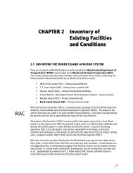
Ch 2 Precision Approach Feasibility - PVD
Ch 2 Precision Approach Feasibility - PVD
Ch 2 Precision Approach Feasibility - PVD

Create successful ePaper yourself
Turn your PDF publications into a flip-book with our unique Google optimized e-Paper software.
North Central State Airport<br />
<strong>Ch</strong>apter 2 – <strong>Precision</strong> <strong>Approach</strong> <strong>Feasibility</strong><br />
Airport Master Plan<br />
FINAL<br />
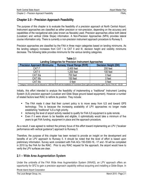
<strong>Ch</strong>apter 2.0 – <strong>Precision</strong> <strong>Approach</strong> <strong>Feasibility</strong><br />
The purpose of this chapter is to evaluate the feasibility of a precision approach at North Central Airport.<br />
Instrument approaches are classified as either precision or non-precision, depending on the accuracy and<br />
capabilities of the navigational aids (also known as Navaids) used. <strong>Precision</strong> approaches utilize both lateral<br />
(Localizer) and vertical (Glide Slope) information. A Non-<strong>Precision</strong> <strong>Approach</strong>es (NPA) provides lateral<br />
course information only. There is currently a non-precision instrument approach procedure to Runway 5.<br />
<strong>Precision</strong> approaches are classified by the FAA in three major categories based on landing minimums. As<br />
the landing category increases from CAT I to CAT II and III, decision height and visibility minimums<br />
decrease. The following table provides minimums for the various landing categories.<br />
Table 2.1<br />
Landing Categories for <strong>Precision</strong> Instrument <strong>Approach</strong>es<br />
<strong>Precision</strong> <strong>Approach</strong> Minimums Runway Visual Range (RVR) Decision Height (DH)<br />
CAT I* 2,400 feet 200 feet<br />
CAT II 1,200 feet 100 feet<br />
CAT IIIa 700 feet 0 feet<br />
CAT IIIb 150 feet 0 feet<br />
CAT IIIc 0 feet 0 feet<br />
*Category I minimums can be reduced to 1,800 feet RVR with the installation of Touchdown Zone Lights and Centerline Lights. Source: FAA AC- 120-29<br />
Initially, this effort intended to analyze the feasibility of implementing a “traditional” Instrument Landing<br />
System (ILS) precision approach (Localizer and Glide Slope ground based equipment). However a number<br />
of related factors lead RIAC to rethink its position. They include:<br />
• The FAA made it clear that their current policy is to move away from ILS and toward GPS<br />
technology. This is because the increasing availability of LPV approaches no longer made<br />
establishing “traditional” ILS a high priority.<br />
• Achieving the level of airport activity needed to qualify for FAA ILS equipment is quite remote.<br />
• Even if it were shown to be feasible and eligible, it optimistically would take a minimum of five<br />
years to get FAA funding, equipment in place and the approach procedure.<br />
As a result, it was agreed to redirect the primary focus of this effort toward implementing an LPV (“localizer<br />
performance with vertical guidance”) approach to Runway 5.<br />
Therefore, the purpose of this chapter has been revised to provide an insight on the development and<br />
benefits of an LPV approach to Runway 5. It should be noted that the level of effort is based upon<br />
preliminary information. Survey work consistent with FAA ACs 150-5300-16, -17 and -18 will be completed<br />
in 2010 by the FAA for the RIAC. Prior to any RIAC request for the approach, the airport would have to<br />
verify the LPV surfaces are clear.<br />
2.1 – Wide Area Augmentation System<br />
Under the umbrella of the FAA Wide Area Augmentation System (WAAS), an LPV approach offers an<br />
opportunity for SFZ to gain a precision approach capability without acquiring and installing a Glide-Slope. In<br />
Rhode Island Airport Corporation<br />
The Louis Berger Group, Inc. March 2010 - Page 2-1
North Central State Airport<br />
<strong>Ch</strong>apter 2 – <strong>Precision</strong> <strong>Approach</strong> <strong>Feasibility</strong><br />
Airport Master Plan<br />
FINAL<br />
fact, the LPV approach will require no ground based equipment at the airport other than the existing<br />
Localizer antennae.<br />
WAAS is a navigation service using a combination of Global Positioning System (GPS) satellites and the<br />
WAAS geostationary satellites to improve the navigational service provided by GPS. The system is owned<br />
and operated by the Federal Aviation Administration (FAA). WAAS is known to improve the navigational<br />
system accuracy for en route, terminal, and approach operations over all the continental United States.<br />
This new navigational technology supports vertically-guided instrument approaches to all qualifying<br />
runways in the U.S. Vertically-guided approaches reduce pilot workload and provide safety benefits<br />
compared to non-precision approaches. As mentioned, vertically-guided approach procedures (called LPV)<br />
can provide ILS equivalent approach minimums as low as 200 feet at qualifying airports. Actual minimums<br />
will be based upon SFZ’s current infrastructure, as well as an evaluation of any existing obstructions. The<br />
current lowest minimums to Runway 5 are 400 foot ceiling and ¾ mile visibility, as illustrated in Figure 2.1<br />
on the next page.<br />
2.1.1 Advantages of an LPV <strong>Approach</strong><br />
There are many advantages of a WAAS-enabled LPV approach. They are:<br />
• LPV procedures have no requirement for ground-based transmitters;<br />
• As a result, the often difficult task of siting ground based navigation equipment is eliminated, as<br />
well as providing and maintaining critical areas around the facility, or providing access for<br />
maintenance vehicles;<br />
• From a pilot’s viewpoint, an LPV approach looks and flies like an ILS, but the WAAS approach is<br />
more stable than that of an ILS; and,<br />
• WAAS equipped users can fly area navigation (RNAV) and basic required navigation performance<br />
(RNP) procedures, as well as LPV procedures, and the avionics costs are relatively inexpensive<br />
considering the total navigation solution provided.<br />
• Provides the opportunity to reduce the existing weather minimums, allowing better access to the<br />
airport during inclement weather conditions.<br />
Rhode Island Airport Corporation<br />
The Louis Berger Group, Inc. March 2010 - Page 2-2
North Central State Airport<br />
<strong>Ch</strong>apter 2 – <strong>Precision</strong> <strong>Approach</strong> <strong>Feasibility</strong><br />
Airport Master Plan<br />
FINAL<br />
Figure 2.1<br />
GPS <strong>Approach</strong> to SFZ Runway 5<br />
Rhode Island Airport Corporation<br />
The Louis Berger Group, Inc. March 2010 - Page 2-3
North Central State Airport<br />
<strong>Ch</strong>apter 2 – <strong>Precision</strong> <strong>Approach</strong> <strong>Feasibility</strong><br />
Airport Master Plan<br />
FINAL<br />
Figure 2.2 depicts a typical LPV approach procedure plate that the pilot refers to while flying the aircraft.<br />
The title denotes the approach as an RNAV procedure. Notice that each RNAV procedure typically includes<br />
three approach types; LPV, LNAV/VNAV, and LNAV. This enables as many GPS-equipped aircraft to use<br />
the procedure as possible and provides operational flexibility if WAAS becomes unavailable.<br />
Figure 2.2<br />
Sample LPV <strong>Approach</strong> Plate<br />
Rhode Island Airport Corporation<br />
The Louis Berger Group, Inc. March 2010 - Page 2-4
North Central State Airport<br />
<strong>Ch</strong>apter 2 – <strong>Precision</strong> <strong>Approach</strong> <strong>Feasibility</strong><br />
Airport Master Plan<br />
FINAL<br />
It is important to note that flying a WAAS LPV approach requires an aircraft with WAAS-LPV avionics. If for<br />
some reason the WAAS service becomes unavailable, all GPS or WAAS equipped aircraft can revert to the<br />
LNAV decision altitude and land safely using GPS-only, which is available nearly 100% of the time.<br />
2.2 – Preparing for an LPV <strong>Approach</strong> at SFZ<br />
The WAAS navigation service is fully operational and ready to provide the capability. Even though<br />
navigational equipment is not required there are still some airport infrastructure requirements to get a LPV<br />
approach. This section will provide preliminary information (i.e., weather, design standards, and obstruction<br />
surfaces) to assist RIAC in determining if it is feasible and practical to accommodate this type of approach<br />
procedure.<br />
2.2.1 Weather Analysis<br />
Weather analysis is an essential part in determining if it is realistic to provide reduced minimums at SFZ<br />
(i.e., better than the current 400 foot and ¾ mile). Consequently, a review of both visibility and ceiling height<br />
was conducted for the period 1997 through mid 2008. Table 2.2 summarizes the review and provides the<br />
percentage of the total measurements, taken for the period, that the airport is operating at various<br />
Instrument Meteorological Conditions (IMC).<br />
Table 2.2<br />
SFZ Weather Review<br />
(Based upon 177,447 Total Measurements)<br />
Visibility # of Measurements Percentage<br />
> 1 174,361 98.26%<br />
< 1 but ≥ ¾ 718 0.40%<br />
< ¾ but ≥ ½ 981 0.55%<br />
< ½ 1,387 0.78%<br />
Ceiling* # of Measurements Percentage<br />
> 400’ 160,883 90.66%<br />
400’ 2,742 1.55%<br />
300’ 3,451 1.94%<br />
200’ 4,554 2.57%<br />
100’ 5,817 3.28%<br />
400’ to 200’ 10,747 6.06%<br />
As shown, SFZ is operating at below the current visibility minimums (i.e., less than ¾) 1.33% of the total<br />
measurements taken for the period 1997-2008, and only .55% at the LPV operating threshold (greater than<br />
or equal to ½ mile). Furthermore, SFZ is operating below the current ceiling minimum (i.e., 400’) 6.06% for<br />
the same period.<br />
Quantitatively speaking, the first impression is there appears to be little benefit in providing reduced<br />
minimums. However, with the FAA’s added focus on WAAS (LPV) approaches across the U.S., SFZ may<br />
realize an added operational benefit in implementing an LPV to include added safety benefits and making<br />
the airport more accessible when it is needed under these climatological conditions. Qualitatively speaking,<br />
the weather conditions shown are a small portion of the overall time at the airport, but it can’t be stressed<br />
Rhode Island Airport Corporation<br />
The Louis Berger Group, Inc. March 2010 - Page 2-5
North Central State Airport<br />
<strong>Ch</strong>apter 2 – <strong>Precision</strong> <strong>Approach</strong> <strong>Feasibility</strong><br />
Airport Master Plan<br />
FINAL<br />
enough that improving the approach capabilities with lower minimums also enhances the level of safety<br />
when the pilot needs it most. As an added measure of safety, many pilots will fly an instrument approach<br />
during visual, good weather conditions. RIAC receives frequent inquiries and requests by pilots for reduced<br />
minimums, which further enhances the justification for pursuing an LPV at SFZ. It’s a “catch 22” situation.<br />
FAA is prepared to do the Survey, but not address the clearing requirements. The clearing will be the<br />
responsibility of RIAC and it is eligible for AIP reimbursement.<br />
2.2.2 Design Standards<br />
Although site requirements typically required for an ILS are unnecessary with an LPV approach,<br />
compliance with the design standards of Advisory Circular 150/5300-13 “Airport Design” still is required.<br />
Since the LPV approach may improve the existing capability, the airport infrastructure may require<br />
upgrading to accommodate the potential for increased activity by larger more complex aircraft. For this<br />
reason, a “table-top” evaluation was performed to determine if further actions, such as land acquisition,<br />
obstacle clearing, and upgrading airfield geometry and runway markings are required to achieve the full<br />
benefit of the LPV procedure. Once the scope of the infrastructure needs and costs are understood,<br />
informed decisions on the feasibility of implementing an LPV approach, along with options for funding can<br />
be realized.<br />
A review of the primary design standards was conducted under the premise that if and when SFZ<br />
implements an LPV approach, the increased usage of larger or complex aircraft may cause the airport to<br />
change from the current ARC B-II design standard to the expanded ARC C-II design requirements. Table<br />
2.3 shows the comparison between the existing airport conditions and the C-II design standard. To<br />
accommodate the difference would require capital improvements to bring the airfield up to the C-II<br />
standard.<br />
Table 2.3<br />
SFZ Design Standards (Current vs. C-II)<br />
Design Standard Existing (ft) C-II (ft) Deficit (ft)<br />
Runway CL to Taxiway CL 350 400 (50)<br />
Runway CL to Aircraft Parking 420 500 (80)<br />
Runway Width 100 100 Meets Reqt.<br />
RSA Width 500 500 Meets Reqt.<br />
RSA Length – 5 End 300 1,000 (700)<br />
RSA Length – 23 End 300 1,000 (700)<br />
OFA Width 500 800 (300)<br />
OFA Length 300 1,000 (700)<br />
RPZ Runway 5<br />
IW- 1,000<br />
OW- 1,510<br />
L- 1,700<br />
IW- 1,000<br />
OW- 1,750<br />
L- 2,500<br />
IW- 0<br />
OW- (240)<br />
L- (800)<br />
There is no evidence in the forecast (<strong>Ch</strong>apter 3), suggesting that the airport activity level for the higher<br />
performance aircraft (C-II) would dramatically increase because of the LPV. Nonetheless, if the design<br />
aircraft of the airport were to change, requiring C-II design standards; the costly investment in airport<br />
infrastructure needs to be understood now. These investments include, but are not limited to:<br />
Rhode Island Airport Corporation<br />
The Louis Berger Group, Inc. March 2010 - Page 2-6
North Central State Airport<br />
<strong>Ch</strong>apter 2 – <strong>Precision</strong> <strong>Approach</strong> <strong>Feasibility</strong><br />
Airport Master Plan<br />
FINAL<br />
• Substantial filling and grading at each end of Runway 5-23 to achieve the required 1,000’ RSA or<br />
partial fill and installation EMAS to achieve compliance;<br />
• Shifting Runway 5-23 or relocating Albion Road to accommodate the increased OFA width;<br />
• Shifting the parallel taxiway 50’ to achieve C-II separation standards;<br />
• Adding aircraft parking apron area development to offset aircraft parking lost from shifting the<br />
parallel taxiway and subsequent encroachment of the OFA;<br />
• Acquiring land required for the increased RPZ at the Runway 5 end and increased RSA at the<br />
Runway 23 end; and,<br />
• The cost of environmental and engineering studies required to implement all the improvements.<br />
Figure 2.3 illustrates the increased RSA, OFA, and RPZ from B-II to C-II.<br />
Based upon the desired minimums (200 foot decision height and ¾ mile visibility), the LPV requirements for<br />
runway length, lighting, and all-weather markings, as well the need for a parallel taxiway will need to be in<br />
place at SFZ. As shown in Table 2.4, with the exception of all-weather marking, SFZ currently meets the<br />
LPV requirements.<br />
Table 2.4<br />
Infrastructure Required for LPV <strong>Approach</strong><br />
RWY 5/23 Meets Requirements<br />
Runway Length > 4,200’ 5,000’ <br />
High Intensity Runway Edge Lighting (HIRL) HIRL <br />
Parallel Taxiway Yes <br />
<strong>Precision</strong> <strong>Approach</strong> Runway Markings<br />
No<br />
The goal is to cost effectively provide an infrastructure allowing for the lowest minimums and greater<br />
access to the airport in all weather conditions.<br />
2.2.3 Obstacle Environment and Key Surfaces<br />
The guidance accuracy required for a LPV approach is similar to that of an ILS. As such, the certification<br />
criteria used to define the lateral and vertical safety boundaries within which the aircraft will approach the<br />
runway are those used for an ILS. The certification criteria used to define the lateral and vertical tolerances<br />
are more critical than those used for non-precision approaches.<br />
In turn, this means that many obstacles which fall within the much wider V-shaped area of a non-precision<br />
approach may require a higher Decision Height (DH) to provide clearance over them and will fall outside<br />
the narrower LPV approach path. Ultimately this allows aircraft pilots to use a lower DH and makes for a<br />
more reliable airport.<br />
Rhode Island Airport Corporation<br />
The Louis Berger Group, Inc. March 2010 - Page 2-7
North Central State Airport<br />
<strong>Ch</strong>apter 2 – <strong>Precision</strong> <strong>Approach</strong> <strong>Feasibility</strong><br />
Airport Master Plan<br />
FINAL<br />
Several factors determine the minimums for an instrument approach. Implementing a LPV approach is no<br />
different. The two driving factors are the obstacles in the environment surrounding the airport and the<br />
airport infrastructure. The Height Above Touchdown (HAT) of the approach is based solely on the obstacles<br />
(natural or manmade) and how close they come to penetrating the glide slope obstacle clearance surfaces.<br />
Often these are beyond the control of airport management to clear and will affect the HAT for the approach.<br />
The visibility requirement for the approach is partly dependent upon the airfield infrastructure.<br />
Achieving the lowest visibility requires an obstacle clear surface and, as discussed in Section 2.2.2, the<br />
appropriate airport infrastructure to support the approach. The current obstruction data for SFZ does not<br />
provide all the information needed to make a detailed assessment of the appropriate airport surfaces. To<br />
obtain the detailed information would be premature and expensive at this point in the decision process and<br />
there are other variables that need to be considered first. Absent that data a broad “table-top” exercise was<br />
completed using guidance contained within TERPS FAA Order 8260.3B. This exercise reviewed the LPV<br />
clearance requirements based upon three key surfaces, which are the Glidepath Qualification Surface<br />
(GQS), the Obstacle Clearance Surface (OCS), and the <strong>Precision</strong> Object Free Zone (POFZ). These<br />
surfaces are defined as follows:<br />
• Glidepath Qualification Surface: The GQS extends from the runway threshold along the runway<br />
centerline extended to the Decision Altitude (DA) point. It limits the height of obstructions between<br />
DA and runway threshold. When obstructions exceed the height of the GQS, an approach<br />
procedure with positive vertical guidance (e.g., LPV) is not authorized, and subsequent review of<br />
the OCS is not necessary.<br />
• Obstacle Clearance Surface: The OCS is composed of the "W," "X," and "Y" surfaces (the "W,"<br />
"X," and "Y" surfaces are designed to protect both sides of the final approach course when the<br />
reported weather is 800 feet or less and the visibility is two SM or less and the aircraft is on final<br />
within two NM of the runway threshold.<br />
• <strong>Precision</strong> Object Free Zone: The POFZ is an area designed to protect the area of short final<br />
during very low ceilings of less than 300 feet or visibilities less than ¾-statute mile (SM) or less<br />
than 4,000 feet runway visual range (RVR).<br />
Because the “table-top” exercise could not accurately identify specific obstructions, the effort was primarily<br />
focused on identifying the extent of the areas impacted, and based upon a review of the ground contours,<br />
the potential for obstructions based upon an aerial review. Figure 2.4 illustrates the GQS and Figure 2.5<br />
illustrates the OCS (internal W surface only) and the POFZ.<br />
Rhode Island Airport Corporation<br />
The Louis Berger Group, Inc. March 2010 - Page 2-8
North Central State Airport<br />
Working Paper #2: LPV - <strong>Precision</strong> <strong>Approach</strong> <strong>Feasibility</strong><br />
[Insert Figure 2.4 – Runway 5 Glidepath Qualification Surface]<br />
Rhode Island Airport Corporation<br />
The Louis Berger Group, Inc.
North Central State Airport<br />
Working Paper #2: LPV - <strong>Precision</strong> <strong>Approach</strong> <strong>Feasibility</strong><br />
[Insert Figure 2.5 – Runway 5 Obstacle Clearance Surface]<br />
Rhode Island Airport Corporation<br />
The Louis Berger Group, Inc.
North Central State Airport<br />
<strong>Ch</strong>apter 2 – <strong>Precision</strong> <strong>Approach</strong> <strong>Feasibility</strong><br />
Airport Master Plan<br />
FINAL<br />
As illustrated in Figure 2.4, the GQS appears to be clear of obstructions at a 28.7:1 slope up to the potential<br />
Decision Height (DH) of 200 feet. The terrain drops off from the Runway 5 threshold to the southeast. The<br />
POFZ appears to be clear of obstructions. However, as illustrated in Figure 2.5, the OCS-W surface, at a 0<br />
slope for 2,579 feet could potentially have obstructions. Initial review indicates that the potential tree<br />
obstructions may exist inside and outside the airport property boundary. As Figure 2.6 illustrates, areas<br />
within the OCS-W surface have been outlined that have not been cleared (specifically Areas B and C), to<br />
date, and may contain obstructions.<br />
The following assumption has been made in effort to estimate the total acreage that will require clearing:<br />
• Ten (10) to Forty (40) percent of the areas both on and off RIAC property that have not been<br />
cleared (i.e., Areas B and C) may require obstruction removal.<br />
Tables 2.5 and 2.6 show the estimated clearing requirement (in acres) within the OCS-W surface and<br />
associated cost for obstruction removal.<br />
Table 2.5<br />
10 Percent - SFZ OCS-W Surface Clearing Estimate (Acreage and Cost)<br />
OCS – W<br />
Surface 1<br />
Acres<br />
10% of<br />
Total<br />
Acreage<br />
Estimated<br />
Unit Cost 2<br />
Estimated<br />
Cost to<br />
Remove<br />
Add<br />
Easement<br />
Cost<br />
Total<br />
Estimated<br />
Cost<br />
Area A<br />
N/A – Area is Clear<br />
Area B 21.6 2.16 $8k/acre $17,280 $0 $17,280<br />
Area C 10.6 1.06 $8k/acre $8,480 $50,000 $58,480<br />
Area D<br />
N/A – Area is Clear<br />
40% Total Estimated Cost (Rounded): $76,000<br />
1 Refer to Figure 2.6<br />
2 Obstruction Removal. Unit was derived from SFZ Engineers Opinion of Construction Costs for the Vegetative<br />
Obstruction Removal and Obstruction Lighting project (Fall 2008)<br />
OCS – W<br />
Surface 1<br />
Table 2.6<br />
40 Percent - SFZ OCS-W Surface Clearing Estimate (Acreage and Cost)<br />
40% of<br />
Estimated Add<br />
Estimated<br />
Acres Total<br />
Unit Cost<br />
Acreage<br />
2 Cost to Easement<br />
Remove Cost<br />
Total<br />
Estimated<br />
Cost<br />
Area A<br />
N/A – Area is Clear<br />
Area B 21.6 8.64 $8k/acre $69,120 $0 $69,120<br />
Area C 10.6 4.24 $8k/acre $33,920 $75,000 $108,920<br />
Area D<br />
N/A – Area is Clear<br />
40% Total Estimated Cost (Rounded): $180,000<br />
1 Refer to Figure 2.6<br />
2 Obstruction Removal: Unit was derived from SFZ Engineers Opinion of Construction Costs for the Vegetative<br />
Obstruction Removal and Obstruction Lighting project (Fall 2008)<br />
A more detailed Aeronautical Survey, which is discussed in Section 2.3, is necessary to verify the<br />
estimations provided in Tables 2.5 and 2.6, and Figure 2.6 as well as allow a more detailed analysis of the<br />
OCS- X and Y peripheral surfaces. That survey is recommended as a component of the Phase I<br />
development recommendations.<br />
Rhode Island Airport Corporation<br />
The Louis Berger Group, Inc. March 2010 - Page 2-11
North Central State Airport<br />
<strong>Ch</strong>apter 2 – <strong>Precision</strong> <strong>Approach</strong> <strong>Feasibility</strong><br />
Airport Master Plan<br />
FINAL<br />
Figure 2.6 Here.<br />
Rhode Island Airport Corporation<br />
The Louis Berger Group, Inc. March 2010 - Page 2-12
North Central State Airport<br />
<strong>Ch</strong>apter 2 – <strong>Precision</strong> <strong>Approach</strong> <strong>Feasibility</strong><br />
Airport Master Plan<br />
FINAL<br />
2.3 – Recommendation and Next Steps<br />
As discussed in the previous section, a preliminary review of the clearance surfaces indicates that SFZ<br />
appears to be a viable candidate for an LPV approach to Runway 5. Furthermore, LPV requirements<br />
indicate that SFZ meets all but one requirement, that is, <strong>Precision</strong> <strong>Approach</strong>, all weather runway markings.<br />
An investment to upgrade runway markings is relatively small.<br />
If the airport were to experience a significant increase in C-II aircraft operations (> 500 operations/year),<br />
this would then require significant and costly infrastructure upgrades listed in Section 2.2.2. The forecasts<br />
provided in this report (<strong>Ch</strong>apter 3) indicate that such an increase in C-II operations is unlikely.<br />
Implementation of an LPV approach at SFZ is warranted due to the added benefit of the new and<br />
increasingly utilized technology. The gains for aircraft operators are significant considering the number of<br />
airports like SFZ that do not have an ILS. Most business oriented aircraft operations are conducted from<br />
non ILS airports and are restricted to use non precision approaches. As more complex aircraft are being<br />
equipped with WAAS capability, SFZ could experience an ‘opportunity gained’ by implementing the LPV<br />
approach and realizing the full potential of the airport. Use of the precision LPV approach at SFZ would<br />
enhance the use of the airport during poor weather conditions by achieving lower instrument approach<br />
minimums rather than diverting to an alternate airport. By its very nature this also improves the safety of the<br />
airspace system.<br />
Since the last obstruction study for SFZ was completed in 1996, an updated obstruction analysis is<br />
essential to determine the exact approach minimums the installation of an LPV would achieve. However,<br />
review of this obstruction data suggests that there would be at least some improvement.<br />
Before an LPV can be implemented, several steps must be performed which include the following:<br />
1. Perform an LPV Aeronautical Survey Update at the Runway 5 end (previous survey was conducted<br />
in 1996). Requests for new or revised Instrument <strong>Approach</strong> Procedures (IAP) require the submittal<br />
of current and accurate airport data meeting FAA requirements (see Attachment A for sample<br />
Scope-of-Work); Research indicates that the costs associated with implementing an LPV approach<br />
at SFZ range from $200,000 to $450,000 based on the following approximate costs:<br />
o Aeronautical Survey $150,000<br />
o Design, Easements and Obstruction Removal 200,000<br />
o EA for tree clearing/obstruction removal<br />
o Runway Markings 50,000<br />
o Contingency 50,000<br />
Approximate Cost: $450,000<br />
2. Analyze survey results to determine the LPV approach minimums; and,<br />
3. Submit an official request for development of the LPV procedure to the FAA.<br />
After the obstruction survey is analyzed and the LPV minimums are determined, there will be relatively no<br />
cost associated with publishing the LPV approach at SFZ. Once the request is submitted, it will be reviewed<br />
by the FAA. This review usually incorporates FAA airports, flight procedures, flight standards, and air traffic<br />
control to provide a single coordinated review of the request. Once approved by the FAA, the priority for<br />
publication is established and the procedure development scheduled.<br />
Rhode Island Airport Corporation<br />
The Louis Berger Group, Inc. March 2010 - Page 2-13