Chapter 6.0 â Airport Layout Plan - PVD
Chapter 6.0 â Airport Layout Plan - PVD
Chapter 6.0 â Airport Layout Plan - PVD

You also want an ePaper? Increase the reach of your titles
YUMPU automatically turns print PDFs into web optimized ePapers that Google loves.
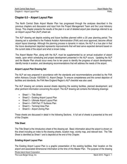
North Central State <strong>Airport</strong><strong>Chapter</strong> 6 – <strong>Airport</strong> <strong>Layout</strong> <strong>Plan</strong><strong>Airport</strong> Master <strong>Plan</strong>FINAL<strong>Chapter</strong> <strong>6.0</strong> – <strong>Airport</strong> <strong>Layout</strong> <strong>Plan</strong>The North Central State <strong>Airport</strong> Master <strong>Plan</strong> has progressed through the analyses described in theprevious chapters and discussion and input from the Project Management Team and the Local AdvisoryGroup. This chapter presents the results of the plan in a set of detailed airport plan drawings referred to asan <strong>Airport</strong> <strong>Layout</strong> <strong>Plan</strong> (ALP) sheet set.The ALP drawing set depicts existing and future facilities planned within a 20 year planning period. Thedrawing set is submitted to the Federal Aviation Administration (FAA) and once approved, become officialairport layout drawings. Although the planning process is dynamic in nature, the ALP is a true plan in thatthe future development depicted represents improvements that will best serve expected demand based onthe current state of the airport and what is known today.The <strong>Airport</strong> Master <strong>Plan</strong>, along with the ALP, must be supplemented by an annual evaluation of airportneeds, upon which scheduling and project development presented in the ALP occurs. Updating the ALPand the Master <strong>Plan</strong> should occur every five to ten years to identify the progress of airport development,identify trends in aviation, and developing recommendations that will address the needs of the airport.<strong>Airport</strong> <strong>Layout</strong> <strong>Plan</strong> Drawing SetThe ALP set was prepared in accordance with the standards and recommendations provided by the FAAwithin Advisory Circular 150/5300-13, <strong>Airport</strong> Design. To ensure completeness and the correct depiction offacilities and standards, the FAA New England Region’s ALP checklist was also used.The ALP drawing set contains several sheets depicting the existing facilities, planned development, andother pertinent information concerning the airport. The ALP drawing set contains the following drawings:• Sheet 1 – Title Sheet• Sheet 2 – Existing <strong>Airport</strong> <strong>Layout</strong> <strong>Plan</strong>• Sheet 3 – Ultimate <strong>Airport</strong> <strong>Layout</strong> <strong>Plan</strong>• Sheet 4 – FAR Part 77 Surfaces <strong>Plan</strong>• Sheet 5 – Terminal Area <strong>Plan</strong>• Sheet 6 – <strong>Airport</strong> Zoning <strong>Plan</strong>These sheets are discussed in detail in the following Sections. A full set of sheets is presented at the endof this <strong>Chapter</strong>.Title SheetThe Title Sheet is the introductory sheet of the drawing set. Basic information about the airport is shown onthis sheet including an index to the drawing sheets, location map, vicinity map, and relevant text. The TitleSheet is identified as Sheet 1 and is depicted at the end of this <strong>Chapter</strong>.Existing <strong>Airport</strong> <strong>Layout</strong> <strong>Plan</strong>The Existing <strong>Airport</strong> <strong>Layout</strong> <strong>Plan</strong> is a graphic presentation of the existing facilities, their location on theairport and associated dimensional information at the time of this Master <strong>Plan</strong>. The purpose of the drawingRhode Island <strong>Airport</strong> CorporationThe Louis Berger Group, Inc. March 2010 - Page 6 - 1
North Central State <strong>Airport</strong><strong>Chapter</strong> 6 – <strong>Airport</strong> <strong>Layout</strong> <strong>Plan</strong><strong>Airport</strong> Master <strong>Plan</strong>FINALis to show the existing layout and act as a reference for future development shown on the Ultimate <strong>Airport</strong><strong>Layout</strong> <strong>Plan</strong>. Information provided on this drawing includes data tables, airfield facilities, surroundingtransportation infrastructures, off airport buildings, and relevant topography. The Existing <strong>Airport</strong> Facilities<strong>Plan</strong> is identified as Sheet 2 and is located at the end of this <strong>Chapter</strong>.Ultimate <strong>Airport</strong> <strong>Layout</strong> <strong>Plan</strong>The Ultimate <strong>Airport</strong> <strong>Layout</strong> <strong>Plan</strong> depicts the proposed projects identified in the, Alternatives Analysischapter of the Master <strong>Plan</strong>. The projects shown are for the full 20-year planning period through 2029. Itshould be noted that implementation of these projects will be phased, based on facility priorities, as follows:Phase I: 2009 – 2014, Phase II: 2014 – 2019, and Phase III 2019 – 2029.Additional information shown on the ALP includes data blocks identifying existing and proposed facilities;VFR and IFR wind roses; existing buildings; revision blocks; and signature blocks for the FAA and RIAC.Topography, local road infrastructure, and surrounding buildings are also shown on this drawing. TheUltimate ALP is identified as Sheet 3 at the end of this <strong>Chapter</strong>.FAR Part 77 Surfaces <strong>Plan</strong>This drawing shows the full FAR Part 77 Imaginary Surfaces on a USGS Quadrangle map. This drawingincludes a plan view of all 14 CFR Part 77 surfaces. This plan assists surrounding jurisdictions indetermining if the construction of a proposed structure will penetrate any aeronautical surfaces. The FARPart 77 Surfaces <strong>Plan</strong> is identified as Sheet 4 at the end of this <strong>Chapter</strong>Terminal Area <strong>Plan</strong>The Terminal Area <strong>Plan</strong> shows the location and configuration of existing and proposed buildings and pavedareas in the terminal area of the airport, including hangars and parking lots. The contents of the TerminalArea <strong>Plan</strong> include a large scale plan view of the area; building data table; existing and proposed facilities;and a legend table. Provided as part of the Terminal <strong>Plan</strong> is a separate viewport that graphically depictsfuture development adjacent to Taxiway “A” on the Runway 33 end. The Terminal Area <strong>Plan</strong> is identified asSheet 5 at the end of this <strong>Chapter</strong>.<strong>Airport</strong> Land Use <strong>Plan</strong>The <strong>Airport</strong> Land Use <strong>Plan</strong>, identified as Sheet 6 at the end of this Section, shows existing land use withinthe airport’s property limits and the airport vicinity in general. This drawing can be used to assist RIAC witha plan for zoning, and provides guidance to local authorities for establishing zoning. The <strong>Airport</strong> Land Use<strong>Plan</strong> is the final sheet in the airport layout plan set and is identified as Sheet 6 provided herein.Rhode Island <strong>Airport</strong> CorporationThe Louis Berger Group, Inc. March 2010 - Page 6 - 2