XAR Digital Alternator Regulator - Xantrex
XAR Digital Alternator Regulator - Xantrex
XAR Digital Alternator Regulator - Xantrex

Create successful ePaper yourself
Turn your PDF publications into a flip-book with our unique Google optimized e-Paper software.
<strong>XAR</strong> <strong>Digital</strong> <strong>Alternator</strong> <strong>Regulator</strong><br />
Installation and Operation Manual<br />
I. INTRODUCTION<br />
Thank you for choosing your <strong>Xantrex</strong> <strong>Alternator</strong> <strong>Regulator</strong> (<strong>XAR</strong>) multi-stage regulator.<br />
This regulator has been designed to maximize the charging efficiency of your DC<br />
system, and can be used with many P-type, externally regulated alternators.<br />
The <strong>XAR</strong> is designed to provide superior charge control for most common battery<br />
types. Both models are pre-programmed at the factory for universal, “out-ofthe-box”<br />
operation with most batteries. Built-in selectable programs for<br />
Deep-Cycle Lead Acid, AGM, Gel and Optima battery types are also<br />
available on both regulator models. In addition, the <strong>XAR</strong> provides an<br />
Amp Manager for precise alternator output control. Manual equalization,<br />
required for some battery types, is available. Data ports, for use<br />
with future optional remote displays, are included on both regulators.<br />
The <strong>XAR</strong> can monitor and compensate for alternator over-temperature conditions<br />
when combined with optional alternator temperature sensor (<strong>XAR</strong>-TS-A). The<br />
<strong>XAR</strong> also has the ability to monitor and compensate for under- or over-temperature<br />
conditions at one battery, when equipped with optional battery temperature<br />
sensor (<strong>XAR</strong>-TS-B). Maximum temperature compensated voltage is 14.8 volts.<br />
II. INSTALLATION<br />
1. Mount the regulator in a dry, well-ventilated place. Avoid installation in areas<br />
of excess heat and/or vibration. Avoid locations where regulator or<br />
wiring connections could be exposed to water or coolant.<br />
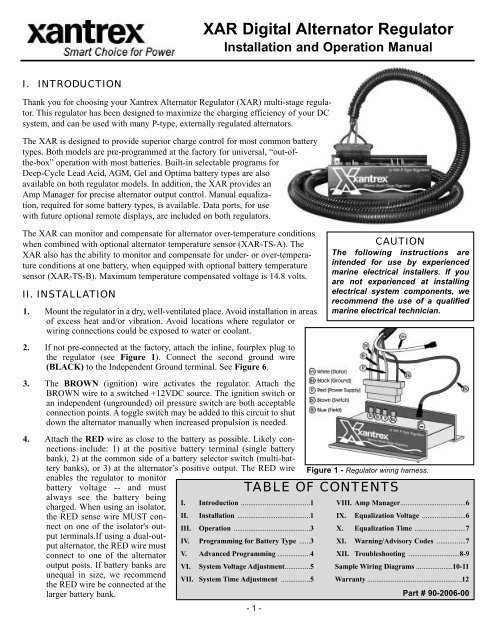
2. If not pre-connected at the factory, attach the inline, fourplex plug to<br />
the regulator (see Figure 1). Connect the second ground wire<br />
(BLACK) to the Independent Ground terminal. See Figure 6.<br />
3. The BROWN (ignition) wire activates the regulator. Attach the<br />
BROWN wire to a switched +12VDC source. The ignition switch or<br />
an independent (ungrounded) oil pressure switch are both acceptable<br />
connection points. A toggle switch may be added to this circuit to shut<br />
down the alternator manually when increased propulsion is needed.<br />
CAUTION<br />
The following instructions are<br />
intended for use by experienced<br />
marine electrical installers. If you<br />
are not experienced at installing<br />
electrical system components, we<br />
recommend the use of a qualified<br />
marine electrical technician.<br />
4. Attach the RED wire as close to the battery as possible. Likely connections<br />
include: 1) at the positive battery terminal (single battery<br />
bank), 2) at the common side of a battery selector switch (multi-battery<br />
banks), or 3) at the alternator’s positive output. The RED wire Figure 1 - <strong>Regulator</strong> wiring harness.<br />
enables the regulator to monitor<br />
battery voltage -- and must<br />
TABLE OF CONTENTS<br />
always see the battery being<br />
I. Introduction ......................................1 VIII. Amp Manager....................................6<br />
charged. When using an isolator,<br />
the RED sense wire MUST connect<br />
on one of the isolator's out-<br />
III. Operation ..........................................3 X. Equalization Time ............................7<br />
II. Installation ........................................1 IX. Equalization Voltage ........................6<br />
put terminals.If using a dual-output<br />
alternator, the RED wire must<br />
IV. Programming for Battery Type ......3 XI. Warning/Advisory Codes ................7<br />
connect to one of the alternator V. Advanced Programming ..................4 XII. Troubleshooting ............................8-9<br />
output posts. If battery banks are VI. System Voltage Adjustment..............5 Sample Wiring Diagrams ....................10-11<br />
unequal in size, we recommend<br />
VII. System Time Adjustment ................5 Warranty ....................................................12<br />
the RED wire be connected at the<br />
larger battery bank.<br />
Part # 90-2006-00<br />
- 1 -
II. INSTALLATION (Continued)<br />
4. (Continued). If the smaller battery shows signs of overcharging, the RED wire can<br />
be moved to the smaller battery terminal on the isolator. The same is true in the<br />
case of a dual-output alternator. The RED wire carries up to 6 amps and should be<br />
protected with the 10A fuse included with the regulator. Fusing should be as close<br />
to the power source as possible. If lengthening of the RED wire is needed, upgrade<br />
wire to 12-gauge.<br />
5. Connect the two BLACK ground wires at the preferred ground at the rear of the<br />
alternator (see Figure 2 for typical alternator ground connection).<br />
6. Connect duplex plug with BLUE and WHITE wires to the alternator. If your alternator<br />
doesn’t provide for a plug connection, see alternator manual for installation<br />
instructions.<br />
7. If your application utilizes an electric tachometer, connect one end of the WHITE<br />
stator wire to the alternator and the other end to the regulator. A Tach Out terminal<br />
is provided for connection to your tachometer. If a new alternator is being installed,<br />
ensure that your tachometer is adjusted to meet your alternator's pole<br />
setting.<br />
8. Attach optional <strong>Alternator</strong> Temp Sensor to the <strong>Alternator</strong> Temp<br />
Sensor terminals shown in Figure 6. Observe polarity. Attach sensor<br />
to alternator case as shown in Figure 3. Installing a toggle switch<br />
between the positive and negative terminals of the <strong>Alternator</strong><br />
Temperature Sensor circuit allows you to reduce alternator output and<br />
horsepower load by 50% (Small Engine Mode).<br />
9. Attach optional Battery Temp Sensor wires as shown in Figure 6.<br />
Observe polarity. Attach Battery Temp Sensor lug to negative battery<br />
terminal as shown in Figure 4. If used in a multi-battery bank, place<br />
as close to the middle of the bank as possible.<br />
10. The Alarm Output (Dash Lamp) terminal provides a circuit for dash<br />
mounted visual or audible system warnings. Terminal output is 250<br />
Mil-Amps (0.25A) negative when activated by low voltage (12.8V),<br />
high voltage (1V over bulk),<br />
high alternator temp (225F),<br />
or high battery temp (125F).<br />
The Aux. Out terminal operates<br />
the same as the alarm<br />
output and activates at alt. full<br />
capacity, small engine mode,<br />
and during equalization.<br />
NOTE<br />
Connection of the WHITE stator<br />
wire to the regulator is only recommended<br />
when an electric tach is<br />
used. Do not connect the WHITE<br />
wire to the regulator if your<br />
tachometer is being driven<br />
mechanically. Doing so may result<br />
in higher-than-recommended surface<br />
voltages at the batteries, as the<br />
regulator attempts to compensate<br />
for full battery capacity. If voltage<br />
climbs above normal levels, add a<br />
load (cabin lights, fan, etc.) to<br />
return the system to normal levels.<br />
Figure 3 - Optional<br />
<strong>Alternator</strong> Temperature<br />
Sensor. Attach to midcase<br />
mounting bolt.<br />
Figure 2 - Ground attachment. Both<br />
grounds connect together at preferred<br />
ground terminal.<br />
Figure 4 - Optional<br />
temp sensor on battery.<br />
Connect to negative<br />
terminal.<br />
Primary Program Settings PRG-1 PRG-2 PRG-3 PRG-4 PRG-5<br />
Universal Deep Cycle Gel Absorbed Optima<br />
Factory Flooded Cell Glass Spiral<br />
Mode Program Lead Acid Mat (AGM) Wound<br />
Start Delay (Seconds) 45 45 45 45 45<br />
Ramp Up (Seconds) 60 60 60 60 60<br />
Bulk Voltage (Max) 14.1 14.6 14.1 14.4 14.6<br />
Bulk Time (Minimum) 30 min. 30 min. 30 min. 30 min. 30 min.<br />
Absorption Voltage 13.9 14.4 13.9 14.2 14.4<br />
Absorption Time (Minimum) 0.2 hr. 0.2 hr. 0.2-2.0 hr. 0.2-2.0 hr. 0.2-2.0 hr.<br />
Float Voltage 13.4 13.4 13.7 13.4 13.4<br />
Float Time (Maximum) 6 hr. 6 hr. 6 hr. 6 hr. 6 hr..<br />
High Voltage Alarm 15.2 15.6 15.1 15.4 15.6<br />
Low Voltage Alarm 12.8 12.8 12.8 12.8 12.8<br />
Max Battery Temperature 125F/52C 125F/52C 125F/52C 125F/52C 125F/52C<br />
Max <strong>Alternator</strong> Temperature 225F/107C 225F/107C 225F/107C 225F/107C 225F/107C<br />
Equalization Yes Yes No Consult Mfg. Consult Mfg.<br />
Figure 5 - Preset program values. Voltages may vary by +/- 3% from values shown.<br />
Figure 6 - <strong>Regulator</strong> terminal layout and function description. Locations may vary by regulator<br />
version. See label on side of regulator.<br />
- 2 -
III. OPERATION<br />
Once the regulator is properly installed and connected to the rest of the charging system, it is ready to use. During operation, a<br />
bank of eight (8) color-coded LED lights will<br />
illuminate to provide programming, mode,<br />
diagnostic and advisory information. At startup,<br />
all eight LED lights will illuminate for<br />
approximately three seconds (Figure 7).<br />
Arrows indicate illuminated LEDs.<br />
The initial display will be followed by a display which indicates battery program type (Figure 8). Out of the box, this will indicate<br />
the Universal Factory Program mode<br />
Reed Switch<br />
Figure 8 - Indicates<br />
(indicated by a single green LED furthest<br />
Activation Test<br />
preset program.<br />
from amber LED). Two green LEDs indicate<br />
Flooded Deep Cycle. Three green factory program shown.) G G G G A R A A<br />
(Program #1 - Universal<br />
LEDs indicate Gel. Four green LEDs indicate<br />
Absorbed Glass Mat (AGM) battery. A single green LED closest to the illuminated amber LED indicates Optima battery<br />
setting.<br />
The display will then cycle through the various charging stages (Figure 9). Single green LED furthest from the amber LED<br />
indicates 45-second start delay. Two illuminated<br />
green LEDs indicate soft ramp and bulk Figure 9 - Indicates<br />
charging stage. Three illuminated green LEDs charging stage. (Start<br />
indicate absorption stage. Four illuminated delay shown.)<br />
G G G G A R A A<br />
green LEDs indicate float stage.<br />
During normal operation, the regulator will delay alternator start-up for 45 seconds to allow belts to seat and engine lubrication<br />
to occur. After the initial start delay, the regulator will ramp to charging voltage over a one-minute period. Once bulk charging<br />
voltage is reached, the regulator will remain in the bulk stage for a minimum of 36 minutes. At the end of the 36-minute period,<br />
the regulator will compare actual battery voltage with target voltage (based on battery type) and determine whether to<br />
advance to absorption stage, or add additional 6-minute increments at bulk voltage until target voltage is reached.<br />
Once in absorption stage, the regulator will remain at absorption voltage for a minimum of 36 minutes. Additional 6-minute<br />
increments will be added thereafter until target voltage is attained. <strong>Regulator</strong> will remain in float stage for a minimum of two<br />
hours, after which, it will cycle back to absorption stage for a minimum of 36-minutes. This cycle will continue throughout<br />
engine operation. Note: The regulator will automatically return to the beginning of the charging program if the engine is<br />
shut down and re-started.<br />
IV. PROGRAMMING FOR BATTERY TYPE<br />
The <strong>XAR</strong> is factory preset for universal, “plug-and-play” operation with most battery<br />
types. In addition to the default factory program, both models feature selectable programs<br />
for Deep-Cycle flooded, AGM, Gel and Optima battery types. (A list of detailed voltage<br />
and time values for the various presets is available on the previous page. See Figure 5.) A<br />
magnetic reed switch, located beside the first green LED enables user adjustment. The<br />
switch works in two specific actions, as described in the box at right.<br />
To select a program for your battery type:<br />
Figure 7 -<br />
Indicates system<br />
start-up.<br />
1. Turn ignition key to its ON position. Allow the regulator to<br />
cycle through the 45-second start delay and into the rampup/bulk<br />
stage (indicated by the two illuminated green<br />
LEDs).<br />
2. Using the supplied magnetic screwdriver (as shown in<br />
Figure 11), ACTIVATE-HOLD as discussed in the<br />
instructions at right. The #5 amber light and #6 flashing<br />
red light will illuminate to indicate switch activation<br />
(Figure 10).<br />
Switch Activated<br />
Flashing<br />
G G G G A R A A<br />
Figure 10 - Indicates magnetic switch is activated.<br />
G G G G A R A A<br />
Figure 11 - Magnetic<br />
reed switch / LED location.<br />
- 3 -<br />
‘ACTIVATE-RELEASE’ Refers<br />
to the activation and immediate<br />
deactivation of the switch by<br />
lowering the supplied magnetic<br />
screwdriver on the upper corner<br />
of the switch, and immediately<br />
deactivating the switch by<br />
removing the magnet from the<br />
switch.<br />
‘ACTIVATE-HOLD-RELEASE’<br />
Used primarily during user programming,<br />
this action requires<br />
holding the magnet to the switch<br />
until desired values are shown<br />
on the display. Once the desired<br />
setting is reached, the magnet is<br />
removed to deactivate the<br />
switch.<br />
NOTE: The cycle speed for the display<br />
is five seconds. The regulator cycles at<br />
this rate to ensure adequate time to<br />
read LED codes and make adjustments.
3. The red LED will stop flashing and the #7 amber light will illuminate shortly thereafter to indicate the battery preset program<br />
mode is engaged (Figure 12).<br />
Figure 12 - Indicates Switch Activated<br />
4. As you continue to hold, the green preset program mode.<br />
lights on the left half of the LED display<br />
will be illuminated one-by-one to<br />
G G G G A R A A<br />
indicate battery type. The first green LED on the left will indicate Program 1 (Universal Factory Program). As you continue<br />
to hold the magnet to the switch, the display will cycle to the first two green LEDs (indicating Program 2 - Deep<br />
Cycle), three green LEDs (indicating Program 3 - Gel), four green LEDs (indicating Program 4 - AGM), or a single<br />
green LED closest to amber LED (indicating Program 5 - Optima).<br />
5. When the desired preset program is indicated, release the reed switch by removing your magnetic tool from the switch.<br />
Once a preset has been selected and the switch has been deactivated, the #5 amber light will go out, indicating that the<br />
switch has been deactivated. The green LED lights will remain for several second before going out (Figure 13).<br />
6. Once the green lights have gone out,<br />
you may change your selection by reapplying<br />
the magnet to the switch.<br />
The program choices will scroll in<br />
reverse order. Note: Keep in mind<br />
that the display will stop scrolling once it reaches selection one or five (depending on if you are ascending or<br />
descending in the program mode). It will be necessary to release the switch, wait for the green lights to go out, and reapply<br />
the magnet to the switch to scroll in the opposite direction.<br />
7. If the switch is not re-activated for several seconds,<br />
the #7 amber LED will flash (Figure 14) to indicated<br />
that the program changes have been saved and<br />
the display will return to the “basic” mode as<br />
described in Section III.<br />
V. ADVANCED PROGRAMMING<br />
Advanced Programming modifies preset programming to suit specific charging needs. Advanced programming includes voltage<br />
adjustment, time adjustment, and equalization (time and voltage) adjustment. (Equalization is only suggested for batteries<br />
noted as “equalization friendly” in Figure 5 on Page 2). Consult your battery manufacturer for equalization time and voltage<br />
recommendations. Equalization must be initiated through the advanced programming mode. It is NOT a standard mode of<br />
operation. Both EQ time and voltage must be set for equalization to occur. Equalization will occur immediately after the program<br />
has been saved into memory. Once equalization is complete, the regulator will cycle to float mode. The <strong>XAR</strong> also features<br />
an adjustable Amp Manager, which enables you to control the percentage of total alternator output. This feature can be<br />
helpful in eliminating belt slippage which may occur if your drive belt is too small for the alternator load. NOTE: Advanced<br />
Programming modifications can be removed from the regulator's memory by reselecting the original program for your<br />
battery type. NOTE #2: The Advanced Programming Mode will cycle three times before saving new settings to memory.<br />
To enter to Advanced programming<br />
mode:<br />
Switch Activated<br />
Flashing<br />
1. ACTIVATE-HOLD the magnetic reed<br />
switch. LED #5 will illuminate and<br />
LED #6 will flash several times<br />
(Figure 15).<br />
2. Continue holding switch. LED #6 stops<br />
flashing, then LED #7 illuminates. This<br />
indicates the regulator has entered the<br />
advanced program mode (Figure 16).<br />
3. RELEASE the switch. The #5 amber<br />
LED will go out. The #7 amber LED<br />
will remain for several seconds and<br />
will be replaced by the #8 amber LED,<br />
indicating that the regulator is in the<br />
System Voltage Adjustment mode (Figure 17).<br />
Figure 13 - Indicates<br />
program has been<br />
selected and switch has<br />
been released.<br />
Figure 15 - Indicates<br />
entry to Advanced<br />
Programming mode.<br />
Figure 16 - Indicates<br />
activation of Advanced<br />
Program mode.<br />
Figure 17 - Indicates<br />
entry into the Advanced<br />
System Voltage<br />
Adjustment mode.<br />
G G G G A R A A<br />
Flashing<br />
G G G G A R A A<br />
Figure 14 - Indicates program has been save to memory. <strong>Regulator</strong><br />
will reset and return to its basic operational display.<br />
G G G G A R A A<br />
Switch Activated<br />
G G G G A R A A<br />
G G G G A R A A<br />
The display will scroll three times through all of the Advanced Programming modes (System Voltage, System Time, Amp<br />
Manager, EQ Voltage, EQ Time). You may wait until the desired adjustment mode is reached before activating the<br />
switch.<br />
- 4 -
VI.<br />
SYSTEM VOLTAGE ADJUSTMENT<br />
The Voltage Adjustment mode allows you to increase or decrease the voltage values built into the preset programs based on battery<br />
type. Note: Changes in charging voltages affect ALL stages of the charging program. Keep in mind that the display<br />
has been programmed to provide approximately five seconds between value changes. This time period is provided to ensure<br />
correct adjustments. To adjust system voltage values:<br />
1. When the LED indicates entry into the system voltage mode, as<br />
shown in Figure 17, ACTIVATE-HOLD the switch with your<br />
magnetic screwdriver (Figure 18). The display will begin to<br />
cycle up through the values shown in Figure 19. NOTE: To<br />
reverse scrolling direction, release the switch, wait until the<br />
Switch Activated<br />
G G G G A R A A<br />
Figure 18 - Indicates activation of System Voltage<br />
Adjustment. Green LEDs indicate as shown in Figure 19.<br />
green lights turn off, and re-activate and hold the switch to<br />
cycle the opposite direction.<br />
2. When the display indicates your desired voltage adjustment,<br />
RELEASE the switch.<br />
3. After several seconds, the green indicator lights will turn off.<br />
4. If no changes are made to your selection, the #8 amber light<br />
will flash once, indicating that your selection has been<br />
accepted.The display will advance to the System Time<br />
Adjustment mode.<br />
VII. SYSTEM TIME ADJUSTMENT<br />
The System Time Adjustment enables you to modify charging time<br />
values to meet your battery bank’s specific charging needs. Keep<br />
in mind, changes in charging times affect ALL charging stages. To<br />
modify charging time values:<br />
1. When the LED display indicates entry into the system time<br />
adjustment mode, as shown in Figure 20, ACTIVATE-<br />
HOLD the switch with your magnet. The display will<br />
cycle up through the values shown in Figure 22. NOTE:<br />
To reverse scrolling direction, release the switch, wait<br />
until the green lights turn off, and re-activate and hold<br />
the switch to cycle the opposite direction. Keep in mind<br />
that the display has been programmed to provide approximately<br />
five seconds between value changes.<br />
2. When the display indicates your desired system time<br />
adjustment, RELEASE the switch.<br />
3. After several seconds, the green LEDs will turn off.<br />
4. If no changes are made to your selection, the #7 and #8<br />
(amber) lights will flash once, indicating that your selection<br />
has been accepted. The display will advance to the<br />
Amp Manager programming mode as illustrated in<br />
Figure 23.<br />
Figure 19 - Indicates entry into the Advanced System<br />
Voltage adjustment mode. Adjustment<br />
begins at System Voltage setting.<br />
G G G G A R A A<br />
Figure 20 - Indicates entry into Advanced System Time<br />
Adjustment.<br />
Switch Activated<br />
G G G G A R A A<br />
Figure 21 - Indicates Advanced System Time Adjustment.<br />
Green LEDs indicate as shown in Figure 22.<br />
Figure 22 - Illustrates system time values as indicated<br />
by LED readout.<br />
- 5 -<br />
G G G G A R A A<br />
Figure 23 - Indicates entry into Amp Manager Adjustment.
VIII. AMP MANAGER<br />
The Amp Manager function enables you to reduce the alternator’s output by controlling the voltage at the field wire. This feature<br />
can be used as a method to minimize alternator overheating in warmer climates, or to minimize difficulties with belt slippage.<br />
To adjust Amp Manager values:<br />
1. When the LED display indicates entry into the Amp Manager<br />
mode, as shown in Figure 23 on the previous page, ACTI-<br />
VATE-HOLD the switch with your magnetic tool. The display<br />
will indicate initial entry into Amp Manager program mode as<br />
illustrated in Figure 24, after which, the display will indicate<br />
Switch Activated<br />
G G G G A R A A<br />
Figure 24 - Indicates activation of Amp Manager Adjustment.<br />
Field output reduction percentages are shown in Figure 25 at right.<br />
100% output. Release and re-activate after the green light goes<br />
out to scroll downward through the program selections.<br />
Reversing the process will scroll upward.<br />
2. When the display indicates your desired Amp Manager value as<br />
indicated in Figure 25, RELEASE the switch.<br />
3. After several seconds, the green indicator lights will turn<br />
off.<br />
4. If no changes are made to your selection, the #6 red and #7<br />
amber lights will flash once, indicating that your selection<br />
has been accepted. The display will advance to the<br />
Equalization Voltage Adjustment mode as indicated in<br />
Figure 26.<br />
IX. EQUALIZATION VOLTAGE<br />
The onset of sulfation can be lessened in some battery types by<br />
periodic introduction of elevated voltage to the battery. See Figure 27 - Indicates activation of Equalization Voltage<br />
Figure 5 on Page 2 to determine if your battery type will benefit<br />
from equalization. Voltage values are based on system volt-<br />
Figure 28 at right.<br />
Adjustment. Field output reduction percentages are shown in<br />
ages determined by your preset program. Max. allowable voltage<br />
is 15.8 volts. CAUTION: Consult with your battery manufacturer<br />
for recommended equalization time and voltage. Both time<br />
and voltage values must be set for equalization to occur.<br />
1. When the LED indicates entry into the EQ Voltage mode, as<br />
shown in Figure 27, ACTIVATE-HOLD the switch with your<br />
magnet (Figure 28). The display will show system voltage.<br />
When you activate the switch, the display will scroll up<br />
through the voltage values shown in Figure 28. Reversing the<br />
process will scroll downward.<br />
2. When the display indicates your desired EQ voltage value, as<br />
indicated by the values shown in Figure 28, RELEASE the<br />
switch.<br />
3. After several seconds, the green indicator lights will turn off.<br />
4. If no changes are made to your selection, the #6 red and #7<br />
amber lights will flash once, indicating that your selection has<br />
been accepted. The display will advance to the<br />
Equalization Time Adjustment mode as indicated in<br />
Figure 29.<br />
- 6 -<br />
Figure 25 - Illustrates percentages of field voltage as<br />
controlled by the Amp Manager feature.<br />
G G G G A R A A<br />
Figure 26 - Indicates entry into Equalization Voltage<br />
Adjustment.<br />
Switch Activated<br />
G G G G A R A A<br />
Figure 28 - Illustrates EQ Voltage settings. Do not<br />
attempt equalization unless recommended by the battery<br />
manufacturer.<br />
G G G G A R A A<br />
Figure 29 - Indicates entry into Equalization Time<br />
Adjustment.
X. EQUALIZATION TIME<br />
The final mode in the Advanced Programming cycle is Equalization<br />
Time Adjustment. To change the duration of EQ time:<br />
1.<br />
Switch Activated<br />
G G G G A R A A<br />
Figure 30 - Indicates activation of Equalization Time<br />
Adjustment. EQ Time values are shown in Figure 31 at right.<br />
When the LED display indicates entry into the Equalization<br />
Time Adjustment mode, as shown in Figure 29 on the previous<br />
page, ACTIVATE-HOLD the switch with your magnet.<br />
The display will show the system default time. Release the<br />
switch, wait for the green light to go out, and re-activate/hold<br />
switch. Equalization Time Adjustment values will scroll up as<br />
shown in Figure 31. Reversing the process will scroll downward.<br />
2. When the display indicates your desired EQ time value, as indicated<br />
in Figure 31, RELEASE the switch.<br />
3. After several seconds, the green indicator lights will turn off.<br />
4. If no changes are made to your selection, the #6 red and #8 amber lights will flash once, indicating that your selection<br />
has been accepted. The Advanced Programming display will cycle two more times. If no other changes are made to your<br />
programming selections, the changes will be saved. A flashing #8 amber LED at the end of the final cycle indicates that<br />
your Advanced Programming selections have been saved.<br />
5. Equalization will occur immediately after the EQ time and voltage values have been saved into memory, and will be indicated<br />
on the display by four green LEDs and a red LED. Once equalization is completed, the regulator will cycle to the<br />
float portion of the regular charge mode governed by your preset battery program.<br />
Advanced programming for System Voltage, System Time and Amp Manager functions will remain in the regulator’s memory<br />
until they are modified within Advanced Programming, or until the Preset Program for battery type is re-selected.<br />
XI. WARNING / ADVISORY CODES<br />
Flashing Red<br />
The <strong>XAR</strong> is equipped to provide diagnostic information via the<br />
LED display. To access diagnostic data:<br />
1. After the basic display mode (see Section III) has cycled<br />
through its initial start-up, ACTIVATE-RELEASE the<br />
magnetic switch with your magnetic tool.<br />
2. The #6 red LED will begin to flash as the regulator scans<br />
through its diagnostic circuit.<br />
3. When the regulator senses a situation requiring attention, the<br />
flashing #6 red LED will alternate with specific groupings of<br />
green LED lights.<br />
4. Each LED grouping will correspond to a condition described<br />
in Figure 33. Each code will be displayed for several seconds,<br />
at which point, the regulator will continue to search for<br />
additional conditions. Error code searching will be indicated<br />
by the flashing #6 red LED.<br />
5. After all warning/advisory codes are displayed, the regulator<br />
will return to basic display mode.<br />
Figure 31 - Illustrates EQ Time settings. CAUTION:<br />
Contact your battery manufacturer for recommended EQ<br />
time and voltage values. Do not attempt equalization<br />
unless recommended by the battery manufacturer.<br />
G G G G A R A A<br />
Figure 32 - Indicates activation of diagnostic mode.<br />
Diagnostic codes are shown in Figure 33 at right.<br />
Figure 33 - Illustrates system diagnostic codes.<br />
- 7 -
<strong>Alternator</strong> and <strong>Regulator</strong> Troubleshooting<br />
Determining the causes of failures in an electrical system is a “step by step” process. We recommend that you inspect and clean<br />
all system electrical connections before you begin your search to determine if the failure can be attributed to one of the two<br />
main components of your charging system: the alternator, and/or the voltage regulator.<br />
Most charging system problems will be corrected by performing the following steps.<br />
1. Remove and clean all charging system electrical connections from the alternator through the batteries (this includes the<br />
ground side). Also, check the voltage regulator’s harness for resistance. Wires and terminals can and will become corroded<br />
and need to be cleaned or replaced.<br />
2. Charge all batteries to their proper fully charged state and determine if they are serviceable. If your batteries are floodedtype,<br />
use your hydrometer to determine their condition.<br />
3. Check and tighten alternator belt. If the belt shows signs of wear or damage, now is an ideal time for replacement. Always<br />
replace existing belts with the finest quality replacements available.<br />
After determining that your batteries and wiring are in suitable condition, use the following tests to determine if charging problems<br />
are a result of a faulty alternator or regulator. The following tests provide an opportunity to isolate the alternator, regulator<br />
and wiring harness in order to determine which component may be malfunctioning. In order to preform these tests, you will<br />
need an independent multimeter (preferably a digital type). In an emergency, a 12V light bulb can be used to help determine if<br />
power or working grounds exist. An amp meter and a battery hydrometer with a thermometer are also helpful diagnostic tools.<br />
<strong>Alternator</strong> /<strong>Regulator</strong> Field Tests<br />
Test A - The alternator and regulator can be tested for function by determining if a magnetic field exists at the alternator’s pulley<br />
shaft or rear bearing. To test:<br />
1. With the ignition in the OFF position, place the head of a steel screwdriver near the nut on the pulley shaft or near the<br />
rear bearing of the alternator. There should be no evidence of a magnetic field pulling the screwdriver toward the alternator.<br />
2. Engage the ignition, without starting the engine, to activate the voltage regulator. If an oil pressure switch is used, a<br />
jumper across the switch will activate the regulator.<br />
3. After allowing time for the regulator’s start-up delay, place the head of a steel screwdriver near the nut on the pulley shaft<br />
or near the rear bearing of the alternator. There should be evidence of a magnetic field pulling the screwdriver toward the<br />
alternator. If a magnetic field is present, the voltage regulator, alternator brushes and rotor are likely to be working properly.<br />
If the system is not charging, remove the alternator and have it inspected by a qualified alternator shop.<br />
Test B - If there is little or no magnetic pull at the pulley shaft or at the rear bearing, initiate the following test:<br />
1. With the key off and the engine off, remove the large harness plug from the regulator.<br />
2. Insert the end of a short length of electrical wire to the RED connector slot of the regulator harness and the other end of<br />
the wire to the BLUE connector slot. (See Figure 32.) This bypasses the regulator and tests the alternator and the harness.<br />
3. Using your steel screwdriver, inspect for a magnetic field as described above.<br />
4. With your voltmeter, check for voltage on the blue wire at the alternator. If<br />
voltage does not exist, the harness may be at fault. If voltage does exist at the<br />
harness, but charging is not occurring, the alternator is likely to be malfunctioning.<br />
If a magnetic field is present. Both harness and alternator brushes and rotor appear<br />
to be working properly. If no magnetic field is present, proceed with the next test.<br />
Test C - Testing the actual output of the alternator is known as “Full Field Testing”.<br />
This can be accomplished by jumping a positive 12VDC current to the field terminal<br />
at the rear of the alternator. This test eliminates both the regulator and the harness,<br />
making it easier to isolate your investigation to the alternator.<br />
CAUTION: Ensure that all voltage sensitive equipment is turned off prior to<br />
starting the engine. Voltage is unregulated during this test and could damage<br />
sensitive electronics. DO NOT let the engine run any longer than necessary to<br />
detect charging.<br />
- 8 -<br />
Figure 32 - Full field jump wire.
To test the alternator:<br />
1. Clip a jumper wire to the positive post of the alternator, or on the battery side of the isolator, if an isolator is in use (see<br />
Figure 33). Use a SHIELDED alligator clip for post attachment. Unintentional contact between the alligator clip and the<br />
alternator case could result in damage to your electrical system.<br />
2. Disconnect the field/stator plug from the rear of the alternator and attach the other end of the jumper wire to the alternator’s<br />
Field terminal (F). Attach a female spade connector to the field end of the wire for a solid connection. CAUTION:<br />
Do not allow the wire to contact the case while it is attached to the positive post. The case is grounded and severe damage<br />
could occur.<br />
3. The regulator is now bypassed. When the ignition is engaged and the motor is started, the voltage should rise and charging<br />
current should be present.<br />
4. The motor should be run long enough to determine that charging voltage is present. Unregulated voltage can rise quickly.<br />
Do not allow extended unregulated charging to occur without carefully monitoring voltage levels.<br />
If the alternator fails to generate voltage during field testing, a malfunction of the alternator is likely. Contact your local alternator<br />
repair shop or <strong>Xantrex</strong>’s technical service staff for recommendations.<br />
Voltage <strong>Regulator</strong> Test<br />
When you have inspected and repaired any wires and connections, inspected belts and<br />
replace as needed, and after you have determined that your batteries are properly<br />
charged, set your voltmeter to 12V and connect the voltmeter’s negative lead to the<br />
BLACK ground wire at the regulator. Normally, connection is accomplished by inserting<br />
the negative lead alongside the ground wire in the regulator harness plug and the<br />
positive lead alongside the wire referred to in each specific test (see Figure 33). With<br />
the voltmeter securely connected to the regulator’s ground, test for voltage at the points<br />
listed below.<br />
1. With the ignition in the OFF position and your voltmeter’s ground wire connected<br />
to the regulator’s ground, check for voltage on the RED (sensing), BLUE<br />
(field) and BROWN (ignition) wires in the regulator plug by inserting the positive<br />
lead of the voltmeter alongside each wire in the regulator harness plug. The voltmeter<br />
Brown/Black<br />
Blue/Black<br />
Red/Black<br />
should read:<br />
Figure 33 - <strong>Regulator</strong> voltage test.<br />
Red Wire Brown Wire Blue Wire<br />
Expected Reading 12 V * 0 V 0 V<br />
Your Reading<br />
2. With the ignition in the ON position (engine not running) and your voltmeter’s ground wire connected to the regulator’s<br />
ground, check for voltage on the RED (sensing), BLUE (field) and BROWN (ignition) wires in the regulator plug. The<br />
voltmeter should read:<br />
Red Wire Brown Wire Blue Wire<br />
Expected Reading 12 V* 12 V 7 - 12 V<br />
Your Reading<br />
3. With the ignition in the ON position (with engine running at 1,400 rpm fast idle) and your voltmeter’s ground wire connected<br />
to the regulator’s BLACK wire, check for voltage on the RED (sensing), BLUE (field) and BROWN (ignition)<br />
wires in the regulator plug. The voltmeter should read:<br />
Red Wire Brown Wire Blue Wire<br />
Expected Reading 12 - 14V** 12 V 4 - 12 V<br />
Your Reading<br />
* 11.5 - 12.8 VDC battery voltage at rest (no charging occurring). If your batteries are isolated and your RED (sensing) wire<br />
shows voltages other than those shown above, make sure that the wire is connected on the “battery” side of the isolator. The<br />
RED wire must “see” the battery directly.<br />
** 13.5 - 14.5 VDC battery voltage when charging.<br />
If your readings differ substantially from the “Expected Readings” listed in the charts above, the regulator may be malfunctioning,<br />
or there may be a continuity problem. Contact our technical support staff. If you determine that repair service is necessary<br />
for either your alternator or regulator, please gather the following information before contacting our service technicians.<br />
1. Model of alternator.<br />
2. Model of voltage regulator.<br />
3. Voltage readings on red, brown and blue wire at regulator with engine off, key on.<br />
4. Voltage readings on red, brown and blue wire at regulator with engine running at a fast ideal 1400 rpm.<br />
- 9 -
TYPICAL SYSTEM WIRING -<br />
Single Output <strong>Alternator</strong><br />
- 10 -
- 11 -<br />
TYPICAL SYSTEM WIRING -<br />
Dual Output <strong>Alternator</strong>
Warranty<br />
What does this warranty cover? <strong>Xantrex</strong> manufactures its products from parts and components that are new or equivalent<br />
to new, in accordance with industry standard practices. This warranty covers any defects in workmanship or materials.<br />
How long does the coverage last? This warranty lasts for twelve months from date of purchase. Implied warranties or merchantability<br />
and fitness for a particular purpose are limited to twelve months from the date of purchase. Some jurisdictions do<br />
not allow limitations on how long an implied warranty lasts, so the above limitation may not apply to you.<br />
What does this warranty not cover? This warranty will not apply where improperly installed, physically damaged or<br />
altered, either internally or externally, or damaged from improper use or use in an unsuitable environment. <strong>Xantrex</strong> does not<br />
warrant uninterrupted operation of its products. <strong>Xantrex</strong> shall not be liable for damages, whether direct, incidental, special, or<br />
consequential, or economic loss even though caused by the negligence or fault of <strong>Xantrex</strong>. Some jurisdictions do not allow<br />
the exclusion or limitation of incidental or consequential damages, so the above limitation or exclusion may not apply to you.<br />
What will <strong>Xantrex</strong> do? <strong>Xantrex</strong> will, at its option, repair or replace the defective product free of charge. <strong>Xantrex</strong> will, at its<br />
own option, use new and/or reconditioned parts made by various manufacturers in performing warranty repair and building<br />
replacement products. If <strong>Xantrex</strong> repairs or replaces a product, its warranty term is not extended. <strong>Xantrex</strong> owns all parts<br />
removed from repaired products.<br />
How do you get service? To qualify for the warranty, dated proof of purchase must be provided and the product must not<br />
be disassembled or modified without prior authorization by <strong>Xantrex</strong>. If your product requires warranty service, please return<br />
it to the place of purchase along with a copy of your dated proof or purchase. If you are unable to contact your merchant, or<br />
if the merchant is unable to provide service, contact <strong>Xantrex</strong> directly at:<br />
Phone: 1-800-446-6180<br />
Fax: 1-360-925-5143<br />
E-Mail: techhelp@xantrex.com<br />
Return Material Authorization Policy<br />
You must obtain a Return Material Authorization (RMA) number from <strong>Xantrex</strong> before returning product directly to <strong>Xantrex</strong>.<br />
Products returned without an RMA number or shipped collect will be refused. When you contact <strong>Xantrex</strong> to obtain service,<br />
be prepared to supply:<br />
• The model number of your product<br />
• The date of purchase<br />
• Information about the installation and use of the product<br />
Return Material Procedure<br />
If you are returning a product from the USA or Canada, follow this procedure:<br />
1. Contact <strong>Xantrex</strong> to obtain an RMA number and a shipping address.<br />
2. Package the unit safely, preferably using the original box and packing materials. Include the following:<br />
• The RMA number supplied by <strong>Xantrex</strong><br />
• A copy of your dated proof of purchase<br />
• A return address where the repaired unit can be shipped<br />
• A contact telephone number<br />
3. Ship the unit freight prepaid to the address provided in Step 1. Collect shipments will be refused.<br />
How do other laws apply? This warranty gives you specific legal rights, and you may also have other rights which vary<br />
from jurisdiction to jurisdiction.<br />
For our Canadian customers: When used herein "implied warranties of merchantability and fitness for a particular purpose"<br />
includes all warranties and conditions, express or implied, statutory or otherwise, including without limitation implied<br />
warranties and conditions of merchantability and fitness for a particular purpose.<br />
Product Information<br />
Model number<br />
Place of purchase<br />
Date of purchase<br />
- 12 -