owner's manual fleet power inverter/battery chargers kkk ul - Xantrex
owner's manual fleet power inverter/battery chargers kkk ul - Xantrex
owner's manual fleet power inverter/battery chargers kkk ul - Xantrex

You also want an ePaper? Increase the reach of your titles
YUMPU automatically turns print PDFs into web optimized ePapers that Google loves.
OWNER'S MANUAL<br />
FLEET POWER<br />
INVERTER/BATTERY CHARGERS<br />
FLEET POWER 1000<br />
FLEET POWER 2000<br />
FLEET POWER 2500<br />
U<br />
® L<br />
KKK<br />
Fleet Power 1000 & 2000 models are certified by UL to comply with FED spec-KKK-A1822, SAE<br />
spec-SAE-JRR1, for emergency vehicle application. All models UL and C-UL Listed for Canadian use.<br />
C<br />
90-0115-00<br />
10/97 Fltman.pm65
INTRODUCTION<br />
General safety information for installation<br />
and operation is contained throughout this<br />
<strong>manual</strong> where it applies and are not included<br />
in this summary.<br />
Warnings Warning statements identify conditions<br />
or practices which co<strong>ul</strong>d res<strong>ul</strong>t in personal<br />
injury, loss of life, damage to equipment or<br />
other property.<br />
Fuse Replacement For continued protection<br />
against the possibility of fire, replace the fuse<br />
only with a fuse of the specified voltage, current<br />
and type rating.<br />
Power Source To avoid damage, operate the<br />
equipment only within the specified AC (line)<br />
and DC (<strong>battery</strong>) voltages.<br />
Servicing To reduce the risk of electric shock<br />
do not open this unit. There are no user serviceable<br />
parts inside. Refer all servicing to<br />
qualified personnel.<br />
The statements, specifications and instructions in this publication are believed to be correct. No warranty is made, expressed or implied by the seller or<br />
manufacturer with respect to any res<strong>ul</strong>ts or lack thereof from the use of information in this publication and no liability is assumed for any direct or<br />
consequential damages, personal loss or injury. All statements made herein are strictly to be used or relied on at the user's risk.<br />
© 1997 Heart Interface Corporation. All rights reserved.<br />
2<br />
90-0115-00<br />
10/97 Fltman.pm65
TABLE OF CONTENTS<br />
Introduction . . . . . . . . . . . . . . . . . . . . . . . . . . 4<br />
Things You Sho<strong>ul</strong>d Know . . . . . . . . . . . . . . . 5<br />
Circuit Breaker Protection<br />
Electronic Protection<br />
Power Sharing<br />
Power Switch<br />
Remote Control Programming<br />
Operation . . . . . . . . . . . . . . . . . . . . . . . . . . . . 6<br />
Remote Control Panel . . . . . . . . . . . . . . . . . . 7<br />
Remote Power Switch<br />
System Status LEDs<br />
DC Volts Bargraph<br />
DC Amps Bargraph<br />
Dip Switches<br />
Equalize or 3-Stage Charging<br />
Battery Type<br />
Auto Range<br />
Power Sharing<br />
Dip Switch Status<br />
Remote Control Wiring<br />
Link 2000 Remote Control<br />
Status LEDs . . . . . . . . . . . . . . . . . . . . . . . . . 10<br />
Dip Switch Programming . . . . . . . . . . 11<br />
Batteries . . . . . . . . . . . . . . . . . . . . 12<br />
Battery Types<br />
Battery Interconnection<br />
Battery Bank Ratings and Sizing<br />
Battery Charging . . . . . . . . . . . . . . . . . . 16<br />
Conventional Battery Chargers<br />
Fleet Power Battery Charger<br />
Charging Over-Discharged Batteries<br />
Battery Charger Voltage Table . . . . . . . . . . 21<br />
Installation Precautions . . . . . . . . . . . . . . . 22<br />
Installation . . . . . . . . . . . . . . . . . . . . . . . 23<br />
Key Installation Points<br />
Location<br />
Grounding<br />
Neutral Bonding<br />
AC Wiring<br />
Ground Fa<strong>ul</strong>t Circuit Interrupters<br />
Remote Control Wiring<br />
DC Wiring<br />
Battery Cable Fusing<br />
Installation Options . . . . . . . . . . . . . . . . . . 29<br />
DC Wiring Options . . . . . . . . . . . . . . . . . . . 32<br />
Troubleshooting . . . . . . . . . . . . . . . . . . . . . .34<br />
Glossary . . . . . . . . . . . . . . . . . . . . . . . . . 36<br />
Specifications . . . . . . . . . . . . . . . . . . . 38<br />
Warranty . . . . . . . . . . . . . . . . . . . . . . 40<br />
3<br />
90-0115-00<br />
10/97 Fltman.pm65
INTRODUCTION<br />
This <strong>owner's</strong> <strong>manual</strong> describes the<br />
Fleet Power Inverter/Chargers from Heart<br />
Interface. These units perform three distinct<br />
functions:<br />
1. DC to AC <strong>power</strong> inverting.<br />
2. Automatic transfer switching between<br />
<strong>inverter</strong> <strong>power</strong> and incoming AC <strong>power</strong>.<br />
3. Automatic 3-Stage Battery charging plus<br />
<strong>manual</strong> <strong>battery</strong> equalizing.<br />
4. AC to DC <strong>power</strong> converter.<br />
• The <strong>inverter</strong>s provide reg<strong>ul</strong>ated 120 Volt<br />
AC <strong>power</strong> and crystal controlled frequency<br />
at 60Hz from a deep cycle <strong>battery</strong> bank in<br />
specified watts:<br />
FP 1000-12................1000 watts<br />
FP 2000-12................2000 watts<br />
FP 2500-12................2500 watts<br />
The output is a modified sinewave and<br />
is compatible with appliances, tools and<br />
other 120 VAC equipment. Momentary<br />
surge <strong>power</strong> of three times the <strong>inverter</strong><br />
rating is available for starting electric motors.<br />
High efficiency insures the longest<br />
possible <strong>battery</strong> life between recharges.<br />
• The transfer switch allows the Fleet Power<br />
Inverter/Chargers to be connected to an<br />
external AC source and transfer the source<br />
through to the loads. When disconnected,<br />
the transfer switch allows automatic switching<br />
back to the <strong>inverter</strong>.<br />
Fleet Power Inverter/Chargers operate<br />
as self-contained backup <strong>power</strong> systems,<br />
just add batteries.<br />
• Fleet Power <strong>battery</strong> <strong>chargers</strong> are electronically<br />
controlled and rated:<br />
FP 1000-12..................50 Amps DC<br />
FP 2000-12................100 Amps DC<br />
FP 2500-12................130 Amps DC<br />
They are designed to rapidly and optimally<br />
recharge either wet* or gel* cell deep-cycle<br />
batteries. Battery charging is accomplished<br />
in 3 automatic stages: B<strong>ul</strong>k Charge, Acceptance<br />
Charge and Float Charge. In addition,<br />
using the remote control, a <strong>manual</strong>ly-engaged<br />
Equalizing Charge cycle is possible.<br />
With an external AC source connected,<br />
the Fleet Power charger also serves the<br />
functions of a AC to DC converter to supply<br />
all of the DC loads which are connected to<br />
the <strong>battery</strong>.<br />
Simple, automatic operation is made<br />
possible by the microprocessor in the Fleet<br />
Power Inverter/Chargers. In most cases, the<br />
unit is left on and no attention or maintenance<br />
is required.<br />
*Adustable with optional remote<br />
4<br />
90-0115-00<br />
10/97 Fltman.pm65
THINGS YOU SHOULD KNOW<br />
The optional Fleet Power Remote<br />
Control Panel provides a <strong>power</strong> switch,<br />
system status LEDs, DC Volts and DC Amps<br />
LED bargraphs. On the back of the remote<br />
is a set of dip switches which allow adjustment<br />
of the following:<br />
• Manual Initiation of Equalize Charging<br />
• Ambient Battery Temperature<br />
• Battery Type<br />
• Charger Mode (Auto or Controlled)<br />
• Power Sharing<br />
Circuit Breaker Protection<br />
Fleet Power Inverter/Chargers are<br />
circuit breaker protected.<br />
The Fleet Power 1000 has a 12 Amp<br />
INV/CHG circuit breaker on the front of the<br />
unit that protects against sustained <strong>inverter</strong><br />
overloads over 1440 watts and the AC input<br />
to the <strong>battery</strong> charger. The 15 Amp INPUT<br />
circuit breaker on the unit protects the<br />
incoming AC circuit which is transferred<br />
through to the loads via the GFCI.<br />
The Fleet Power 2000 has a 25 Amp<br />
INV/CHG circuit breaker that protects<br />
against sustained <strong>inverter</strong> overloads over<br />
3000 watts and the AC input to the <strong>battery</strong><br />
charger. .<br />
The Fleet Power 2500 has a 30 Amp<br />
OUTPUT circuit breaker on the unit that<br />
protects against sustained <strong>inverter</strong> overloads<br />
over 3600 watts. The 30 Amp circuit<br />
breaker protects the incoming AC leg which<br />
feeds the <strong>battery</strong> charger.<br />
The 30 Amp TRANSFER circuit breaker<br />
on the units protect the incoming AC circuit<br />
which is transferred through to the loads<br />
connected by the hardwire output.<br />
The 15 Amp circuit breaker protects the<br />
GFCI outlet on the Fleet Power 1000 and<br />
2000 models. When a circuit breaker trips,<br />
the circuit breaker is reset by pushing the<br />
button back in.<br />
Electronic Protection<br />
Fast acting electronic circuits protect<br />
the <strong>inverter</strong> from extreme overloads and<br />
short circuits. Other protection includes a<br />
low and high <strong>battery</strong> cutoff and automatic<br />
shutdown if over temperature occurs. The<br />
fa<strong>ul</strong>t condition must be eliminated before<br />
reset will occur. Example: remove overload,<br />
recharge batteries or allow to cool.<br />
Reset by cycling the <strong>power</strong> switch OFF/ON.<br />
Power Sharing<br />
When connected to shore<strong>power</strong> or<br />
using a generator, the <strong>battery</strong> charger and<br />
transfer functions are engaged. A unique<br />
<strong>power</strong> sharing feature automatically reduces<br />
the AC consumption of the <strong>battery</strong> charger<br />
allowing necessary AC <strong>power</strong> to the load.<br />
This prevents the circuit breaker from tripping.<br />
This feature can be adjusted using<br />
the remote control panel. This feature is set<br />
at the transfer rating of each unit by defa<strong>ul</strong>t.<br />
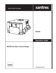
INPUT<br />
INV/CHG<br />
GFCI<br />
Fleet Power 2000 shown.<br />
5<br />
90-0115-00<br />
10/97 Fltman.pm65
OPERATION<br />
Power Switch<br />
The Power Switch is located on the<br />
front panel. This switch controls ON/OFF<br />
and RESET for the <strong>inverter</strong>. Expect a 3<br />
second delay when the <strong>power</strong> switch is<br />
turned ON before the unit is activated.<br />
If the unit is connected to external AC<br />
<strong>power</strong>, the <strong>battery</strong> charger and transfer<br />
switch will continue to function, regardless<br />
of the position of the switch.<br />
When external AC <strong>power</strong> is removed<br />
and the <strong>power</strong> switch is in the ON position,<br />
the <strong>inverter</strong> will automatically be ON. If the<br />
switch is in the OFF position and external<br />
AC <strong>power</strong> is removed, the <strong>inverter</strong> will be<br />
OFF.<br />
Inverter overload protection, transfer<br />
switching, <strong>power</strong> sharing and <strong>battery</strong><br />
charger reg<strong>ul</strong>ation will all function automatically.<br />
If installed with the remote control<br />
panel, the <strong>power</strong> switch on the unit sho<strong>ul</strong>d<br />
be left in the OFF position. Refer to Remote<br />
Control Panel, page 7.<br />
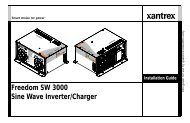
Power Switch<br />
Fleet Power 1000 shown.<br />
6<br />
90-0115-00<br />
10/97 Fltman.pm65
REMOTE CONTROL PANEL<br />
An optional remote control panel is<br />
available which offers several features not<br />
found on the unit. The remote control panel<br />
provides LED bargraphs which show system<br />
status, <strong>battery</strong> voltage, and DC Amps in<br />
both <strong>inverter</strong> and charge modes. These<br />
bargraphs can also display dip switch positions<br />
and shut down conditions.<br />
Remote Power Switch<br />
The switch on the remote is used to<br />
control the <strong>inverter</strong> and can also be used to<br />
control the <strong>battery</strong> charger function. When<br />
a remote control is used, the <strong>power</strong> switch<br />
on the <strong>inverter</strong> sho<strong>ul</strong>d be left in the OFF<br />
position.<br />
System Status LEDs<br />
These 4 LEDs monitor the system as<br />
described in the table on page 10.<br />
DC Volts Bargraph<br />
These LEDs indicate <strong>battery</strong> voltage as<br />
measured inside the unit. Each LED segment<br />
indicates .5 Volts. If an overload<br />
occurs and the unit shuts down, the DC<br />
Volts bargraph will stop indicating <strong>battery</strong><br />
voltage and display the dip switch settings.<br />
It will return to indicating <strong>battery</strong> voltage<br />
only after the unit has been reset.<br />
DC Amps Bargraph<br />
These LEDs approximate DC input<br />
current in <strong>inverter</strong> mode and DC output<br />
current in <strong>battery</strong> charger mode. Two<br />
ranges are used -- below 50 Amps each<br />
segment represents a 10 Amp increment,<br />
above 50 Amps each segment represents a<br />
20 Amp increment. Above 130 Amps, a<br />
flashing LED segment indicates the value<br />
displayed plus 100 Amps (flashing 50 LED<br />
is equal to 50 + 100 or 150 Amps DC).<br />
If a shutdown occurs, the DC Amps<br />
bargraph will stop indicating DC Amps and<br />
will indicate the type of problem . Each LED<br />
segment indicates a different problem as<br />
described in the troubleshooting section on<br />
page 34.<br />
7<br />
90-0115-00<br />
10/97 Fltman.pm65
REMOTE CONTROL PANEL<br />
Dip Switches<br />
On the back of the Fleet Power remote<br />
control panel is a set of 8 dip switches<br />
which are used to make several adjustments.<br />
On the switch block, each switch is<br />
numbered . . .1 through 8 and the ON position<br />
is indicated. The switch settings can be<br />
changed at any time, even while the unit is<br />
operating. Following is a discussion of<br />
each adjustment. Refer to the table on<br />
page 11 for dip switch programming.<br />
BACK VIEW<br />
Fleet Power Remote Control Panel<br />
SWITCH 1 - Manual Equalizing Cycling<br />
this switch ON for 1 second, then OFF,<br />
will initiate an equalizing charge cycle. The<br />
<strong>battery</strong> charger must be engaged before<br />
cycling the switch. The dip switch must<br />
always be returned to the OFF position.<br />
If it is left ON, an equalizing charge cycle<br />
will initiate every time the charger is<br />
engaged - this co<strong>ul</strong>d cause <strong>battery</strong> damage.<br />
The equalizing cycle is timed to last 8<br />
hours from the time the switch is cycled, at<br />
which point the charger resumes normal<br />
charging in the float stage.<br />
The <strong>battery</strong> LED blinks when equalizing.<br />
See page 18 for a discussion of the<br />
theory and procedure for <strong>battery</strong> equalizing.<br />
SWITCH #2 & #3 - Battery Type Gel cell<br />
and wet cell batteries have slightly different<br />
charge voltage requirements. Optimum<br />
<strong>battery</strong> charging is temperature dependent.<br />
For these reasons, the dip switches allow<br />
four different <strong>battery</strong> charger voltage set<br />
points, depending on <strong>battery</strong> type and<br />
ambient temperature:<br />
Cool Wet Cell < 80 degrees F.<br />
Warm Wet Cell > 80 degrees F.<br />
Cool Gel Cell < 80 degrees F.<br />
Warm Gel Cell > 80 degrees F.<br />
Refer to the table on page 21 for the<br />
specific voltages for each setting.<br />
SWITCH #4 - Auto Charge With the switch<br />
in the OFF position, the remote panel ON/<br />
OFF switch only controls the <strong>inverter</strong> operation.<br />
With the switch turned ON, it allows<br />
the <strong>power</strong> ON/OFF switch on the front of the<br />
remote to control the <strong>battery</strong> charger as well<br />
as the <strong>inverter</strong>.<br />
SWITCH #5 & #6 - Not used for adjustments.<br />
SWITCH #7 & #8 - Power Sharing These<br />
switches sho<strong>ul</strong>d be set to match the value of<br />
the circuit breaker which protects the incoming<br />
AC <strong>power</strong>. They may also limit the<br />
output current from the <strong>battery</strong> charger.<br />
8<br />
90-0115-00<br />
10/97 Fltman.pm65
REMOTE CONTROL PANEL<br />
Use the 5 Amp setting for small generators,<br />
or for charging deeply discharged<br />
batteries.<br />
Dip Switch Status<br />
You can check the position of the dip<br />
switches by quickly cycling the <strong>power</strong> switch<br />
OFF/ON twice. The DC Volts bargraph will<br />
cease to display <strong>battery</strong> voltage and will<br />
indicate the settings of each dip switch. In<br />
this mode the bottom LED will illuminate if<br />
switch 1 is on; the second LED will illuminate<br />
if switch 2 is on, etc. Dip switch settings<br />
are indicated for 10 seconds after<br />
which time the display returns to indicating<br />
<strong>battery</strong> voltage.<br />
Factory defa<strong>ul</strong>t settings for all dip<br />
switches are in the Off position.<br />
Remote Control Wiring<br />
The remote control panel is supplied<br />
with 25 or 50 ft. of telephone cable. The<br />
cable supplied may be 6 conductor, however,<br />
only 4 conductor is required. You may<br />
buy standard 4 conductor telephone cable<br />
and run up to 50 ft., if desired. Use only a<br />
single length of telephone wire, do not<br />
splice.<br />
Refer to page 11 for the Dip Switch<br />
Programming chart.<br />
9<br />
90-0115-00<br />
10/97 Fltman.pm65
STATUS LEDs<br />
Status LED<br />
INV/CHRG<br />
(Inverter/Charg<br />
AC Input<br />
Steady<br />
Overload<br />
Blinking<br />
Overload<br />
Steady Battery<br />
Blinking<br />
Battery<br />
Purpose<br />
Power on light. It will be illuminated whenever the<br />
<strong>power</strong> switch is on (<strong>inverter</strong> on) or when there is<br />
incoming AC <strong>power</strong> and the charger comes on.<br />
Illuminates when incoming AC <strong>power</strong> has been<br />
applied and the transfer relays have engaged.<br />
There is a 7-12 second delay from the time the AC<br />
is applied and this LED illuminates.<br />
Indicates an over-temperature condition, the unit is<br />
shut down. It will reset automatically after cooling.<br />
Inverter mode- Shutdown, diagnose problem using<br />
DC Amps bar graph. Charger mode- Thermal<br />
shutdown, after cooling reset by cycling <strong>power</strong><br />
switch.<br />
This is a High/Low Battery warning condition.<br />
Inverter mode: Battery > 15.25 or < 10.50 volts<br />
Charger mode: Battery > 15.25 or < 10.00 volts<br />
Indicates either a shutdown or equalizing.<br />
Battery > 15.50 volts, will auto-reset at 15.25.<br />
Inverter mode: Battery < 10.00 volts, will auto reset<br />
at charger float voltage or upon AC input.<br />
Charger mode: Battery < 8.00 volts for 1 minute,<br />
remove all DC loads and <strong>manual</strong>ly reset by cycling<br />
the disconnecting <strong>power</strong> switch. and reapplying shore<strong>power</strong>.<br />
10<br />
90-0115-00<br />
10/97 Fltman.pm65
DIP SWITCH PROGRAMMING<br />
Feature<br />
Switch<br />
Number<br />
Set Point<br />
Equalize or<br />
3 Stage<br />
Charging<br />
1<br />
Toggle<br />
On/Off<br />
Equalize (Do not leave on.)<br />
Off 3 Stage Charging*<br />
2 3<br />
Battery<br />
Type<br />
On On Warm Gel Cell (>80 deg. F.)<br />
Off On Cool Gel Cell (80 deg. F.)<br />
Off Off Cool Wet Cell (
BATTERIES<br />
BATTERY TYPES<br />
Use only deep-cycle batteries with your<br />
Fleet Power Inverter/Charger. These fall<br />
into two broad categories, wet cell and gel<br />
cell.<br />
Wet Cell Batteries<br />
True deep-cycle wet cell batteries are<br />
characterized by relatively thick plates that<br />
are alloyed with antimony.<br />
Common marine/RV deep-cycle<br />
batteries are acceptable. However, golf<br />
cart batteries have better performance and<br />
life. They are 6 Volt batteries that must be<br />
used in series pairs. High quality marine<br />
deep-cycle batteries offer good performance<br />
and are available in a wide variety<br />
of sizes. Floor sweeper, fork lift or large 2<br />
Volt cells can also offer excellent performance,<br />
if their large size can be accommodated.<br />
It sho<strong>ul</strong>d be noted that high antimony<br />
deep-cycle batteries will give off gas as a<br />
natural res<strong>ul</strong>t of charging and will experience<br />
some water loss. It is very important<br />
that the electrolyte level be checked<br />
frequently and topped off with distilled<br />
water when necessary. Never allow the<br />
tops of the plates to be exposed to air, as<br />
contamination of the cell will res<strong>ul</strong>t. Keeping<br />
the tops of batteries clean will reduce<br />
self-discharging. Always provide ventilation<br />
for the <strong>battery</strong> storage compartment.<br />
Do not use car batteries or engine<br />
starting batteries of any kind with your<br />
<strong>inverter</strong>/charger. Beware of any <strong>battery</strong> that<br />
is rated in Cold Cranking Amps (CCA). This<br />
is a rating which applies only to engine<br />
starting batteries. In general, most wet cell<br />
batteries that are described as hybrid batteries,<br />
suitable for either engine starting or<br />
deep-cycle applications, are a compromise<br />
and will give limited life if deeply discharged.<br />
Beware of 8-D starting batteries that<br />
are commonly used for starting diesel engines.<br />
These batteries are not deep-cycle.<br />
12<br />
90-0115-00<br />
10/97 Fltman.pm65
BATTERIES<br />
Beware of so-called maintenancefree<br />
batteries. These batteries have calcium<br />
alloyed with the lead and hold the<br />
liquid electrolyte in a sponge-like material.<br />
They are sealed and water cannot be<br />
added. Do no confuse them with true gel<br />
cell batteries, they will not hold up to deep<br />
discharging.<br />
Gel Cell Batteries<br />
Gel cell batteries are lead-acid batteries<br />
similar in many ways to the common wet<br />
cell <strong>battery</strong>, but differences in the chemistry<br />
and construction provide some unique<br />
features.<br />
No Maintenance - There is no need to<br />
add water and the tops of the batteries stay<br />
clean. Also, the batteries can be used in<br />
any position and may be used without a<br />
<strong>battery</strong> box.<br />
Low Self-Discharging - Unlike wet cell<br />
batteries, the gel cell will hold its charge for<br />
months if left sitting with no load and no<br />
float charge. They can be stored without a<br />
constant float charge and without fear of<br />
freezing.<br />
Low Internal Resistance - The res<strong>ul</strong>t<br />
of low internal resistance is a higher <strong>battery</strong><br />
voltage under load, which will res<strong>ul</strong>t in<br />
better <strong>inverter</strong> performance on demanding<br />
high <strong>power</strong> loads. In addition, this allows<br />
the gel cell to accept a high rate of charge,<br />
a plus for rapid recharging.<br />
The features of the gel cell batteries<br />
solve many common problems. Cycle life is<br />
high, even under constant deep discharging.<br />
BATTERY INTERCONNECTION<br />
In most cases you will be using a bank<br />
of two or more batteries with your <strong>inverter</strong>/<br />
charger. You may connect batteries together<br />
in two configurations, series and<br />
parallel.<br />
Series<br />
Connecting 2 batteries in series will<br />
double the voltage of the <strong>battery</strong> bank. For<br />
instance, two 6 Volt batteries connected in<br />
series will produce 12 Volts. The Amp-hour<br />
capacity of the <strong>battery</strong> bank will be the<br />
same as each individual <strong>battery</strong>. Example,<br />
two 6 Volt 220 Amp-hour batteries in series<br />
will produce on 12 Volt 220 Amp-hour <strong>battery</strong><br />
bank.<br />
-<br />
-<br />
+<br />
+<br />
Series<br />
13<br />
90-0115-00<br />
10/97 Fltman.pm65
BATTERIES<br />
Parallel<br />
Connecting 2 batteries in parallel will<br />
double the Amp-hour rating of the <strong>battery</strong><br />
bank, while the voltage will be the same as<br />
each individual <strong>battery</strong>. Example, two 12<br />
Volt 105 Amp-hour batteries in parallel will<br />
produce one 12 Volt 210 Amp-hour <strong>battery</strong><br />
bank.<br />
+<br />
+<br />
-<br />
-<br />
Parallel<br />
Only similar batteries sho<strong>ul</strong>d be<br />
connected together in one bank. Do not<br />
connect old and new batteries together or<br />
wet and gel cell batteries together. In the<br />
above drawing, the load is connected to the<br />
positive terminal of the first <strong>battery</strong> and the<br />
negative terminal of the last <strong>battery</strong>. This<br />
practice helps to balance the <strong>battery</strong> bank<br />
and is called cross connecting the <strong>battery</strong><br />
bank.<br />
Always use proper terminals for your<br />
interconnecting <strong>battery</strong> cables which are<br />
appropriate to handle the current.<br />
Battery Bank Ratings and Sizing<br />
Deep-cycle batteries are usually rated<br />
in Amp-hours. The Amp-hour rating is<br />
based on a 20 hour discharge cycle, therefore,<br />
a 100 Amp-hour <strong>battery</strong> can deliver 5<br />
Amps for 20 hours. If the discharge rate is<br />
greater than 5 Amps, the available Amphours<br />
are decreased. If the load is increased<br />
to 100 Amps, only about 45 Amphours<br />
will be available at this rate of discharge.<br />
Another common rating is reserve<br />
capacity expressed in minutes. This is<br />
derived by placing a 25 Amp load on the<br />
<strong>battery</strong> and measuring the time until the<br />
<strong>battery</strong> voltage reaches 10.5 Volts.<br />
Deep-cycle batteries can be discharged<br />
about 80% before permanent damage<br />
occurs, though shallower cycling will res<strong>ul</strong>t<br />
in much longer <strong>battery</strong> life. 50% cycling is<br />
generally considered to be a good compromise<br />
between long <strong>battery</strong> life and a reasonably<br />
sized <strong>battery</strong> bank.<br />
14<br />
90-0115-00<br />
10/97 Fltman.pm65
BATTERIES<br />
To achieve 50% cycling you sho<strong>ul</strong>d<br />
calc<strong>ul</strong>ate your Amp-hour consumption<br />
between charging cycles and use a <strong>battery</strong><br />
bank with twice that capacity.<br />
To calc<strong>ul</strong>ate Amp-hour consumption first<br />
look at the rating plate on your AC appliance<br />
or tools. Each appliance or tool will be<br />
rated in either AC Amps or AC watts or AC<br />
VA (Volts-Amps) apparent <strong>power</strong>. Use one<br />
of the following form<strong>ul</strong>as to calc<strong>ul</strong>ate the DC<br />
Amp-hour draw for a 12 Volt system:<br />
(AC Amps x 10) x 1.1 x hours of<br />
operation = DC Amp-hours<br />
(AC watts/12) x 1.1 x hours of operation<br />
= DC Amp-hours<br />
(AC VA/12) x 1.1 x hours of operation =<br />
DC Amp-hours<br />
In all form<strong>ul</strong>as, 1.1 is the factor for<br />
<strong>inverter</strong> efficiency.<br />
Calc<strong>ul</strong>ate the above for every AC<br />
appliance or tool you intend to use on your<br />
<strong>inverter</strong>. This will give you the total number<br />
of Amp-hours used between recharges.<br />
Size your <strong>battery</strong> bank using this number as<br />
a guideline. A good r<strong>ul</strong>e to follow is to size<br />
the <strong>battery</strong> bank about 2 times larger than<br />
your total Amp-hour load requirement. Plan<br />
on recharging when 50% discharged.<br />
Typical PowerConsumption<br />
Loads<br />
On-Board Computers<br />
Quartz Halogen Flood<br />
0.2 HP Bench Grinder<br />
Hammer Drill<br />
3/8" Electric Drill Motor<br />
Sawzall<br />
0.5 HP Bench Grinder<br />
1.0 HP Tile Saw<br />
0.5 HP Skil ® Saw<br />
2.0 HP Radial Arm Saw<br />
2.5 HP Chain Saw<br />
Hand Blower/Vacuum<br />
Quartz Halogen Flood<br />
11 gal. Air Compressor<br />
Chain Saw<br />
20 gal. Air Compressor<br />
10" Table Saw<br />
10" Miter Saw<br />
Planer<br />
Coring System<br />
Watts<br />
200<br />
300<br />
300<br />
500<br />
500<br />
500<br />
750<br />
800<br />
1200<br />
1200<br />
1200<br />
1450<br />
1500<br />
1600<br />
1700<br />
1800<br />
1800<br />
1800<br />
1800<br />
2000<br />
Many electric motors have momentary<br />
starting requirements well above their operational<br />
rating. Start up watts are listed<br />
where appropriate. Individual styles and<br />
brands of appliances may vary.<br />
15<br />
90-0115-00<br />
10/97 Fltman.pm65
BATTERY CHARGING<br />
Battery Charging<br />
Completely recharging wet cell deepcycle<br />
batteries requires the <strong>battery</strong> voltage<br />
to be raised beyond what is known as the<br />
gassing point. This is the voltage at which<br />
the <strong>battery</strong> begins to bubble and gas is<br />
given off. If charging stops short of this<br />
point, s<strong>ul</strong>fate is left on the plates and deterioration<br />
of the <strong>battery</strong> begins. The gassing<br />
point will vary with <strong>battery</strong> temperature.<br />
Gel cell batteries must not be charged<br />
to their gassing point. In fact, high voltage<br />
charging which gasses these batteries is<br />
harmf<strong>ul</strong> to them. They typically require a<br />
lower b<strong>ul</strong>k charge voltage and a higher float<br />
voltage. Cons<strong>ul</strong>t the <strong>battery</strong> manufacturer<br />
for specifications.<br />
Conventional Battery Chargers<br />
Most conventional <strong>battery</strong> <strong>chargers</strong> are<br />
single-stage constant voltage <strong>chargers</strong>.<br />
They must stop short of the gassing point or<br />
they will overcharge the <strong>battery</strong> bank.<br />
Therefore, most 12 volt <strong>battery</strong> <strong>chargers</strong><br />
bring the <strong>battery</strong> voltage up to about 13.8<br />
Volts.<br />
This presents two problems. First,<br />
since the <strong>battery</strong> voltage does not reach the<br />
gassing point, s<strong>ul</strong>fate is left on the plates.<br />
Second, 13.8 volts is close enough to the<br />
gassing point that some gas will escape,<br />
and the wet cell <strong>battery</strong> will need to be<br />
frequently topped off with distilled water.<br />
Conventional <strong>battery</strong> <strong>chargers</strong> also<br />
suffer from another inherent characteristic of<br />
design, which is a tapering output. While<br />
they will deliver their rated current into a<br />
deeply discharged <strong>battery</strong>, as the <strong>battery</strong><br />
becomes charged and the voltage rises, the<br />
output current of the charger tapers down.<br />
This taper continues as the <strong>battery</strong> is<br />
charged, taking a very long time to reach an<br />
acceptable recharge.<br />
Fleet Power Battery Chargers<br />
Fleet Power <strong>battery</strong> <strong>chargers</strong> are designed<br />
to overcome the limitations of conventional<br />
<strong>chargers</strong> by utilizing 3 distinct<br />
stages, each designed for optimal recharging<br />
of both wet cell and gel cell deep-cycle<br />
batteries.<br />
16<br />
90-0115-00<br />
10/97 Fltman.pm65
BATTERY CHARGING<br />
NOTE: Fleet Power <strong>battery</strong> <strong>chargers</strong> are on<br />
whenever there is AC <strong>power</strong> connected to<br />
the charger input, regardless of the condition<br />
of the On/Off switch. This feature can<br />
be disabled by setting the dip switch #4<br />
(back of the remote) to "On" so that the<br />
charger will also be controlled by the On/Off<br />
switch.<br />
Each time the <strong>battery</strong> charger is engaged,<br />
the 3 stages proceed automatically,<br />
res<strong>ul</strong>ting in an efficient, complete recharge<br />
and safe <strong>battery</strong> maintenance. Use of the<br />
remote control provides the ability to periodically<br />
apply an 8-hour timed equalizing<br />
charge.<br />
The <strong>battery</strong> charger stages are:<br />
Stage 1 - B<strong>ul</strong>k Charge During the b<strong>ul</strong>k<br />
charge stage most of the charge current is<br />
delivered to the <strong>battery</strong> bank. This phase is<br />
engaged as soon as the <strong>battery</strong> charger is<br />
activated. F<strong>ul</strong>l rated charger current is<br />
delivered to the <strong>battery</strong> bank until the b<strong>ul</strong>k<br />
charge voltage limit is reached. This res<strong>ul</strong>ts<br />
in a relatively rapid recharge.<br />
Generally, a wet cell <strong>battery</strong> bank<br />
sho<strong>ul</strong>d not be charged up to the gassing<br />
point at a rate which exceeds 25% of its<br />
capacity. In other words, a 12 volt <strong>battery</strong><br />
bank of 520 Amp-hours sho<strong>ul</strong>d not be<br />
charged at over 130 Amps.<br />
17<br />
90-0115-00<br />
10/97 Fltman.pm65
BATTERY CHARGING<br />
Gel cell batteries can accept a higher<br />
rate of charge. Cons<strong>ul</strong>t the manufacturer for<br />
specifications.<br />
Stage 2 - Acceptance Charge The<br />
acceptance stage immediately follows the<br />
b<strong>ul</strong>k charge stage. During this stage the<br />
<strong>battery</strong> voltage is held constant at the b<strong>ul</strong>k<br />
charge voltage limit and the current gradually<br />
ramps down. During this stage the<br />
<strong>battery</strong> is accepting its final amount of<br />
charge current and the last of the s<strong>ul</strong>fate on<br />
the plates is removed.<br />
The acceptance stage lasts until the<br />
charge current reaches about 6-7 Amps. A<br />
timer will terminate the acceptance stage if<br />
this current level is not reached. This timer<br />
is set automatically when the dip switches<br />
for <strong>battery</strong> type are set. Maximum acceptance<br />
time is 1 hour for wet cells and 3<br />
hours for gel cells. Gel cell acceptance time<br />
can be increased because the <strong>battery</strong> is not<br />
gassing. Expect wet cell batteries to gas<br />
somewhat during acceptance, this is a<br />
necessary part of the charging process.<br />
Stage 3 - Float Charge When the<br />
acceptance stage is terminated, either<br />
because the charge current ramped down to<br />
6-7 Amps or the timer engaged, <strong>battery</strong><br />
charger current will shut off. The unit monitors<br />
the <strong>battery</strong> voltage while it drifts down<br />
from the b<strong>ul</strong>k charge voltage limit. When it<br />
reaches the float voltage set point, the float<br />
charge stage is engaged.<br />
The float charge stage holds the <strong>battery</strong><br />
voltage at a lower level, where it is safe for<br />
long term <strong>battery</strong> maintenance. During the<br />
float charge stage, the f<strong>ul</strong>l output current of<br />
the <strong>battery</strong> charger is available to operate<br />
any DC appliances that may be on the<br />
system, while constantly maintaining the<br />
float charge voltage.<br />
The <strong>battery</strong> charger remains in the float<br />
charge stage indefinitely until the charger is<br />
disconnected from incoming AC <strong>power</strong>.<br />
Stage 4 - Equalizing Charge This is<br />
the only <strong>battery</strong> charger stage which is not<br />
engaged automatically. It must be <strong>manual</strong>ly<br />
initiated each time it is necessary to equalize<br />
using a dip switch on the back of the<br />
remote control. Applying an equalizing<br />
charge is not possible without the use of a<br />
remote.<br />
Periodic equalizing is recommended by<br />
most wet cell deep-cycle <strong>battery</strong> manufacturers.<br />
There are no firm r<strong>ul</strong>es for how often<br />
an equalizing charge sho<strong>ul</strong>d be applied, but<br />
once a month is a good r<strong>ul</strong>e of thumb for<br />
batteries which are reg<strong>ul</strong>arly cycled, less<br />
often for systems in only occasional use.<br />
The equalizing charge is a timed, 8-<br />
hour cycle. If desired, it can be ended by<br />
interrupting the AC <strong>power</strong> to the charger at<br />
any time during the cycle. Equalizing<br />
sho<strong>ul</strong>d be engaged after the batteries have<br />
been f<strong>ul</strong>ly charged by a normal <strong>battery</strong><br />
18<br />
90-0115-00<br />
10/97 Fltman.pm65
BATTERY CHARGING<br />
charging cycle. The <strong>battery</strong> voltage will<br />
increase to 16.3 using the cool temperature<br />
wet cell setting. This will cause the <strong>battery</strong><br />
bank to gas profusely and will accomplish<br />
the following:<br />
1. Removal of residual s<strong>ul</strong>fate. Each time<br />
a <strong>battery</strong> is cycled (discharged and recharged),<br />
a small amount of s<strong>ul</strong>fate is left on<br />
the plates. Over time, this gradual build-up<br />
of s<strong>ul</strong>fate will compromise the performance<br />
of the <strong>battery</strong>. By applying an equalizing<br />
charge, the s<strong>ul</strong>fate is returned back to the<br />
electrolyte, raising the specific gravity and<br />
f<strong>ul</strong>ly exposing the active material of the<br />
plates.<br />
2. Bring all cells to the same potential.<br />
All lead-acid batteries are made up of individual<br />
2 Volt cells. As the <strong>battery</strong> bank is<br />
cycled, slight differences in the cells res<strong>ul</strong>t<br />
in different cell voltages, affecting the overall<br />
charge effectiveness. Equalizing brings<br />
all cells up to the same voltage and the<br />
electrolyte in each cell to the same specific<br />
gravity.<br />
3. Mixing up of the electrolyte. Electrolyte<br />
in <strong>battery</strong> cells tend to separate into<br />
layers of acid and water. The vigorous<br />
boiling action of the <strong>battery</strong> during equalizing<br />
serves to physically mix the electrolyte.<br />
Equalizing is not required on gel cell<br />
batteries. You will note that if the dip<br />
switches are set in one of the two gel cell<br />
positions, the equalizing charge voltage is<br />
the same as the b<strong>ul</strong>k charge voltage, therefore,<br />
equalizing is equivalent to an 8-hour<br />
acceptance stage and is not harmf<strong>ul</strong>.<br />
To limit the DC current during equalizing<br />
to less than 15 Amps, turn on dip<br />
switches 7 and 8 before starting the equalize<br />
charge. Do not operate AC loads that<br />
are on the output of the <strong>inverter</strong>/charger<br />
when equalizing.<br />
Charging Over-Discharged Batteries<br />
Charging into a <strong>battery</strong> bank with a<br />
terminal voltage of less than 8 Volts presents<br />
a special problem for the unit. If this<br />
situation arises, the unit will attempt to<br />
charge for 1 minute. If the <strong>inverter</strong> senses<br />
excessive ripple voltage, it will shut down to<br />
protect itself.<br />
To successf<strong>ul</strong>ly charge an overdischarged<br />
<strong>battery</strong>, you must remove as<br />
much DC load as possible. Set dip<br />
switches 7 and 8 to the ON position to limit<br />
the amount of charge current and the res<strong>ul</strong>ting<br />
ripple voltage. After the <strong>battery</strong> voltage<br />
has reached 10 Volts, these switches can<br />
be set to their previous positions.<br />
19<br />
90-0115-00<br />
10/97 Fltman.pm65
BATTERY CHARGING<br />
WARNINGS<br />
1. Do not equalize gel cell batteries<br />
with the remote programmed for wet<br />
cells.<br />
2. Always monitor the equalize<br />
charge. Provide proper ventilation for<br />
<strong>battery</strong> fumes. Do not allow any sparks<br />
during equalizing. If one or more cells<br />
begin to overflow, terminate the equalize<br />
charge.<br />
3. Check and top off the <strong>battery</strong> electrolyte<br />
both before and after the<br />
equalizing charge. Do not expose the<br />
<strong>battery</strong> plates to air. Leave the <strong>battery</strong><br />
caps on while equalizing.<br />
4. Remove all loads from the DC system<br />
before equalizing. Some DC loads<br />
may not tolerate the high charge voltage.<br />
5. Do not leave the equalize dip<br />
switch in the ON position. It must be<br />
cycled OFF and left in the OFF position.<br />
If left ON, the unit will engage the equalizing<br />
cycle every time the <strong>battery</strong> charger<br />
is engaged.<br />
Note: If a continuous DC load in excess<br />
of the charge rate is placed on the<br />
<strong>battery</strong> bank, eventually the <strong>battery</strong> voltage<br />
will drop below 8 Volts and the <strong>battery</strong><br />
charger will shut off. This load must be<br />
significantly reduced and the <strong>power</strong> to the<br />
charger cycled to resume charging.<br />
Blinking of the <strong>battery</strong> LED on the<br />
remote control while charging is a warning<br />
that an over-discharge is imminent and that<br />
the DC load sho<strong>ul</strong>d be reduced.<br />
NOTE: Equalize only after a reg<strong>ul</strong>ar<br />
charge cycle.<br />
20<br />
90-0115-00<br />
10/97 Fltman.pm65
BATTERY CHARGER VOLTAGE SETTINGS<br />
Battery Type and<br />
Temperature<br />
B<strong>ul</strong>k Voltage/<br />
Max Time<br />
Float<br />
Voltage<br />
Equalize<br />
Voltage<br />
12 Volt Wet Cell<br />
Warm Temperature<br />
12 Volt Wet Cell<br />
Cool Temperature<br />
12 Volt Gel Cell<br />
Warm Temperature<br />
12 Volt Gel Cell<br />
Cool Temperature<br />
14.0<br />
/ 1 hr 13.<br />
1<br />
15. 8<br />
14.4<br />
/ 1 hr 13.<br />
5<br />
16. 3<br />
13.8<br />
/ 3 hr 13.<br />
3<br />
13. 8<br />
14.1<br />
/ 3 hr 13.<br />
6<br />
14. 1<br />
21<br />
90-0115-00<br />
10/97 Fltman.pm65
INSTALLATION PRECAUTIONS<br />
CAUTION This equipment is not ignition<br />
protected and employs components<br />
that tend to produce arcs or<br />
sparks. To reduce the risk of fire or<br />
explosions, do not install in compartments<br />
containing batteries or flammable<br />
materials or areas in which<br />
ignition-protected equipment is required.<br />
WARNING<br />
For continued protection against risk of<br />
electric shock, use only the groundfa<strong>ul</strong>t<br />
circuit interrupter (GFCI) type<br />
receptacles detailed in this <strong>owner's</strong><br />
<strong>manual</strong>. Other types may fail to operate<br />
properly when connected to this <strong>inverter</strong>,<br />
res<strong>ul</strong>ting in a potential shock hazard.<br />
CAUTION Risk of electrical shock. Both<br />
AC & DC voltage sources are terminated<br />
inside this equipment. Each circuit must<br />
be individually opened before servicing.<br />
CAUTION Risk of electrical shock. Do<br />
not remove cover, no user serviceable<br />
parts inside. Refer servicing to qualified<br />
service personnel.<br />
APPLICATION INFORMATION Provided<br />
with integral electronic protection<br />
against AC & DC overloads.<br />
AC Inputs<br />
AC Output<br />
Remote<br />
Jack<br />
CAUTION To reduce the risk of electric<br />
shock and prevent premature failure due to<br />
corrosion, do not mount where exposed<br />
to rain or spray.<br />
CAUTION To prevent fire, do not obstruct<br />
ventilation openings. Do not mount in a<br />
zero clearance compartment, overheating<br />
may res<strong>ul</strong>t.<br />
NOTICE The output of this device is not<br />
sinusoidal. It has a maximum total harmonic<br />
distortion of 47% and a maximum<br />
single harmonic of 34%.<br />
Chassis<br />
Ground<br />
Lug<br />
Fleet Power 2500 shown.<br />
22<br />
90-0115-00<br />
10/97 Fltman.pm65
INSTALLATION<br />
Key Installation Points<br />
The Power Switch must be turned OFF<br />
before you begin.<br />
1. Observe proper polarity when<br />
connecting batteries. Reverse DC polarity<br />
will res<strong>ul</strong>t in damage to the unit and will void<br />
the warranty. Use care when making the<br />
DC connections.<br />
2. Do not back-feed the AC output of<br />
the <strong>inverter</strong> with incoming AC <strong>power</strong>. A<br />
back-feed occurs when AC <strong>power</strong> from<br />
shore <strong>power</strong> or generator is connected to<br />
the output of the <strong>inverter</strong>. This will damage<br />
the <strong>inverter</strong> and void the warranty. Remember<br />
that incoming AC must be fed only to<br />
the AC input and never to the AC output.<br />
Always check for AC voltage before connecting<br />
wires to the AC output. Do NOT<br />
turn the <strong>inverter</strong> ON until all AC connections<br />
have been made. Back-feeding the <strong>inverter</strong><br />
voids the warranty.<br />
3. Do not connect the AC input to the<br />
AC output. In effect, this wo<strong>ul</strong>d be plugging<br />
the <strong>battery</strong> charger into the <strong>inverter</strong>.<br />
This co<strong>ul</strong>d occur if the unit is connected to<br />
the entire leg of a circuit breaker panel, then<br />
a circuit breaker on that leg is used to feed<br />
the <strong>battery</strong> charger. This will cause the unit<br />
to oscillate ON and OFF when the unit is in<br />
<strong>inverter</strong> mode.<br />
4. Always use proper wire and connectors.<br />
The proper <strong>battery</strong> cable size is<br />
critical because considerable amperage<br />
flows in the DC circuit. Fusing the positive<br />
DC cable is required. The AC wire size is<br />
dependant on potential current in the circuit.<br />
Cons<strong>ul</strong>t the NEC (National Electric Code)<br />
for proper wire gauge.<br />
5. Keep the <strong>inverter</strong>/charger out of<br />
the elements and out of direct contact<br />
with water or spray. Remember that the<br />
unit is a piece of electronic equipment and<br />
treat it accordingly.<br />
6. Mount the unit as close to the<br />
batteries as possible but not in the presence<br />
of flammable fumes or in an enclosed<br />
<strong>battery</strong> compartment.<br />
7. The connectors for the remote<br />
control and the chassis ground bonding<br />
lug, as well as for the AC wires, are located<br />
on the bottom of the unit. Be sure<br />
to make these connections before bolting<br />
the unit down.<br />
8. You may mount the unit horizontally<br />
(on a shelf) or vertically (on a wall or<br />
b<strong>ul</strong>khead). If mounted vertically, you must<br />
orient the unit so the switch and the circuit<br />
breakers are facing up and the fan and<br />
<strong>battery</strong> cables are facing down.<br />
9. Allow several inches of clearance<br />
around the unit and allow for a supply of<br />
fresh air to the cooling fan. Do not block<br />
any of the vents or louvers. The fan p<strong>ul</strong>ls<br />
air from outside the unit. It blows air across<br />
the internal components, partic<strong>ul</strong>arly the<br />
transformer and heat sinks, then out the<br />
side vents.<br />
23<br />
90-0115-00<br />
10/97 Fltman.pm65
INSTALLATION<br />
10. If installing in a system which includes<br />
an existing <strong>battery</strong> charger or converter,<br />
make sure these do not operate<br />
from the <strong>inverter</strong> output AC <strong>power</strong>. This<br />
sets up a <strong>power</strong> loop which, due to inefficiencies,<br />
will quickly drain the batteries.<br />
11. Make sure all wiring conforms to<br />
local and national electrical codes. If in<br />
doubt, cons<strong>ul</strong>t with a qualified electrician.<br />
12. Keep the overall length of each<br />
<strong>battery</strong> cable less than 10 feet. If needed,<br />
attach short extension cables. Do not use<br />
frame ground or a ground bonding system<br />
as a current carrying conductor. Run the<br />
negative cable directly to the <strong>battery</strong> bank.<br />
If the positive and negative cables run<br />
parallel to each other, twist the cables<br />
together. This will minimize the adverse<br />
effects of inductance.<br />
13. To meet electrical codes, a fuse<br />
must be installed in the positive <strong>battery</strong><br />
cable within 18 inches of the <strong>battery</strong> post.<br />
This fuse is intended to protect the <strong>battery</strong><br />
and cables against a dead short circuit.<br />
The <strong>inverter</strong> is protected internally and will<br />
not blow a properly sized fuse.<br />
14. DC wiring is generally very simple,<br />
the positive and negative cables from the<br />
<strong>inverter</strong>/charger are connected to the house<br />
or auxiliary <strong>battery</strong>. In the case of m<strong>ul</strong>tiple<br />
batteries the interconnecting jumper cables<br />
must be of the same AWG as those supplied<br />
with the <strong>inverter</strong>/charger.<br />
15. If m<strong>ul</strong>tiple <strong>battery</strong> banks are to be<br />
charged, a <strong>battery</strong> selector switch can be<br />
installed, allowing the banks to be charged<br />
either individually or sim<strong>ul</strong>taneously. A<br />
solenoid can also be used.<br />
WARNING<br />
Do not mount the unit in an enclosed<br />
<strong>battery</strong> compartment. Take precautions<br />
to keep road dirt and spray off the unit.<br />
Grounding<br />
For safety purposes, the chassis of<br />
the <strong>inverter</strong>/charger must be connected<br />
to your AC ground system. The chassis<br />
ground bonding lug is located on the bottom<br />
of the unit. This connector can accept two<br />
wires, the first is used to connect the unit to<br />
AC ground, the second can be used to<br />
connect other AC equipment to ground.<br />
Use bare copper ins<strong>ul</strong>ated wire, solid or<br />
stranded. Strip one end and use a screwdriver<br />
to secure it to the chassis ground<br />
bonding lug. This wire will connect to the<br />
ground in your AC electrical system, typically<br />
the vehicle chassis. Make sure the<br />
connection is clean and tight.<br />
24<br />
90-0115-00<br />
10/97 Fltman.pm65
INSTALLATION<br />
This procedure will connect the chassis<br />
of your unit to AC ground. In addition, the<br />
AC input and AC output green wires are<br />
connected to chassis ground. It is important<br />
to connect these wires to the AC ground bus<br />
in the circuit breaker panel.<br />
Note: The <strong>battery</strong> cables are not connected<br />
to ground or the chassis of the unit.<br />
Neutral Bonding<br />
For safety purposes, the Fleet Power<br />
<strong>inverter</strong>/charger unit internally bonds the AC<br />
output neutral to the AC ground when the<br />
unit is OFF or in the <strong>inverter</strong> mode. When<br />
incoming AC <strong>power</strong> is applied and the<br />
transfer switch is engaged, the internal<br />
neutral-to- ground bond is automatically<br />
lifted.<br />
This means that when the vehicle is<br />
connected to shore <strong>power</strong>, the grounding<br />
system is connected to the shore <strong>power</strong><br />
ground, where neutral and earth ground are<br />
bonded together. This technique insures<br />
safety in all conditions and conforms to the<br />
requirements of the NEC.<br />
AC Wiring<br />
The AC wires route through the holes in<br />
the bottom of the unit. Use a screwdriver to<br />
remove the screws which secure the AC<br />
wiring compartment cover plate. Inside, the<br />
compartment is divided into 2 sections, one<br />
labeled AC Input, the other labeled AC<br />
Output. Each side contains 3 pigtails:<br />
black, white and green. Six wire nut connectors<br />
are also provided.<br />
Black<br />
Hot or Line<br />
White<br />
Neutral<br />
Green Ground<br />
Conventional metal strain reliefs are<br />
provided. These can be replaced by plastic<br />
strain reliefs for additional corrosion resistance<br />
or 3/4 inch conduit fittings if the wiring<br />
will be routed through the conduit.<br />
Use proper wire sizes according to the<br />
NEC.<br />
AC Input (Fleet Power 1000 and Fleet<br />
Power 2000): Feed the 3 conductor AC<br />
input wire through the strain relief and into<br />
the AC input compartment. You sho<strong>ul</strong>d<br />
have 6 inches of individually ins<strong>ul</strong>ated<br />
black, white and green wire. Strip 1/2 inch<br />
of ins<strong>ul</strong>ation off each conductor and connect<br />
to the pigtails: black to black, white to white<br />
and green to green.<br />
AC Input (Fleet Power 2500): There<br />
are 2 options for configuring the AC input to<br />
the Fleet Power 2500.<br />
Dual Inputs: The internal <strong>battery</strong><br />
charger may be fed separately from the<br />
transfer input which feeds the AC loads. In<br />
this case, connect one 30 Amp feed to the<br />
charger pigtails and another 30 Amp feed to<br />
the transfer switch input.<br />
Connecting the feeds in this way balances<br />
the AC loads when 2 legs of incoming<br />
AC <strong>power</strong> are available. These two feeds<br />
can be in or out of phase. Transfer will only<br />
25<br />
90-0115-00<br />
10/97 Fltman.pm65
INSTALLATION<br />
Do not connect incoming AC from any<br />
source to the AC output of the <strong>inverter</strong>/<br />
charger. This is known as back-feeding<br />
and will damage the unit and void the<br />
warranty.<br />
90-0115-00<br />
10/97 Fltman.pm65<br />
WARNING<br />
occur when <strong>power</strong> is applied to both inputs.<br />
The charger can draw up to 27 Amps on<br />
one leg of <strong>power</strong> and the transfer switch can<br />
pass up to 30 Amps from the other leg of<br />
<strong>power</strong>.<br />
Single Input: Both the <strong>battery</strong> charger<br />
and the transfer switch may be fed from the<br />
same AC input. In this case, connect both<br />
pigtails together, black to black, white to<br />
white and green to green.<br />
This allows up to 60 Amps of AC <strong>power</strong><br />
to be brought in on a single cable. Up to 30<br />
Amps is available to the loads, with the<br />
balance available to <strong>power</strong> the <strong>battery</strong><br />
charger. A single cable sho<strong>ul</strong>d be protected<br />
by a 60 Amp breaker or smaller, and 6<br />
gauge wire sho<strong>ul</strong>d be used.<br />
AC Output: On the Fleet Power 1000,<br />
AC output is available at the GFCI outlet<br />
mounted on the unit. On the Fleet Power<br />
2000, AC output is available at both the<br />
GFCI outlet and at the AC output compartment.<br />
The AC output for the Fleet Power<br />
2500 is available at the AC output compartment<br />
only. When installing the Fleet Power<br />
2000 and 2500, feed the 3 conductor AC<br />
output wire through the strain relief and<br />
26<br />
connect in the same fashion as the AC input<br />
wires.<br />
If you are not connecting the hardwire<br />
output wires (Fleet Power 2000 only), make<br />
certain they can not cause a short circuit to<br />
the wiring compartment. Tug firmly on each<br />
connection to make sure they are secure.<br />
Check these connections first if the unit is<br />
not operating properly.<br />
Caref<strong>ul</strong>ly tuck the wires into the AC<br />
wiring compartment. Replace cover plate.<br />
Ground Fa<strong>ul</strong>t Circuit Interrupters<br />
In order to conform to the NEC, certain<br />
branch circuits must be equipped with a<br />
Ground Fa<strong>ul</strong>t Circuit Interrupter (GFCI).<br />
Please cons<strong>ul</strong>t the code or a qualified<br />
electrician for details. Any such branch<br />
circuit must be protected by a circuit<br />
breaker consistent with the GFCI rating.<br />
Underwriters Laboratories has tested the<br />
following GFCI, and its use is recommended.<br />
Receptacle Type:<br />
Pass & Seymour<br />
Catalog Number 1591-RW<br />
Rated: 15 Amps at 120 Volts AC<br />
Fleet Power 1000 and 2000 <strong>inverter</strong>/<br />
<strong>chargers</strong> provide an integral GFCI outlet<br />
which is protected by a circuit breaker. This<br />
GFCI outlet does not protect the hardwire<br />
AC output. The hardwire AC output is<br />
protected by a non-GFCI circuit breaker on<br />
the Fleet Power 2000 only. The first outlet<br />
from the hardwire output sho<strong>ul</strong>d be GFCI<br />
protected to comply with applicable codes<br />
and standards.<br />
The GFCI Receptacle is designed to<br />
protect from line-to-ground shock hazards<br />
which co<strong>ul</strong>d occur from defective <strong>power</strong>
INSTALLATION<br />
WARNING<br />
Persons with heart problems or other<br />
conditions which make them susceptible to<br />
electric shock may still be injured by<br />
ground fa<strong>ul</strong>ts on circuits protected by the<br />
GFCI Receptacle. No safety devices yet<br />
designed will protect against all hazards or<br />
carelessly handled or misused electrical<br />
equipment or wiring.<br />
tools or appliances operating from this<br />
device. It does not prevent line-to-ground<br />
electric shock, but does limit the time of<br />
exposure to a period considered safe for a<br />
normally healthy person. It does not protect<br />
persons against line-to-line, or line-toneutral<br />
fa<strong>ul</strong>ts.<br />
The GFCI Receptacle does not protect<br />
against short circuits or overloads. This is<br />
the function of the circuit breaker.<br />
Any line-to-ground fa<strong>ul</strong>t condition<br />
indicated by a tripped GFCI must be corrected.<br />
Grounded fa<strong>ul</strong>t conditions are<br />
dangerous to personnel and property.<br />
Sho<strong>ul</strong>d you identify conditions not described<br />
in these instructions, contact a qualified<br />
electrician.<br />
In the event of <strong>power</strong> failure which has<br />
not affected the breaker, unplug all cordconnected<br />
appliances and tools from the<br />
GFCI receptacle, and restore <strong>power</strong> by<br />
pressing in the RESET button on the GFCI<br />
receptacle. To test, press the TEST button.<br />
The RESET button will pop out indicating<br />
that <strong>power</strong> is off at the GFCI protected<br />
outlets. Push the RESET back in and<br />
reconnect the appliances one at a time. A<br />
defective appliance which trips the GFCI<br />
sho<strong>ul</strong>d be repaired at once.<br />
If the RESET button will not stay in<br />
after all appliances have been disconnected<br />
from the circuit, the GFCI outlet has failed.<br />
If the RESET button does not pop out<br />
when the TEST button is pressed, protection<br />
is lost. Do not use.<br />
Test Reminder: For maximum protection<br />
against electrical shock hazard, test<br />
your ground fa<strong>ul</strong>t circuit interrupter at least<br />
once a month. Test procedure:<br />
1. Push TEST button. The RESET<br />
button will pop out. Power is now ON or<br />
shore <strong>power</strong> is ON indicating that the device<br />
is functioning properly.<br />
2. If RESET does not pop out when<br />
testing, do not use this circuit. Protection is<br />
lost.<br />
3. To restore <strong>power</strong>, push the RESET<br />
button.<br />
Remote Control Wiring<br />
The remote control is supplied with a<br />
25 or 50 foot section of telephone cable for<br />
connection to the unit. Simply plug one end<br />
of the cable into the remote connector on<br />
the bottom of the unit labeled remote and<br />
the other end into the connector on the back<br />
of the remote control panel.<br />
Routing the remote cable away from AC<br />
and DC wires will minimize the potential for<br />
interference which may affect the LED<br />
bargraphs.<br />
27<br />
90-0115-00<br />
10/97 Fltman.pm65
INSTALLATION<br />
The remote control cable can be extended<br />
up to 50 feet if required. Use standard<br />
4 or 6 conductor telephone cable. Use<br />
a single length cable with no connectors or<br />
in-line splices. If phone cable is left over,<br />
coil it up and store it in an area away from<br />
AC equipment to prevent electrical interference.<br />
Once the above steps have been completed<br />
the unit can be bolted down.<br />
DC Wiring<br />
Two <strong>battery</strong> cables are provided with<br />
the unit. Both are black, the positive cable<br />
has a piece of red heat shrink ins<strong>ul</strong>ation on<br />
the end. High current will pass through the<br />
DC wiring. All wires must be properly sized<br />
and all connections clean and tight.<br />
It is recommended that the <strong>battery</strong><br />
cables not be lengthened, however, it is<br />
possible to extend the cables if necessary.<br />
Extension cables must be 00 AWG or the<br />
same type of wire supplied with the unit, and<br />
the total length for each <strong>battery</strong> cable must<br />
not exceed 10 feet.<br />
Make sure the connections to the extension<br />
cables are tight and properly ins<strong>ul</strong>ated.<br />
Do not attempt to open the case and<br />
replace <strong>battery</strong> cables.<br />
WARNING<br />
Fleet Power <strong>inverter</strong>/<strong>chargers</strong> are not<br />
protected against DC reverse polarity.<br />
Be very caref<strong>ul</strong> to connect the negative<br />
and positive cable correctly or damage<br />
will res<strong>ul</strong>t and the warranty will be void.<br />
The negative cable sho<strong>ul</strong>d be connected<br />
directly to the negative post of the<br />
<strong>battery</strong> bank or the ground side of a current<br />
shunt. Do not use the vehicle frame as the<br />
negative conductor. Tighten securely.<br />
The positive <strong>battery</strong> cable must be<br />
fused and connected to the positive post of<br />
the <strong>battery</strong> bank, or through a selector<br />
switch to one or more <strong>battery</strong> banks.<br />
A spark may be generated when the<br />
final <strong>battery</strong> connection is made. This is<br />
normal and do not be alarmed, however, do<br />
not make the final connection in the presence<br />
of flammable fumes.<br />
Battery Cable Fusing<br />
A fuse is required by the NEC to protect<br />
the <strong>battery</strong> and cables. The fuse must<br />
be installed in the positive <strong>battery</strong> cable,<br />
within 18 inches of the <strong>battery</strong>.<br />
Recommended Fuse: Littlefuse Class T JLLN<br />
This fuse with fuse holder is available from your<br />
dealer or Heart Interface.<br />
For Fleet Power 1000<br />
200 Amp Fuse & Holder PN# 84-4158-00<br />
200 Amp Fuse Only PN# 84-4157-00<br />
For Fleet Power 2000, 2500<br />
300 Amp Fuse & Holder PN#84-4154-00<br />
300 Amp Fuse Only PN#84-4151-00<br />
+ (red)<br />
28<br />
90-0115-00<br />
10/97 Fltman.pm65
INSTALLATION OPTION 1<br />
15, 20 or 30 Amp Shore Power<br />
Inverter Runs Entire Panel<br />
In this system, the shore <strong>power</strong> is<br />
the only external AC <strong>power</strong> source<br />
available. The entire circuit breaker<br />
panel is connected to the output of<br />
the <strong>inverter</strong>/charger. Take these<br />
things into consideration are:<br />
1. When you unplug from shore<br />
<strong>power</strong>, be sure to turn OFF any appliances<br />
or tools that you do not want on the<br />
<strong>inverter</strong>. This will prevent overloading the<br />
<strong>inverter</strong> or a rapid discharge of the <strong>battery</strong><br />
bank.<br />
2. Power Sharing sho<strong>ul</strong>d be set for<br />
the same value as the input shore <strong>power</strong><br />
breaker.<br />
3. If a converter or <strong>battery</strong> charger<br />
was originally wired into the system, it<br />
sho<strong>ul</strong>d be disconnected. Do not allow a<br />
converter/charger to operate on the <strong>inverter</strong><br />
<strong>power</strong>. This type of <strong>power</strong> loop will<br />
only discharge the batteries.<br />
4. Fleet Power 1000 has 15 Amp<br />
transfer only.<br />
5. Use the hardwire output for 30 Amp<br />
transfer on the Fleet Power 2000, and<br />
2500.<br />
29<br />
90-0115-00<br />
10/97 Fltman.pm65
INSTALLATION OPTION 2<br />
30 Amp Shore Power and Generator.<br />
Inverter Runs Entire Panel.<br />
This system has 2 sources of AC<br />
<strong>power</strong>, shore <strong>power</strong> and generator. There is<br />
a transfer switch between these two AC<br />
sources. The output of this transfer switch<br />
is switched to the input of the <strong>inverter</strong>/<br />
charger where it is passed through to the<br />
circuit breaker panel.<br />
The same considerations for Installation<br />
1 apply to this installation.<br />
30<br />
90-0115-00<br />
10/97 Fltman.pm65
INSTALLATION OPTION 3<br />
50 Amp Shore Power/Generator<br />
Inverter Runs 30 Amp Sub-Panel.<br />
In this system the main circuit<br />
breaker panel contains many loads<br />
that will not operate from the<br />
<strong>inverter</strong> such as air conditioning,<br />
stove, water or space heater. The<br />
AC receptacle circuits are removed<br />
from the main circuit breaker panel<br />
and a 30 Amp sub-panel is installed.<br />
A 30 Amp branch circuit breaker on the<br />
main panel feeds the AC input of the<br />
<strong>inverter</strong>/charger, and feeds the sub-panel<br />
through the <strong>inverter</strong>'s internal transfer<br />
switch.<br />
31<br />
90-0115-00<br />
10/97 Fltman.pm65
INSTALLATION OPTION 4 (Dual AC Input)<br />
Fleet Power 2500 Only<br />
• 50 Amp 120 Volt Shore Power Service<br />
• Generator<br />
The transfer switch shown,<br />
switches, either <strong>manual</strong>ly or automatically,<br />
between generator and shore<br />
<strong>power</strong>. This switch is unrelated to the<br />
transfer switch inside the Fleet Power 2500.<br />
This AC panel has a single 120 volt leg.<br />
The transfer AC input and the Charger AC<br />
input are fed from separate 30 Amp circuit<br />
breakers. Make sure the wiring between the AC<br />
panel and the <strong>inverter</strong> will safely carry two 30<br />
Amp circuits. Typically, a minimum of 10 AWG<br />
wires wo<strong>ul</strong>d be used. 6 each (2 hot, 2 neutral<br />
and 2 ground).<br />
Please note that the <strong>inverter</strong> AC output<br />
breakers are isolated from the main panel.<br />
Keeping the <strong>inverter</strong> loads isolated is<br />
important. Do not back feed the unit by supplying<br />
AC from shore or generator to the <strong>inverter</strong><br />
AC output. Three <strong>inverter</strong> breakers are shown<br />
in the partic<strong>ul</strong>ar diagram. You are not limited to<br />
three breakers.<br />
32<br />
90-0115-00<br />
10/97 Fltman.pm65
DC WIRING OPTIONS<br />
WARNING<br />
For Installations using Battery<br />
Switches NOTE: No other DC loads<br />
sho<strong>ul</strong>d be connected to the common on<br />
the <strong>battery</strong> switch. This will prevent their<br />
operation directly from charger <strong>power</strong><br />
when the <strong>battery</strong> switch is OFF.<br />
DC Wiring #1 - Two Battery* System<br />
Using Manual Battery Switch<br />
This system is simple and effective,<br />
providing the user with the ability to choose<br />
between either <strong>battery</strong> for <strong>inverter</strong> use or<br />
charging.<br />
When charging, the <strong>battery</strong> switch is<br />
typically left in the "All" or "Both" position so<br />
that both batteries are charged. When<br />
using the <strong>inverter</strong>, the <strong>inverter</strong> <strong>battery</strong><br />
sho<strong>ul</strong>d be selected with the <strong>battery</strong> switch.<br />
The <strong>inverter</strong>/charger's negative <strong>battery</strong><br />
cable sho<strong>ul</strong>d be connected directly to the<br />
<strong>battery</strong> that will normally supply the <strong>inverter</strong>.<br />
A fuse sho<strong>ul</strong>d be installed in the positive<br />
cable within 18 inches of the <strong>battery</strong>. If the<br />
cables to the switch exceed 18 inches, each<br />
cable will require a fuse.<br />
DC Wiring #2 - Two Battery* System<br />
Using an Isolator for Charging both<br />
Batteries<br />
This allows charging of both batteries<br />
from an alternator, but the <strong>inverter</strong> can only<br />
draw <strong>power</strong> from the auxiliary <strong>battery</strong>. This<br />
prevents accidental discharge of the engine<br />
<strong>battery</strong> by the <strong>inverter</strong>. A paralleling solenoid<br />
can be used in place of the isolator.<br />
* Each <strong>battery</strong> shown can represent<br />
a <strong>battery</strong> bank.<br />
33<br />
90-0115-00<br />
10/97 Fltman.pm65
DC WIRING OPTIONS<br />
DC Wiring #3 - Two Auxiliary Batteries*<br />
with Battery Switch and One Engine<br />
Battery<br />
This system allows the <strong>inverter</strong> to use<br />
either auxiliary <strong>battery</strong>. The engine <strong>battery</strong><br />
can always be charged by the alternator, but<br />
cannot be discharged by the <strong>inverter</strong>. The<br />
user can select between the two auxiliary<br />
batteries with the <strong>battery</strong><br />
switch for charging or for<br />
<strong>inverter</strong> operation.<br />
DC Wiring #4 - Three Batteries*<br />
Connected with Battery Switches<br />
This allows any combination of<br />
three <strong>battery</strong> banks to be charged<br />
by or selected to run the <strong>inverter</strong>.<br />
If both switches are on "all",<br />
then all batteries are in parallel.<br />
Batteries can be independently<br />
added to or removed from the<br />
system by selecting the<br />
appropriate switch position.<br />
* Each <strong>battery</strong> shown can<br />
represent a <strong>battery</strong> bank.<br />
34<br />
90-0115-00<br />
10/97 Fltman.pm65
TROUBLESHOOTING<br />
LED<br />
Number<br />
LED 1<br />
LED 2<br />
LED 3<br />
LED 4<br />
LED 5<br />
LED 6<br />
LED 7<br />
LED 8<br />
LED 9-10<br />
Indication<br />
Illuminates if the unit shuts down for any reason.<br />
Over-temperature. Allow to cool.<br />
The unit detected a failure. Call Heart Interface<br />
Technical Support.<br />
Inverter overload caused by too large a load or<br />
short circuit. Reset by cycling <strong>power</strong> switch or<br />
plugging in incoming AC <strong>power</strong>.<br />
Battery overload caused by excessively discharged<br />
batteries. Refer to page 40.<br />
Incoming AC backfeed. Potentially damaging to the<br />
unit. Disconnect incoming AC <strong>power</strong> and correct<br />
the situation.<br />
Triac thermal run away. Turn OFF and allow to cool<br />
down.<br />
High <strong>battery</strong> voltage shutdown during charge mode.<br />
Check all charging sources for proper voltage.<br />
Reset by cycling the <strong>power</strong> switch.<br />
Not used for troubleshooting.<br />
35<br />
90-0115-00<br />
10/97 Fltman.pm65
TROUBLESHOOTING<br />
Problem<br />
No Inverter<br />
Output<br />
Things to Check<br />
1. Battery voltage under load.<br />
2. Battery connections and DC fuse.<br />
3. Circuit breaker on front panel.<br />
4. Thermal condition, high <strong>power</strong>ed loads or<br />
inadequate ventilation may cause overheating.<br />
5. Overloads or short circuit, check for excessive<br />
loads or bad wiring connections.<br />
6. Reset button oin GFCI outlet.<br />
Low Inverter<br />
Output Voltage<br />
Little or No<br />
Output from<br />
Battery<br />
Charger<br />
Microwave<br />
Oven Cooking<br />
Slow<br />
Slow<br />
Digital<br />
Clock<br />
Confirm that your volt meter is a true RMS meter.<br />
Standard volt meters will not accurately read the<br />
waveform of the <strong>inverter</strong> and may read anywhere<br />
from 90 to 120 volts. If a true RMS meter is not<br />
available, check the brightness of an incandescent<br />
light b<strong>ul</strong>b - if it appears normal, the output voltage is<br />
properly reg<strong>ul</strong>ated.<br />
1. Wiring connections - check both the AC and DC<br />
connections.<br />
2. AC input voltage - low voltage input will res<strong>ul</strong>t in<br />
low DC output current. Expect reduced charger<br />
output from generators under 3,500 watts.<br />
3. AC reverse polarity - check for voltage between<br />
the incoming white and green wires. If 120 volts is<br />
measured, this is reverse polarity.<br />
1. Microwave ovens will normally cook slow on<br />
<strong>inverter</strong>s due to a slightly low peak AC voltage. 2.<br />
Cooking speed will be determined by <strong>battery</strong><br />
voltage. Low voltage res<strong>ul</strong>ts in increased cooking<br />
time. Support the <strong>battery</strong> bank with an alternator or<br />
other charging source for quicker cooking.<br />
1. Digital clocks either employ an internal time<br />
base or derive their time base from the incoming<br />
AC waveform. The frequency is usually well<br />
reg<strong>ul</strong>ated at 60 Hz. The clock either counts the<br />
number of peaks in the waveform or the number<br />
of times the waveform crosses zero volts. The<br />
circuitry to count the zero crossing events is more<br />
pop<strong>ul</strong>ar. The longer zero cross time of the<br />
<strong>inverter</strong>'s modified sinewave may cause double<br />
clocking, res<strong>ul</strong>ting in a faster clock.<br />
36<br />
90-0115-00<br />
10/97 Fltman.pm65
GLOSSARY<br />
Alternating Current (AC) An electric current<br />
that reverses direction at reg<strong>ul</strong>ar intervals.<br />
Sources of alternating current are shore <strong>power</strong>,<br />
generator <strong>power</strong>, <strong>inverter</strong> <strong>power</strong> or household<br />
current.<br />
Ampere (Amp, A) The unit of measure of<br />
electron flow rate of current through a circuit.<br />
Ampere-hour (Amp-Hr., AH) A unit of measure<br />
for a <strong>battery</strong>'s electrical storage capacity, obtained<br />
by m<strong>ul</strong>tiplying the current in amperes by<br />
the time in hours of discharge (Example: a<br />
<strong>battery</strong> which delivers 5 amperes for 20 hours<br />
delivers 5 amperes times 20 hours, or 100<br />
Amp-Hr. of capacity.)<br />
AH Capacity The ability of a f<strong>ul</strong>ly charged<br />
<strong>battery</strong> to deliver a specified quantity of electricity<br />
(Amp-Hr., AH) at a given rate (Amp, A) over<br />
a definite period of time (Hr.). The capacity of a<br />
<strong>battery</strong> depends upon a number of factors such<br />
as: active material, weight, density, adhesion to<br />
grid, number, design and dimensions of plates,<br />
plate spacing design of separators, specific<br />
gravity and quantity of available electrolyte, grid<br />
alloys, final limiting voltage, discharge rate,<br />
temperature, internal and external resistance,<br />
age and life of the <strong>battery</strong> (bank).<br />
AWG (American Wire Gauge) A standard<br />
used to measure the size of wire.<br />
Circuit An electric circuit is the path of an<br />
electric current. A closed circuit has a complete<br />
path. An open circuit has a broken or disconnected<br />
path.<br />
Circuit (Series) A circuit which has only one<br />
path for the current to flow. Batteries arranged<br />
in series are connected with the negative of the<br />
first to the positive of the second, negative of<br />
the second to the positive of the third, etc. If<br />
two 6 volt batteries of 50 ampere-hours capacity<br />
are connected in series, the circuit voltage is<br />
equal to the sum of the two <strong>battery</strong> voltages, or<br />
12 volts, and the ampere-hour capacity of the<br />
combination is 50 ampere-hours.<br />
Circuit (Parallel) A circuit which provides more<br />
than one path for current flow. A parallel arrangement<br />
of batteries (of like voltage and<br />
capacity) wo<strong>ul</strong>d have all positive terminals<br />
connected to a conductor and all negative<br />
terminals connected to another conductor. If<br />
two 12 volt batteries of 50 ampere-hour capacity<br />
each are connected in parallel, the circuit<br />
voltage is 12 volts, and the ampere-hour capacity<br />
of the combination is 100 ampere-hours.<br />
Current The rate of flow of electricity or the<br />
movement rate of electrons along a conductor.<br />
It is comparable to the flow of a stream of water.<br />
The unit of measure for current is ampere.<br />
Cycle In a <strong>battery</strong>, one discharge plus one<br />
recharge equals one cycle.<br />
Dip Switch A series of small switches used for<br />
special programming of the Fleet Power <strong>inverter</strong>/charger.<br />
These switches are located on<br />
the back of the Fleet Power remote panel.<br />
Direct Current (DC) Current that flows continuously<br />
in one direction such as that from batteries,<br />
photovoltaics, alternators, <strong>chargers</strong> and DC<br />
generators.<br />
37<br />
90-0115-00<br />
10/97 Fltman.pm65
GLOSSARY<br />
Equalize Charge A controlled overcharge of<br />
the batteries which brings all cells up to the<br />
same voltage potential, extends the <strong>battery</strong> life,<br />
restores capacity and mixes the electrolyte.<br />
Gel Cell Battery A type of <strong>battery</strong> that uses a<br />
gelled electrolyte solution. These batteries are<br />
sealed and are virtually maintenance-free. Not<br />
all sealed batteries are the gel cell type.<br />
GFCI (Ground Fa<strong>ul</strong>t Circuit Interrupter) A<br />
protective device that rapidly de-energizes a<br />
circuit when current to ground exceeds a predetermined<br />
value.<br />
Ground The reference potential of a circuit. In<br />
automotive use, the res<strong>ul</strong>t of attaching one<br />
<strong>battery</strong> cable to the body or frame which is used<br />
as a path for completing a circuit in lieu of a<br />
direct wire from a component. This method is<br />
not suitable for connecting the negative cable<br />
of the <strong>inverter</strong> to ground. Instead, route the<br />
cable directly to the negative terminal of the<br />
<strong>battery</strong>.<br />
LED (Light Emitting Diode) Indicator light.<br />
Negative Designating or pertaining to electrical<br />
potential. The negative terminal is the point<br />
from which electrons flow during discharge.<br />
Ohm A unit for measuring electrical resistance.<br />
Ohm's Law Expresses the relationship between<br />
Voltage (V), Current (I) in an electrical<br />
circuit with resistance (R). It can be expressed<br />
as follows: V=IR. If any two of the three<br />
values are known, the third value can be calc<strong>ul</strong>ated<br />
by using the above form<strong>ul</strong>a.<br />
Positive Designating or pertaining to electrical<br />
potential; opposite of negative. The positive<br />
<strong>battery</strong> terminal is the point where electrons<br />
return to the <strong>battery</strong> during discharge.<br />
Power Sharing The ability of the charger to<br />
reduce its output when the AC <strong>power</strong> being<br />
consumed by the charger and external AC<br />
loads connected to the output of the <strong>inverter</strong><br />
are in excess of the input breaker rating.<br />
Volt The unit of measure for electric potential.<br />
Watt The unit for measuring electrical <strong>power</strong>,<br />
i.e., the rate of doing work, in moving electrons<br />
by or against an electric potential.<br />
Watt-Hour (Watt-HR, WH) The unit for measuring<br />
electrical energy which equals Watts x<br />
Hours.<br />
Wet Cell Battery A type of <strong>battery</strong> that uses<br />
liquid as an electrolyte. The wet cell <strong>battery</strong><br />
requires periodic maintenance; cleaning the<br />
connections, checking the electrolyte level and<br />
performing an equalization cycle.<br />
38<br />
90-0115-00<br />
10/97 Fltman.pm65
SPECIFICATIONS<br />
MODEL<br />
FP 1000-12<br />
FP 2000-12<br />
FP 2500-12<br />
Nominal Battery Voltage<br />
12 VDC<br />
12 VDC<br />
12 VDC<br />
Battery Voltage Range<br />
10.0 - 15.5 VDC<br />
10.0 - 15.5 VDC<br />
10.0 - 15.5 VDC<br />
Low Battery Cutout<br />
10 VDC<br />
10 VDC<br />
10 VDC<br />
AC Input Voltage Range<br />
90-130 VAC<br />
90-130 VAC<br />
90-130 VAC<br />
Frequency Reg<strong>ul</strong>ation<br />
.05% @ 60 Hz<br />
.05% @ 60 Hz<br />
.05% @ 60 Hz<br />
Inverter Output Power (Continuous)<br />
1000 VA<br />
2000 VA<br />
2500 VA<br />
Inverter Voltage Reg<strong>ul</strong>ation<br />
Wave Shape<br />
120V -+ 5% True RMS<br />
Modified Sine Wave<br />
120V -+ 5% True RMS<br />
Modified Sine Wave<br />
120V -+ 5% True RMS<br />
Modified Sine Wave<br />
Surge Power (15 seconds)<br />
3000 VA<br />
4500 VA<br />
5200 VA<br />
Output AC Amps at rated load<br />
8.33<br />
16.67<br />
20.83<br />
Input DC Amps<br />
100<br />
200<br />
250<br />
Power Factors Allowed<br />
All<br />
All<br />
All<br />
F<strong>ul</strong>l Load Efficiency<br />
85%<br />
84%<br />
86%<br />
Peak Efficiency<br />
92%<br />
93%<br />
94%<br />
Protection<br />
Circuit Breaker,<br />
Electronic, Thermal,<br />
High Battery, Low<br />
Battery, GFCI<br />
Circuit Breaker,<br />
Electronic, Thermal,<br />
High Battery, Low<br />
Battery, GFCI<br />
Circuit Breaker,<br />
Electronic, Thermal,<br />
High Battery, Low<br />
Battery<br />
Transfer Switch<br />
Yes<br />
Yes<br />
Yes<br />
GFCI<br />
Yes<br />
Yes<br />
No<br />
Charging Rate<br />
50 Amps<br />
100 Amps<br />
130 Amps<br />
B<strong>ul</strong>k Charge Voltage<br />
14.4 VDC*<br />
14.4 VDC*<br />
14.4 VDC*<br />
Float Charge Voltage<br />
13.5 VDC*<br />
13.5 VDC*<br />
13.5 VDC*<br />
Equalizing Charge Voltage<br />
16.3 VDC*<br />
16.3 VDC*<br />
16.3 VDC*<br />
Battery Cables<br />
Yes 3'<br />
Yes 3'<br />
Yes 3'<br />
Hardwire<br />
No<br />
Yes<br />
Yes<br />
Status Panel<br />
Optional Remote<br />
Optional Remote<br />
Optional Remote<br />
Weight<br />
31 lbs.<br />
52 lbs.<br />
56 lbs.<br />
Dimensions<br />
12" x 9.75" x 7"<br />
12" x 11.5" x 8.75"<br />
12" x 11.5" x 8.75"<br />
FP1000-12 and FP2000-12 models are certified by UL to comply with FED spec-KKK-A1822, SAE spec-SAE-JRR1, for emergency vehicle<br />
application. All models are UL and C-UL Listed for Canadian use.<br />
*Indicates adjustable setting with the optional remote control.<br />
39<br />
90-0115-00<br />
10/97 Fltman.pm65
WARRANTY<br />
Your Heart Interface Fleet Power<br />
Inverter/Charger is under limited warranty<br />
for a period of 12 months from date of<br />
purchase.<br />
Terms of the warranty are detailed<br />
on the warranty registration card. Please<br />
complete this card and return it to Heart<br />
Interface to register your warranty.<br />
If the unit requires service, contact<br />
Heart Interface by telephone. The service<br />
technician will ask for the serial number of<br />
your unit. Please have this information<br />
ready.<br />
Phone numbers: (253) 872-7225<br />
(800) 446-6180<br />
A return authorization number will be<br />
required on all returns. This number is<br />
issued by the service technician and sho<strong>ul</strong>d<br />
be written on the shipping box.<br />
You must ship the unit to Heart<br />
Interface or a field service center freight<br />
prepaid.<br />
Fleet Power ®<br />
by Heart Interface<br />
©1997 Heart Interface Corporation. All rights reserved.<br />
Heart Interface Corporation<br />
21440 68th Ave. S.<br />
Kent WA 98032-2416<br />
(253) 872-7225<br />
Fax (253) 872-3412<br />
Toll Free (800) 446-6180<br />
www.heartinterface.com<br />
40<br />
90-0115-00<br />
10/97 Fltman.pm65