Xantrex Battery Monitor Communication Interface Specifications
Xantrex Battery Monitor Communication Interface Specifications
Xantrex Battery Monitor Communication Interface Specifications

Create successful ePaper yourself
Turn your PDF publications into a flip-book with our unique Google optimized e-Paper software.
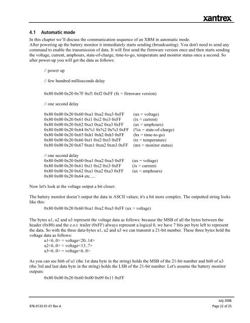
4.1 Automatic mode<br />
In this chapter we’ll discuss the communication sequence of an XBM in automatic mode.<br />
After powering up the battery monitor it immediately starts sending (broadcasting). You don't need to send any<br />
command to enable the transmission of data. It will first send the firmware version once and then starts sending<br />
the voltage, current, amphours, state-of-charge, time-to-go, temperature and monitor status once a second. So<br />
after power-up you will get the data as follows:<br />
// power up<br />
// few hundred milliseconds delay<br />
0x80 0x00 0x20 0x7F 0xf1 0xf2 0xFF (fx = firmware version)<br />
// one second delay<br />
0x80 0x00 0x20 0x60 0xu1 0xu2 0xu3 0xFF<br />
0x80 0x00 0x20 0x61 0xi1 0xi2 0xi3 0xFF<br />
0x80 0x00 0x20 0x62 0xa1 0xa2 0xa3 0xFF<br />
0x80 0x00 0x20 0x64 0x%1 0x%2 0x%3 0xFF<br />
0x80 0x00 0x20 0x65 0xh1 0xh2 0xh3 0xFF<br />
0x80 0x00 0x20 0x66 0xt1 0xt2 0xt3 0xFF<br />
0x80 0x00 0x20 0x67 0xm1 0xm2 0xm3 0xFF<br />
// one second delay<br />
0x80 0x00 0x20 0x60 0xu1 0xu2 0xu3 0xFF<br />
0x80 0x00 0x20 0x61 0xi1 0xi2 0xi3 0xFF<br />
0x80 0x00 0x20 0x62 0xa1 0xa2 0xa3 0xFF<br />
0x80 0x00 0x20 0x64 etc.....<br />
(ux = voltage)<br />
(ix = current)<br />
(ax = amphours)<br />
(%x = state-of-charge)<br />
(hx = time-to-go)<br />
(tx = temperature)<br />
(mx = monitor status)<br />
(ux = voltage)<br />
(ix = current)<br />
(ax = amphours)<br />
Now let's look at the voltage output a bit closer:<br />
The battery monitor doesn’t output the data in ASCII values; it's a bit more complex. The outputted string looks<br />
like this:<br />
0x80 0x00 0x20 0x60 0xu1 0xu2 0xu3 0xFF (ux = voltage)<br />
The bytes u1, u2 and u3 represent the voltage data as follows: because the MSB of all the bytes between the<br />
header (0x80) and the e.o.t. trailer (0xFF) always represent a logical 0, we have 7 bits per byte left to represent<br />
the data. So with the three data-bytes u1, u2 and u3 we can transmit a 21-bit number. These three bytes hold the<br />
voltage data as follows:<br />
u1 = voltage<br />
u2 = voltage<br />
u3 = voltage<br />
As you can see bit6 of u1 (the 1st data byte in the string) holds the MSB of the 21-bit number and bit0 of u3<br />
(the 3rd and last data byte in the string) holds the LSB of the 21-bit number. Let's assume the battery monitor<br />
outputs:<br />
0x80 0x00 0x20 0x60 0x00 0x09 0x11 0xFF<br />
July 2006<br />
976-0133-01-01 Rev A Page 22 of 25