Xantrex Battery Monitor Communication Interface Specifications
Xantrex Battery Monitor Communication Interface Specifications
Xantrex Battery Monitor Communication Interface Specifications

Create successful ePaper yourself
Turn your PDF publications into a flip-book with our unique Google optimized e-Paper software.
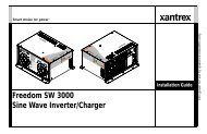
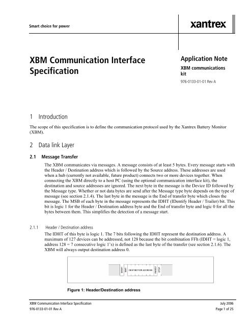
XBM <strong>Communication</strong> <strong>Interface</strong><br />
Specification<br />
Application Note<br />
XBM communications<br />
kit<br />
976-0133-01-01 Rev A<br />
1 Introduction<br />
The scope of this specification is to define the communication protocol used by the <strong>Xantrex</strong> <strong>Battery</strong> <strong>Monitor</strong><br />
(XBM).<br />
2 Data link Layer<br />
2.1 Message Transfer<br />
The XBM communicates via messages. A message consists of at least 5 bytes. Every message starts with<br />
the Header / Destination address which is followed by the Source address. These addresses are used<br />
when a hub (currently not available, future product) connects two or more devices together. When<br />
connecting the XBM directly to a host PC (using the optional communication interface kit), the<br />
destination and source addresses are ignored. The next byte in the message is the Device ID followed by<br />
the Message type. Whether or not data bytes are send after the Message type byte depends on the type of<br />
message (see section 2.1.4). The last byte in the message is the End of transfer byte which closes the<br />
message. The MSB of each byte in the message represents the IDHT (IDentify Header / Trailer) bit. This<br />
bit is logic 1 for the Header / Destination address byte and the End of transfer byte and logic 0 for all the<br />
bytes between them. This simplifies the detection of a message start.<br />
2.1.1 Header / Destination address<br />
The IDHT of this byte is logic 1. The 7 bits following the IDHT represent the destination address. A<br />
maximum of 127 devices can be addressed, not 128 because the bit combination FFh (IDHT = logic 1,<br />
address 128 = 7 consecutive logic 1’s) is defined as the last byte of the transfer (see section 2.1.6). The<br />
XBM will always output destination address 0.<br />
Figure 1: Header/Destination address<br />
XBM <strong>Communication</strong> <strong>Interface</strong> Specification July 2006<br />
976-0133-01-01 Rev A Page 1 of 25
2.1.2 Source Address<br />
The IDHT of this byte is logic 0. The 7 bits following the IDHT represent the address of the sender. The<br />
XBM will always output source address 0.<br />
Figure 2: Source Address<br />
2.1.3 Device ID<br />
The IDHT of this byte is logic 0. The 7 bits following the IDHT represent what type of equipment<br />
(TBS inverter, battery monitor etc.) is sending the message. Each type of TBS equipment has its unique<br />
identification number. The Device ID of the XBM is 20h.<br />
Figure 3: Device ID<br />
2.1.4 Message type<br />
The IDHT of this byte is logic 0. The 7 bits following the IDHT represent the message type and can be<br />
divided into five groups:<br />
1.) System common handshake (00h..0Fh).<br />
2.) System common commands (10h..1Fh). Messages common for all TBS products like<br />
‘Standby on’, ‘Standby off’, ‘Alarm relays on’, ‘Alarm relays off’ etc.<br />
3.) System exclusive commands (20h..3Fh). These are commands which are different for each<br />
type of equipment. For example, an inverter can use sys-ex command 20h for activating the<br />
ASB- / Economy-mode, while a battery monitor uses this command number for a display test.<br />
4.) System exclusive data requests (40h..5Fh). If a device requests specific data from another<br />
device (i.e. host PC requests history data from a battery monitor) it will send a sys-ex data<br />
request. This data is then transferred to the requesting device using the numbers 60h to 7Fh.<br />
5.) System exclusive data (60h..7Fh). These are messages that contain data, for example battery<br />
voltage, battery current or all the settings of the monitor. The data will be sent in data bytes<br />
following the message type.<br />
July 2006<br />
976-0133-01-01 Rev A Page 2 of 25
Figure 4 : Message type<br />
See section 2.2 for an overview of all the XBM message types.<br />
2.1.5 Data field<br />
The data field contains data like battery voltage, battery current etc. Only ‘Sys-ex data’ messages<br />
can contain one or more data bytes. The number of data-bytes in a ‘Sys-ex data’ message is<br />
theoretically not limited. However, because of hardware limitations of the XBM, the data field<br />
can have a maximum length of 27 bytes.<br />
Figure 5 : Data field (example with 3 databytes)<br />
2.1.6 End of transfer<br />
The IDHT and the 7 following bits of this byte are all logic 1. This End of transfer byte is unique<br />
because no other field in a message can represent FFh.<br />
Figure 6 : End of transfer<br />
July 2006<br />
976-0133-01-01 Rev A Page 3 of 25
2.2 Message type overview<br />
This section gives an overview of all the message types the XBM understands.<br />
2.2.1 System common handshake<br />
0x00 ACK – Positive acknowledge.<br />
Transmission repetition rate: on acknowledge<br />
Direction: output / input<br />
Data type: handshake<br />
0x01 NACK – Negative acknowledge.<br />
Transmission repetition rate: on negative acknowledge<br />
Direction: output / input<br />
Data type: handshake<br />
0x02 NACK + repeat request – Negative acknowledge and request to send data again.<br />
Transmission repetition rate: on communication error<br />
Direction: output<br />
Data type: handshake<br />
2.2.2 System common commands<br />
0x12 Alarm switch off – Switches off the alarm switch.<br />
Transmission repetition rate: -<br />
Direction: input<br />
Data type: command<br />
0x13 Alarm switch on – Switches on the alarm switch.<br />
Transmission repetition rate: -<br />
Direction: input<br />
Data type: command<br />
2.2.3 System exclusive commands<br />
0x20 Display test off – Disables display test.<br />
Transmission repetition rate: -<br />
Direction: input<br />
Data type: command<br />
0x21 Display test on – Enables display test.<br />
Transmission repetition rate: -<br />
Direction: input<br />
Data type: command<br />
0x22 Backlight off – Turns off the backlight (provided that backlight is not on due to a key<br />
press).<br />
Transmission repetition rate: -<br />
Direction: input<br />
Data type: command<br />
July 2006<br />
976-0133-01-01 Rev A Page 4 of 25
0x23 Backlight on – Turns on the backlight.<br />
Transmission repetition rate: -<br />
Direction: input<br />
Data type: command<br />
0x24 Calibration mode off – Turns off calibration mode.<br />
Transmission repetition rate: -<br />
Direction: input<br />
Data type: command<br />
0x25 Calibration mode on – Turns on calibration mode, do not use this command.<br />
Transmission repetition rate: -<br />
Direction: input<br />
Data type: command<br />
0x26 Request only mode off – Turns off request only mode. Now the XBM sends data every<br />
second (this is the default factory status). Only available on firmware versions 1.01 and newer!<br />
Transmission repetition rate: -<br />
Direction: input<br />
Data type: command<br />
0x27 Request only mode on – Turns on request only mode. Now the XBM only sends data on<br />
request (requested by a sys-ex data request command). Only available on firmware versions<br />
1.01 and newer!<br />
Transmission repetition rate: -<br />
Direction: input<br />
Data type: command<br />
0x28 Store functions – Store functions in EEPROM.<br />
Transmission repetition rate: -<br />
Direction: input<br />
Data type: command<br />
0x29 Store history – Store history in EEPROM.<br />
Transmission repetition rate: -<br />
Direction: input<br />
Data type: command<br />
0x2A Store calibration coefficients – Store calibration coefficients in EEPROM.<br />
Transmission repetition rate: -<br />
Direction: input<br />
Data type: command<br />
0x30 Reset factory settings – Restore factory settings.<br />
Transmission repetition rate: -<br />
Direction: input<br />
Data type: command<br />
July 2006<br />
976-0133-01-01 Rev A Page 5 of 25
0x31 Reset charge efficiency – Reset automatically calculated charge efficiency to 90.0%.<br />
Transmission repetition rate: -<br />
Direction: input<br />
Data type: command<br />
0x32 Clear history – Clear all history data except automatically calculated charge efficiency.<br />
Transmission repetition rate: -<br />
Direction: input<br />
Data type: command<br />
0x3C Up switch pressed – User has pressed the ‘Up-switch’.<br />
Transmission repetition rate: on up-switch press<br />
Direction: output<br />
Data type: command<br />
0x3D Setup switch pressed – User has pressed the ‘Setup-switch’.<br />
Transmission repetition rate: on setup-switch press<br />
Direction: output<br />
Data type: command<br />
0x3E Down switch pressed – User has pressed the ‘Down-switch’.<br />
Transmission repetition rate: on down-switch press<br />
Direction: output<br />
Data type: command<br />
2.2.4 System exclusive data requests<br />
0x40 Voltage request – Request for voltage data.<br />
Transmission repetition rate: -<br />
Direction: input<br />
Data type: command<br />
0x41 Current request – Request for current data.<br />
Transmission repetition rate: -<br />
Direction: input<br />
Data type: command<br />
0x42 Amphours request – Request for amphours data. Only available on firmware versions 1.01<br />
and up!<br />
Transmission repetition rate: -<br />
Direction: input<br />
Data type: command<br />
0x44 StateOfCharge request – Request for state-of-charge data. Only available on firmware<br />
versions 1.01 and newer!<br />
Transmission repetition rate: -<br />
Direction: input<br />
Data type: command<br />
July 2006<br />
976-0133-01-01 Rev A Page 6 of 25
0x45 TimeToGo request – Request for time-to-go data. Only available on firmware versions 1.01<br />
and newer!<br />
Transmission repetition rate: -<br />
Direction: input<br />
Data type: command<br />
0x46 Temperature request – Request for temperature data. Only available on firmware versions<br />
1.01 and newer!<br />
Transmission repetition rate: -<br />
Direction: input<br />
Data type: command<br />
0x47 <strong>Monitor</strong>Status request – Request for monitor status bits.<br />
Transmission repetition rate: -<br />
Direction: input<br />
Data type: command<br />
0x4F All parameters request – Request for all measured and calculated parameters. Only<br />
available on firmware versions 1.01 and newer!<br />
Transmission repetition rate: -<br />
Direction: input<br />
Data type: command<br />
0x50 ParameterSelect request – Request for selected parameter.<br />
Transmission repetition rate: -<br />
Direction: input<br />
Data type: command<br />
0x51 FunctionDump request – Request for function dump.<br />
Transmission repetition rate: -<br />
Direction: input<br />
Data type: command<br />
0x52 HistoryDump request – Request for history dump.<br />
Transmission repetition rate: -<br />
Direction: input<br />
Data type: command<br />
0x58 Calibration coefficients request – Request for all calibration coefficients.<br />
Transmission repetition rate: -<br />
Direction: input<br />
Data type: command<br />
0x5F FirmwareVersion request – Request for firmware version.<br />
Transmission repetition rate: -<br />
Direction: input<br />
Data type: command<br />
July 2006<br />
976-0133-01-01 Rev A Page 7 of 25
2.2.5 System exclusive data<br />
0x60 Voltage – <strong>Battery</strong> voltage.<br />
Transmission repetition rate: 1s / on request<br />
Direction: output<br />
Data Length: 3 bytes<br />
Resolution: 0.01V / bit gain, 0V offset<br />
Signed: no<br />
Data range: 0V – 655.35V<br />
Data type: measured<br />
Databyte1 : Voltage<br />
Databyte2 : Voltage<br />
Databyte3 : Voltage<br />
0x61 Current – <strong>Battery</strong> current.<br />
Transmission repetition rate: 1s / on request<br />
Direction: output<br />
Data Length: 3 bytes<br />
Resolution: 0.01A / bit gain, 0A offset<br />
Signed: yes<br />
Data range: 0A – 655.35A<br />
Data type: measured<br />
Databyte1: Sign (0 = positive current, 1 = negative current)<br />
Databyte1 : Current<br />
Databyte2 : Current<br />
Databyte3 : Current<br />
0x62 Amphours – Amount of amphours removed from the battery.<br />
Transmission repetition rate: 1s<br />
Direction: output<br />
Data Length: 3 bytes<br />
Resolution: 0.1Ah / bit gain, 0Ah offset<br />
Signed: yes<br />
Data range: 0Ah – 2000.0Ah<br />
Data type: calculated<br />
Databyte1 : Sign (0 = positive amphours, 1 = negative amphours)<br />
Databyte1 : Amphours<br />
Databyte2 : Amphours<br />
Databyte3 : Amphours<br />
0x64 StateOfCharge – State of charge of the battery in percent where 0% represents a fully<br />
discharged, and 100% a fully charged battery.<br />
Transmission repetition rate: 1s<br />
Direction: output<br />
Data Length: 3 bytes<br />
Resolution: 0.1% / bit gain, 0% offset<br />
Signed: no<br />
Data range: 0% – 100.0%<br />
Data type: calculated<br />
Databyte1 : StateOfCharge <br />
Databyte2 : StateOfCharge <br />
Databyte3 : StateOfCharge <br />
July 2006<br />
976-0133-01-01 Rev A Page 8 of 25
0x65 TimeToGo – Time to go until the battery needs to be charged.<br />
Transmission repetition rate: 1s<br />
Direction: output<br />
Data Length: 3 bytes<br />
Resolution: 1minute / bit gain, 0minutes offset, hhh:mm format<br />
Signed: no<br />
Data range: 0:00 – 240:00<br />
Data type: calculated<br />
Databyte1 : TimeToGo <br />
Databyte2 : TimeToGo <br />
Databyte3 : TimeToGo <br />
Only available on firmware versions 1.01 and up: TimeToGo contains an extra bit which<br />
represents a negative time-to-go. A negative time-to-go means that the time to go till the battery<br />
needs to be charged is infinite because the mean current is positive (battery is being charged).<br />
On the monitor this is displayed as four dashes: ----h.<br />
Databyte1: Negative TimeToGo<br />
0x66 Temperature – <strong>Battery</strong> temperature.<br />
Transmission repetition rate: 1s<br />
Direction: output<br />
Data Length: 3 bytes<br />
Resolution: 1 / 256°C / bit gain, 0°C offset<br />
Signed: no<br />
Data range: 0°C – 50.000°C<br />
Data type: measured<br />
Databyte1 : Temperature <br />
Databyte2 : Temperature <br />
Databyte3 : Temperature <br />
July 2006<br />
976-0133-01-01 Rev A Page 9 of 25
0x67 <strong>Monitor</strong>Status – Status of the battery monitor.<br />
Transmission repetition rate: 1s<br />
Direction: output<br />
Data Length: 3 bytes<br />
Resolution: ---<br />
Signed: ---<br />
Data range: ---<br />
Data type: status<br />
Databyte1 : reserved<br />
Databyte1 : reserved<br />
Databyte1 : ChargedVoltage – Voltage > ChargedVoltage level<br />
Databyte1 : ChargedCurrent – Current < ChargedCurrent level<br />
Databyte1 : reserved<br />
Databyte1 : reserved<br />
Databyte1 : AlarmTest – Alarmswitch triggered due to sys-com command<br />
‘Alarm switch on’<br />
Databyte2 : BacklightTest – Backlight switched on due to sys-ex command<br />
‘Backlight on’<br />
Databyte2 : DisplayTest – Display test switched on due to sys-ex command<br />
‘Display test on’<br />
Databyte2 : NoTemperatureSensor – No temperature sensor detected by battery monitor<br />
Databyte2 : SetupMode – <strong>Battery</strong> monitor is in setup-mode<br />
Databyte2 : HistoryMode – <strong>Battery</strong> monitor is in history mode<br />
Databyte2 : SuperLock – Super-lock is enabled<br />
Databyte2 : OverVoltage – Overvoltage alarm is triggered<br />
Databyte3 : UnderVoltage – Undervoltage alarm is triggered<br />
Databyte3 : <strong>Battery</strong>Low – The discharge floor is reached, battery needs to be charged<br />
Databyte3 : <strong>Battery</strong>Flat – <strong>Battery</strong> is fully discharged (0.0%)<br />
Databyte3 : <strong>Battery</strong>Full – <strong>Battery</strong> is fully charged (100.0%)<br />
Databyte3 : Charge<strong>Battery</strong> – <strong>Battery</strong> needs to be charged<br />
Databyte3 : <strong>Monitor</strong>OutOfSync – <strong>Monitor</strong> is not in sync with battery, charge battery<br />
Databyte3 : <strong>Monitor</strong>Reset – <strong>Monitor</strong> has been reset due to a power-loss<br />
0x70 ParameterSelect – The parameter displayed on the battery monitor.<br />
Transmission repetition rate: on request<br />
Direction: output / input<br />
Data Length: 2 bytes<br />
Resolution: ---<br />
Signed: no<br />
Data range: 0 - 6<br />
Data type: status<br />
Databyte1: ParameterSelect<br />
Databyte2: ParameterSelect<br />
July 2006<br />
976-0133-01-01 Rev A Page 10 of 25
0x71 FunctionDump – Dump of all the settings of the battery monitor.<br />
Transmission repetition rate: on request / on change<br />
Direction: output / input<br />
Data Length: 24 bytes<br />
Resolution: see format specification in section 2.2.6<br />
Signed: see format specification in section 2.2.6<br />
Data range: see format specification in section 2.2.6<br />
Data type: status<br />
0x72 HistoryDump – Dump of all the history events.<br />
Transmission repetition rate: on request<br />
Direction: output<br />
Data Length: 25 bytes<br />
Resolution: see format specification in section 2.2.7<br />
Signed: see format specification in section 2.2.7<br />
Data range: see format specification in section 2.2.7<br />
Data type: status<br />
0x78 CalibrationCoef1 – Used for voltage calibration, do not change this value.<br />
Transmission repetition rate: on request<br />
Direction: output / input<br />
Data Length: 3 bytes<br />
Resolution: ---<br />
Signed: no<br />
Data range: 0 – 65535<br />
Data type: calibrated<br />
Databyte1 : CalibrationCoef1<br />
Databyte2 : CalibrationCoef1<br />
Databyte3 : CalibrationCoef1<br />
0x79 CalibrationCoef2 – Used for current calibration, do not change this value.<br />
Transmission repetition rate: on request<br />
Direction: output / input<br />
Data Length: 3 bytes<br />
Resolution: ---<br />
Signed: no<br />
Data range: 0 – 65535<br />
Data type: calibrated<br />
Databyte1 : CalibrationCoef2<br />
Databyte2 : CalibrationCoef2<br />
Databyte3 : CalibrationCoef2<br />
July 2006<br />
976-0133-01-01 Rev A Page 11 of 25
0x7A CalibrationCoef3 – Used for current calibration, do not change this value.<br />
Transmission repetition rate: on request<br />
Direction: output / input<br />
Data Length: 3 bytes<br />
Resolution: ---<br />
Signed: no<br />
Data range: 0 – 65535<br />
Data type: calibrated<br />
Databyte1 : CalibrationCoef3<br />
Databyte2 : CalibrationCoef3<br />
Databyte3 : CalibrationCoef3<br />
0x7B CalibrationCoef4 – Used for current calibration, do not change this value.<br />
Transmission repetition rate: on request<br />
Direction: output / input<br />
Data Length: 3 bytes<br />
Resolution: ---<br />
Signed: no<br />
Data range: 0 – 65535<br />
Data type: calibrated<br />
Databyte1 : CalibrationCoef4<br />
Databyte2 : CalibrationCoef4<br />
Databyte3 : CalibrationCoef4<br />
0x7C CalibrationCoef5 – Used for temperature calibration, do not change this value.<br />
Transmission repetition rate: on request<br />
Direction: output / input<br />
Data Length: 3 bytes<br />
Resolution: ---<br />
Signed: no<br />
Data range: 0 – 65535<br />
Data type: calibrated<br />
Databyte1 : CalibrationCoef5<br />
Databyte2 : CalibrationCoef5<br />
Databyte3 : CalibrationCoef5<br />
0x7D CalibrationCoef6 – Used for temperature calibration, do not change this value.<br />
Transmission repetition rate: on request<br />
Direction: output / input<br />
Data Length: 3 bytes<br />
Resolution: ---<br />
Signed: no<br />
Data range: 0 – 65535<br />
Data type: calibrated<br />
Databyte1 : CalibrationCoef6<br />
Databyte2 : CalibrationCoef6<br />
Databyte3 : CalibrationCoef6<br />
July 2006<br />
976-0133-01-01 Rev A Page 12 of 25
0x7F FirmwareVersion – Firmware version of the battery monitor.<br />
Transmission repetition rate: on request<br />
Direction: output / input<br />
Data Length: 2 bytes<br />
Resolution: 0.01 / bit gain, 0 offset<br />
Signed: no<br />
Data range: 1.00 – 163.84<br />
Data type: status<br />
Databyte1 : FirmwareVersion<br />
Databyte2 : FirmwareVersion<br />
2.2.6 FunctionDump format specification<br />
The data field in a function-dump is a chunk of 24 bytes containing all the functions (settings) of<br />
the XBM. This data needs some additional processing to actually represent the XBM settings.<br />
Some functions need an offset while others must be multiplied by a constant or variable factor.<br />
F01 <strong>Battery</strong> capacity – <strong>Battery</strong> capacity (Ah).<br />
Direction: output / input<br />
Data Length: 2 bytes<br />
Resolution: 1Ah / bit gain, 20Ah offset<br />
Signed: no<br />
Data range: 20 – 2000Ah<br />
Data type: status<br />
Databyte1 : Function1<br />
Databyte2 : Function1<br />
F01 = ((Databyte1 * 0x80) + Databyte2) + 20<br />
F02 Charged Voltage – Voltage charged parameter (V).<br />
Direction: output / input<br />
Data Length: 1 byte<br />
Resolution: 0.1V / bit gain, 8.0V offset<br />
Signed: no<br />
Data range: 8.0 – 33.0V<br />
Data type: status<br />
Databyte3 : Function2<br />
Databyte4 : Function2<br />
F02 = (((Databyte3 * 0x80) + Databyte4) * F16 * 0.1) + 8.0<br />
F03 Charged Current – Current charged parameter (% of bat.cap.).<br />
Direction: output / input<br />
Data Length: 1 byte<br />
Resolution: 0.5% / bit gain, 0.5% offset<br />
Signed: no<br />
Data range: 0.5 – 10.0%<br />
Data type: status<br />
Databyte5 : Function3<br />
F03 = (Databyte5 + 1) * 0.5<br />
July 2006<br />
976-0133-01-01 Rev A Page 13 of 25
F04 Charged Time – Charged parameter time (minutes).<br />
Direction: output / input<br />
Data Length: 1 byte<br />
Resolution: 1m / bit gain, 1m offset<br />
Signed: no<br />
Data range: 1 – 4m<br />
Data type: status<br />
Databyte6 : Function4<br />
F04 = Databyte6 + 1<br />
F05 Low <strong>Battery</strong> On – Low <strong>Battery</strong> alarm on / discharge floor (%).<br />
Direction: output / input<br />
Data Length: 1 byte<br />
Resolution: 1% / bit gain, 0% offset<br />
Signed: no<br />
Data range: 0 – 99%<br />
Data type: status<br />
Databyte7 : Function5<br />
F05 = Databyte7<br />
F06 Low <strong>Battery</strong> Off – Low <strong>Battery</strong> alarm off (%).<br />
Direction: output / input<br />
Data Length: 1 byte<br />
Resolution: 1% / bit gain, 1% offset<br />
Signed: no<br />
Data range: 1 – 100% / FULL<br />
Data type: status<br />
Databyte8 : Function6<br />
if Databyte8 = 100<br />
then F06 = ‘FULL’<br />
else F06 = Databyte8 + 1<br />
F07 UnderVoltage Alarm – Under-voltage alarm (V).<br />
Direction: output / input<br />
Data Length: 2 bytes<br />
Resolution: 0.1V / bit gain, 7.9V offset<br />
Signed: no<br />
Data range: OFF / 8.0 – 33.0V<br />
Data type: status<br />
Databyte9 : Function7<br />
Databyte10 : Function7<br />
if ((Databyte9 * 0x80) + Databyte10) = 0<br />
then F07 = ‘OFF’<br />
else F07 = (((Databyte9 * 0x80) + Databyte10)-1 * F16 * 0.1) + 8.0<br />
July 2006<br />
976-0133-01-01 Rev A Page 14 of 25
F08 OverVoltage Alarm – Over-voltage alarm (V).<br />
Direction: output / input<br />
Data Length: 2 bytes<br />
Signed: no<br />
Resolution: 0.1V / bit gain, 9.9V offset<br />
Data range: OFF / 10.0 – 35.0V<br />
Data type: status<br />
Databyte11 : Function8<br />
Databyte12 : Function8<br />
if ((Databyte11 * 0x80) + Databyte12) = 0<br />
then F08 = ‘OFF’<br />
else F08 = (((Databyte11 * 0x80) + Databyte12) * F16 * 0.1) + 10.0<br />
F09 Charge Efficiency – Charge efficiency factor / CEF (%).<br />
Direction: output / input<br />
Data Length: 1 byte<br />
Resolution: 1% / bit gain, 50% offset<br />
Signed: no<br />
Data range: 50 – 99% / AU / A90<br />
Data type: status<br />
Databyte13 : Function9<br />
If Databyte13 = 50<br />
then F09 = ‘AU’<br />
else if Databyte13 = 51<br />
then F09 = ‘A90’<br />
else F09 = Databyte13 + 50<br />
F10 Peukert Exponent – Peukert exponent.<br />
Direction: output / input<br />
Data Length: 1 byte<br />
Resolution: 0.01 / bit gain, 1.00 offset<br />
Signed: no<br />
Data range: 1.00 – 1.50<br />
Data type: status<br />
Databyte14 : Function10<br />
F10 = Databyte14 + 1.00<br />
F11 <strong>Battery</strong> Temperature – <strong>Battery</strong> temperature (°C).<br />
Direction: output / input<br />
Data Length: 1 byte<br />
Resolution: 1°C / bit gain, 0°C offset<br />
Signed: no<br />
Data range: 0 – 50°C / AU<br />
Data type: status<br />
Databyte15 : Function11<br />
if Databyte15 = 51<br />
then F11 = ‘AU’<br />
else F11 = Databyte15<br />
July 2006<br />
976-0133-01-01 Rev A Page 15 of 25
F12 Temperature Coefficient– <strong>Battery</strong> temperature coefficient (%cap/°C).<br />
Direction: output / input<br />
Data Length: 1 byte<br />
Resolution : 0.05%cap/°C / bit gain, 0.00%cap/°C offset<br />
Signed: no<br />
Data range: OFF / 0.05 – 0.95%cap/°C<br />
Data type: status<br />
Databyte16 : Function12<br />
if DataByte16 = 0<br />
then F12 = ‘OFF’<br />
else F12 = DataByte16 * 0.05<br />
F13 TimeToGo Averaging Period – Time-to-go averaging period (minutes).<br />
Direction: output / input<br />
Data Length: 1 byte<br />
Resolution: 3m / bit gain, 0m offset<br />
Signed: no<br />
Data range: 0 – 12m<br />
Data type: status<br />
Databyte17 : Function13<br />
F13 = DataByte17 * 3<br />
F14 Current Threshold – Current threshold (A).<br />
Direction: output / input<br />
Data Length: 1 byte<br />
Resolution: 0.1A / bit gain, 0.0A offset<br />
Signed: no<br />
Data range: 0.0 – 2.0A<br />
Data type: status<br />
Databyte18 : Function14<br />
F14 = DataByte18 * 0.1<br />
F15 Temperature Unit Selection – Temperature unit selection. Only available on firmware<br />
versions<br />
1.10 and newer!<br />
Direction: output / input<br />
Data Length: 1 byte<br />
Resolution: ---<br />
Signed: no<br />
Data range: °C / °F<br />
Data type: status<br />
Databyte19 : Function15<br />
if DataByte19<br />
then F15 = ‘°C’<br />
else F15 = ‘°F’<br />
July 2006<br />
976-0133-01-01 Rev A Page 16 of 25
F16 Voltage Prescaler – Voltage prescaler.<br />
Direction: output / input<br />
Data Length: 1 byte<br />
Resolution: ---<br />
Signed: no<br />
Data range: 1:1 / 1:5 / 1:10<br />
Data type: status<br />
Databyte20 : Function16<br />
if DataByte20 = 0<br />
then F16 = 1<br />
else if DataByte20 = 1<br />
then F16 = 5<br />
else F16 = 10<br />
F17 Display Mode – Display backlight mode (s).<br />
Direction: output / input<br />
Data Length: 1 byte<br />
Resolution: 10s / bit gain, 0s offset<br />
Signed: no<br />
Data range: OFF / 10 – 60 / ON / AU<br />
Data type: status<br />
Databyte21 : Function17<br />
if DataByte21 = 0<br />
then F17 = ‘OFF’<br />
else if DataByte21 = 7<br />
then F17 = ‘ON’<br />
else if DataByte21 = 8<br />
then F17 = ‘AU’<br />
else F17 = DataByte21 * 10<br />
F18 Alarm Contact Polarity – Alarm contact polarity. Only available on firmware versions 1.01<br />
and newer!<br />
Direction: output / input<br />
Data Length: 1 byte<br />
Resolution: ---<br />
Signed: no<br />
Data range: NO / NC<br />
Data type: status<br />
Databyte22 : Function18<br />
if DataByte22 = 0<br />
then F18 = ‘NO’<br />
else F18 = ‘NC’<br />
July 2006<br />
976-0133-01-01 Rev A Page 17 of 25
F19 Display Parameter – Display parameter.<br />
This is a special (sort of hidden) function. On the XBM itself, reading out F19 will give you the<br />
battery monitor’s firmware version. Since the firmware version can be retrieved thru its own<br />
message via TBS-Link, the necessity of retrieving it via the function dump becomes obsolete.<br />
Therefore F19 is used to enable / disable the readout of each individual parameter in normal<br />
operation of the XBM. When a parameter readout is enabled, its corresponding bit in Databyte23<br />
is set otherwise it is cleared. Note that this function only affects the readout on the XBM itself, a<br />
disabled parameter can always be retrieved via TBS-Link.<br />
Direction: output / input<br />
Data Length: 1 byte<br />
Resolution: ---<br />
Signed: no<br />
Data range: ---<br />
Data type: status<br />
Databyte23: Enable / disable Voltage readout<br />
Databyte23: Enable / disable Current readout<br />
Databyte23: Enable / disable Amphours readout<br />
Databyte23: Enable / disable StateOfCharge readout<br />
Databyte23: Enable / disable TimeToGo readout<br />
Databyte23: Enable / disable Temperature readout<br />
F19 = DataByte23<br />
F20 Setup Lock – Setup lock.<br />
Direction: output / input<br />
Data Length: 1 byte<br />
Resolution: ---<br />
Signed: no<br />
Data range: OFF / ON<br />
Data type: status<br />
Databyte24 : Function20<br />
if DataByte24 = 0<br />
then F20 = ‘OFF’<br />
else F20 = ‘ON’<br />
2.2.7 HistoryDump format specification<br />
The data field in a history-dump is a chunk of 25 bytes containing all the history data of the<br />
XBM.<br />
H01 Charge Efficiency – Automatically calculated Charge Efficiency Factor (%).<br />
Direction: output<br />
Data Length: 3 bytes<br />
Resolution: 0.1 / 65536 % / bit gain, 0.0% offset<br />
Signed: no<br />
Data range: 0.0 – 100.0%<br />
Data type: calculated<br />
Databyte1 : History1<br />
Databyte2 : History1<br />
Databyte3 : History1<br />
July 2006<br />
976-0133-01-01 Rev A Page 18 of 25
H02 Average Discharge (Ah) – Average discharge in Amphours (Ah).<br />
Direction: output<br />
Data Length: 3 bytes<br />
Resolution: 0.1Ah / bit gain, 0.0Ah offset<br />
Signed: yes (always negative)<br />
Data range: 0Ah – 1999.9Ah<br />
Data type: calculated<br />
Databyte4 : History2<br />
Databyte5 : History2<br />
Databyte6 : History2<br />
H03 Deepest Discharge (Ah) – Deepest discharge in Amphours (Ah).<br />
Direction: output<br />
Data Length: 3 bytes<br />
Resolution: 0.1Ah / bit gain, 0.0Ah offset<br />
Signed: yes (always negative)<br />
Data range: 0Ah – 1999.9Ah<br />
Data type: calculated<br />
Databyte7 : History3<br />
Databyte8 : History3<br />
Databyte9 : History3<br />
H04 Charge Discharge Cycles – Number of charge-discharge cycles (#).<br />
Direction: output<br />
Data Length: 2 bytes<br />
Resolution: 1 / bit gain, 0 offset<br />
Signed: no<br />
Data range: 0 – 9999<br />
Data type: calculated<br />
Databyte10 : History4<br />
Databyte11 : History4<br />
H05 Synchronizations – Number of synchronizations (#).<br />
Direction: output<br />
Data Length: 2 bytes<br />
Resolution: 1 / bit gain, 0 offset<br />
Signed: no<br />
Data range: 0 – 9999<br />
Data type: calculated<br />
Databyte12 : History5<br />
Databyte13 : History5<br />
H06 Full Discharges – Number of full discharges (#).<br />
Direction: output<br />
Data Length: 2 bytes<br />
Resolution: 1 / bit gain, 0 offset<br />
Signed: no<br />
Data range: 0 – 9999<br />
Data type: calculated<br />
Databyte14 : History6<br />
Databyte15 : History6<br />
July 2006<br />
976-0133-01-01 Rev A Page 19 of 25
H07 UnderVoltage triggers – Number of under-voltage triggers (#).<br />
Direction: output<br />
Data Length: 2 bytes<br />
Resolution: 1 / bit gain, 0 offset<br />
Signed: no<br />
Data range: 0 – 9999<br />
Data type: calculated<br />
Databyte16 : History7<br />
Databyte17 : History7<br />
H08 OverVoltage triggers – Number of over-voltage triggers (#).<br />
Direction: output<br />
Data Length: 2 bytes<br />
Resolution: 1 / bit gain, 0 offset<br />
Signed: no<br />
Data range: 0 – 9999<br />
Data type: calculated<br />
Databyte18 : History8<br />
Databyte19 : History8<br />
H09 Average Discharge (%) – Average discharge in percent state-of-charge (%).Only available<br />
on firmware versions 1.03 and newer!<br />
Direction: output<br />
Data Length: 3 bytes<br />
Resolution: 0.1% / bit gain, 0.0% offset<br />
Signed: yes (always negative)<br />
Data range: 0.0 – 100.0%<br />
Data type: calculated<br />
Databyte20 : History9<br />
Databyte21 : History9<br />
Databyte22 : History9<br />
H10 Deepest Discharge (%) – Deepest discharge in percent state-of-charge (%). Only available<br />
on firmware versions 1.03 and newer!<br />
Direction: output<br />
Data Length: 3 bytes<br />
Resolution: 0.1% / bit gain, 0.0% offset<br />
Signed: yes (always negative)<br />
Data range: 0.0 – 100.0%<br />
Data type: calculated<br />
Databyte23 : History10<br />
Databyte24 : History10<br />
Databyte25 : History10<br />
July 2006<br />
976-0133-01-01 Rev A Page 20 of 25
3 PHYSICAL LAYER<br />
The XBM outputs its data a-synchronously at 2400bps using 8 data bits, 1 stop bit and even parity. Pin 2<br />
and 3 of the expansion port are TTL-level receive and transmit ports of the battery monitor. Use the<br />
optionally available isolated RS-232 interface to transform these TTL-levels to RS-232 levels. The input<br />
to output isolation barrier of this interface is >1000V, so the battery monitor can be safely connected to<br />
every PC or notebook. Note that the isolated RS-232 interface draws a current of 16 to 30mA from your<br />
battery.<br />
The pin out of the rear side RJ12 expansion port is as follows:<br />
4 PRACTICAL EXAMPLES<br />
The XBM can operate in one of two communication modes.<br />
Automatic mode: the battery monitor outputs all measured and calculated parameters automatically once<br />
second and transmits data when pressing a key and when leaving setup mode. This is the standard mode<br />
for every XBM leaving the factory.<br />
Request only mode: the battery monitor only sends data when receiving a request for it (through a<br />
sys-ex data request, see chapter 2.2.4). Transmitting data when pressing a key and when leaving setupmode<br />
is also disabled this mode.<br />
Regardless of the selected communication mode, the monitor will send the firmware version on power<br />
up. This is necessary for compatibility with the XBM monitoring software.<br />
Note: The request only mode is only available on firmware versions 1.01 and newer. Therefore only chapter<br />
4.1 is of interest for users communicating with an XBM containing firmware version 1.00.<br />
Note : It is possible that, when in request only mode and the supplyvoltage of the monitor (and the<br />
communication interface) is decreasing slowly to a level outside the RS-232 margins, the monitor<br />
sends a NACK+Repeat Request due to a communication error.<br />
July 2006<br />
976-0133-01-01 Rev A Page 21 of 25
4.1 Automatic mode<br />
In this chapter we’ll discuss the communication sequence of an XBM in automatic mode.<br />
After powering up the battery monitor it immediately starts sending (broadcasting). You don't need to send any<br />
command to enable the transmission of data. It will first send the firmware version once and then starts sending<br />
the voltage, current, amphours, state-of-charge, time-to-go, temperature and monitor status once a second. So<br />
after power-up you will get the data as follows:<br />
// power up<br />
// few hundred milliseconds delay<br />
0x80 0x00 0x20 0x7F 0xf1 0xf2 0xFF (fx = firmware version)<br />
// one second delay<br />
0x80 0x00 0x20 0x60 0xu1 0xu2 0xu3 0xFF<br />
0x80 0x00 0x20 0x61 0xi1 0xi2 0xi3 0xFF<br />
0x80 0x00 0x20 0x62 0xa1 0xa2 0xa3 0xFF<br />
0x80 0x00 0x20 0x64 0x%1 0x%2 0x%3 0xFF<br />
0x80 0x00 0x20 0x65 0xh1 0xh2 0xh3 0xFF<br />
0x80 0x00 0x20 0x66 0xt1 0xt2 0xt3 0xFF<br />
0x80 0x00 0x20 0x67 0xm1 0xm2 0xm3 0xFF<br />
// one second delay<br />
0x80 0x00 0x20 0x60 0xu1 0xu2 0xu3 0xFF<br />
0x80 0x00 0x20 0x61 0xi1 0xi2 0xi3 0xFF<br />
0x80 0x00 0x20 0x62 0xa1 0xa2 0xa3 0xFF<br />
0x80 0x00 0x20 0x64 etc.....<br />
(ux = voltage)<br />
(ix = current)<br />
(ax = amphours)<br />
(%x = state-of-charge)<br />
(hx = time-to-go)<br />
(tx = temperature)<br />
(mx = monitor status)<br />
(ux = voltage)<br />
(ix = current)<br />
(ax = amphours)<br />
Now let's look at the voltage output a bit closer:<br />
The battery monitor doesn’t output the data in ASCII values; it's a bit more complex. The outputted string looks<br />
like this:<br />
0x80 0x00 0x20 0x60 0xu1 0xu2 0xu3 0xFF (ux = voltage)<br />
The bytes u1, u2 and u3 represent the voltage data as follows: because the MSB of all the bytes between the<br />
header (0x80) and the e.o.t. trailer (0xFF) always represent a logical 0, we have 7 bits per byte left to represent<br />
the data. So with the three data-bytes u1, u2 and u3 we can transmit a 21-bit number. These three bytes hold the<br />
voltage data as follows:<br />
u1 = voltage<br />
u2 = voltage<br />
u3 = voltage<br />
As you can see bit6 of u1 (the 1st data byte in the string) holds the MSB of the 21-bit number and bit0 of u3<br />
(the 3rd and last data byte in the string) holds the LSB of the 21-bit number. Let's assume the battery monitor<br />
outputs:<br />
0x80 0x00 0x20 0x60 0x00 0x09 0x11 0xFF<br />
July 2006<br />
976-0133-01-01 Rev A Page 22 of 25
This would represent a voltage of:<br />
(0x00
The format of the state-of-charge output is basically the same as that of the voltage output only that the state-ofcharge<br />
output is hardware limited to 0x3E8 = 1000d which represents 100.0%.<br />
When we take a closer look at the time-to-go format in chapter 2.2.5, we see that this is in a hhh:mm format<br />
when we look at it decimally. This means that the two least significant decimal digits represent the number of<br />
minutes left and the rest of the decimal digits represent the number hours left.<br />
If for example the monitor outputs :<br />
0x80 0x00 0x20 0x65 0x00 0x0B 0x2C 0xFF<br />
then shifting 0x0B left 7 positions and adding 0x2C would make 0x5AC which decimally represents 1452d<br />
(or 01452d). This number represents 14 hours and 52 minutes to go. The range is 0:00 to 240:00. So 24000d<br />
represents 240 hours and 0 minutes.<br />
Here's a C coded example of getting the hours and minutes (where d1, d2, and d3 are the three received data<br />
bytes):<br />
unsigned int TimeToGo, Hours, Minutes;<br />
TimeToGo = (d1
<strong>Xantrex</strong> is a registered trademark of <strong>Xantrex</strong> International.<br />
© 2003 <strong>Xantrex</strong> International. All rights reserved.<br />
Technical Bulletin: © July 2006 <strong>Xantrex</strong> International<br />
UNLESS SPECIFICALLY AGREED TO IN WRITING, XANTREX TECHNOLOGY INC. (“XANTREX”):<br />
(a) MAKES NO WARRANTY AS TO THE ACCURACY, SUFFICIENCY OR SUITABILITY OF ANY TECHNICAL OR OTHER INFORMATION PROVIDED IN ITS MANUALS OR<br />
OTHER DOCUMENTATION.<br />
(b) ASSUMES NO RESPONSIBILITY OR LIABILITY FOR LOSS OR DAMAGE, WHETHER DIRECT, INDIRECT, CONSEQUENTIAL OR INCIDENTAL, WHICH MIGHT ARISE<br />
OUT OF THE USE OF SUCH INFORMATION. THE USE OF ANY SUCH INFORMATION WILL BE ENTIRELY AT THE USER’S RISK.<br />
Part number: 976-0133-01-01 Rev A<br />
Contact information:<br />
Phone:<br />
1-800-670-0707 (toll-free in North America)<br />
Phone:<br />
1-360-925-5097 (outside North America)<br />
Fax: 1-360-925-5143<br />
Email:<br />
customerservice@xantrex.com<br />
Web:<br />
www.xantrex.com<br />
July 2006<br />
976-0133-01-01 Rev A Page 25 of 25