PROsine 2.5 and 3.0 - Xantrex
PROsine 2.5 and 3.0 - Xantrex
PROsine 2.5 and 3.0 - Xantrex

You also want an ePaper? Increase the reach of your titles
YUMPU automatically turns print PDFs into web optimized ePapers that Google loves.
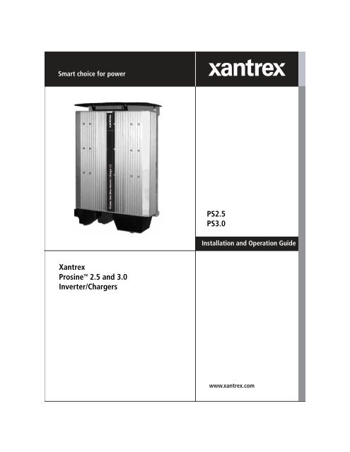
PS<strong>2.5</strong><br />
PS<strong>3.0</strong><br />
Installation <strong>and</strong> Operation Guide<br />
<strong>Xantrex</strong><br />
Prosine TM <strong>2.5</strong> <strong>and</strong> <strong>3.0</strong><br />
Inverter/Chargers
TM<br />
Prosine<br />
PS<strong>2.5</strong> Inverter/Charger<br />
PS<strong>3.0</strong> Inverter/Charger<br />
Installation <strong>and</strong> Operation Guide
About <strong>Xantrex</strong><br />
<strong>Xantrex</strong> Technology Inc. is a world-leading supplier of advanced power electronics <strong>and</strong> controls with products from<br />
50 watt mobile units to one MW utility-scale systems for wind, solar, batteries, fuel cells, microturbines, <strong>and</strong> backup<br />
power applications in both grid-connected <strong>and</strong> st<strong>and</strong>alone systems. <strong>Xantrex</strong> products include inverters, battery<br />
chargers, programmable power supplies, <strong>and</strong> variable speed drives that convert, supply, control, clean, <strong>and</strong> distribute<br />
electrical power.<br />
Trademarks<br />
<strong>Xantrex</strong> is a registered trademark of <strong>Xantrex</strong> International. © 2005 <strong>Xantrex</strong> International. All rights reserved. Prosine<br />
is a registered trademark of <strong>Xantrex</strong> International.<br />
Other trademarks, registered trademarks, <strong>and</strong> product names are the property of their respective owners <strong>and</strong> are used<br />
herein for identification purposes only.<br />
Notice of Copyright<br />
Installation <strong>and</strong> Operation Guide © June 2005 <strong>Xantrex</strong> International.<br />
Disclaimer<br />
<strong>Xantrex</strong> manufactures its products from parts <strong>and</strong> components that are new or equivalent to new, in accordance with<br />
industry-st<strong>and</strong>ard practices.<br />
UNLESS SPECIFICALLY AGREED TO IN WRITING, XANTREX TECHNOLOGY INC. (“XANTREX”):<br />
(a) MAKES NO WARRANTY AS TO THE ACCURACY, SUFFICIENCY OR SUITABILITY OF ANY TECHNICAL OR<br />
OTHER INFORMATION PROVIDED IN ITS MANUALS OR OTHER DOCUMENTATION.<br />
(b) ASSUMES NO RESPONSIBILITY OR LIABILITY FOR LOSS OR DAMAGE, WHETHER DIRECT, INDIRECT,<br />
CONSEQUENTIAL OR INCIDENTAL, WHICH MIGHT ARISE OUT OF THE USE OF SUCH INFORMATION. THE USE<br />
OF ANY SUCH INFORMATION WILL BE ENTIRELY AT THE USER’S RISK.<br />
Date <strong>and</strong> Revision<br />
June 2005, Revision A<br />
Part number<br />
445-0096-01-01<br />
Contact information<br />
Telephone: 1-800-670-0707 (toll free in North America)<br />
1-360-925-5097 (outside North America)<br />
Fax: 1-360-925-5143 (outside North America)<br />
Email: customerservice@xantrex.com<br />
Web: www.xantrex.com
IMPORTANT SAFETY INSTRUCTIONS<br />
This manual contains important safety <strong>and</strong> operating instructions as prescribed by UL <strong>and</strong> CSA<br />
specifications for inverter/chargers. This manual covers PS <strong>2.5</strong> <strong>and</strong> PS <strong>3.0</strong>, 12- <strong>and</strong> 24-volt model<br />
inverter/chargers.<br />
General Safety Precautions<br />
1. READ AND SAVE THESE INSTRUCTIONS. They contain important<br />
safety <strong>and</strong> operating information for the Prosine inverter/charger.<br />
2. Before using the inverter/charger, read all instructions <strong>and</strong> cautionary markings<br />
on (1) the inverter/charger, (2) the batteries, <strong>and</strong> (3) all appropriate sections of<br />
this instruction manual.<br />
3. Do not expose the Prosine inverter/charger to rain, snow, spray or bilge water.<br />
To reduce risk of fire hazard, do not cover or obstruct the ventilation openings.<br />
Do not install the Prosine inverter/charger in a zero-clearance compartment.<br />
Overheating may result.<br />
4. Do not use attachments not recommended or sold by the manufacturer. Doing<br />
so may result in a risk of fire, electric shock, or injury to persons.<br />
5. The Prosine inverter/charger is designed to be permanently connected to your<br />
AC <strong>and</strong> DC electrical systems. <strong>Xantrex</strong> recommends that all wiring be done by<br />
a certified technician or electrician to ensure adherence to proper electrical<br />
wiring regulations.<br />
6. To avoid a risk of fire <strong>and</strong> electric shock, make sure that existing wiring is in<br />
good electrical condition; <strong>and</strong> that wire size is not undersized. Do not operate<br />
the Prosine inverter/charger with damaged or subst<strong>and</strong>ard wiring.<br />
7. Do not operate the Prosine inverter/charger if it has received a sharp blow,<br />
been dropped, or otherwise damaged in any way. If the Prosine inverter/<br />
charger is damaged, see the Warranty section of this manual.<br />
8. Do not disassemble the Prosine inverter/charger. See the Service section of the<br />
Owner’s Manual for instructions on obtaining service for the Prosine inverter/<br />
charger. Attempting to service the unit yourself may result in a risk of electrical<br />
shock or fire. Internal capacitors remain charged long after all power is disconnected.<br />
9. To reduce risk of electrical shock, disconnect both AC <strong>and</strong> DC power from the<br />
Prosine inverter/charger before attempting any maintenance or cleaning or<br />
working on any circuits connected to the Prosine inverter/charger. Turning off<br />
controls will not reduce this risk.<br />
10. Grounding: the Prosine inverter/charger must be provided with an equipmentgrounding<br />
conductor connected to the AC input ground terminal. Grounding<br />
<strong>and</strong> all other wiring must comply with local codes <strong>and</strong> ordinances<br />
11. For marine applications in the United States, external connections to the Prosine<br />
inverter/charger shall comply with the United States Coast Guard Electrical<br />
Regulations (33CFR183, Sub part 1).<br />
Prosine <strong>2.5</strong>/<strong>3.0</strong> Installation & Operation Guide<br />
i
12. WARNING—RISK OF EXPLOSIVE GASES<br />
a) WORKING IN THE VICINITY OF A LEAD-ACID BATTERY IS DAN-<br />
GEROUS. BATTERIES GENERATE EXPLOSIVE GASES DURING<br />
NORMAL BATTERY OPERATION. BEFORE INSTALLING OR<br />
USING YOUR INVERTER/CHARGER, READ THIS MANUAL AND<br />
FOLLOW THE INSTRUCTIONS EXACTLY.<br />
b) This equipment contains components which tend to produce arcs or sparks.<br />
To prevent fire or explosion do not install in compartments containing batteries<br />
or flammable materials or in locations which require ignition protected<br />
equipment. This includes any space containing gasoline-powered<br />
machinery, fuel tanks, or joints, fittings, or other connection between components<br />
of the fuel system.<br />
c) To reduce the risk of battery explosion, follow these instructions <strong>and</strong> those<br />
published by the battery manufacturer <strong>and</strong> the manufacturer of the equipment<br />
in which the battery is installed.<br />
13. PRECAUTIONS WHEN WORKING WITH BATTERIES<br />
a) Someone should be within range of your voice or close enough to come to<br />
your aid when you work near a lead-acid battery.<br />
b) Have plenty of fresh water <strong>and</strong> soap nearby in case battery acid contacts<br />
skin, clothing, or eyes.<br />
c) Wear complete eye protection <strong>and</strong> clothing protection. Avoid touching eyes<br />
while working near battery.<br />
d) If battery acid contacts skin or clothing, wash immediately with soap <strong>and</strong><br />
water. If acid enters eye, immediately flood eye with running cold water for<br />
at least 20 minutes <strong>and</strong> get medical attention immediately.<br />
e) Baking soda neutralizes lead-acid battery electrolyte. Keep a supply on<br />
h<strong>and</strong> in the area of the batteries.<br />
f) NEVER smoke or allow a spark or flame in vicinity of a battery or engine.<br />
g) Be extra cautious to reduce risk of dropping a metal tool on the battery. It<br />
might spark or short-circuit the battery or other electrical part that may<br />
cause an explosion.<br />
h) Remove personal metal items such as rings, bracelets, necklaces, <strong>and</strong><br />
watches when working with a lead-acid battery. A lead-acid battery produces<br />
a short-circuit current high enough to weld a ring or the like to metal,<br />
causing a severe burn.<br />
i) Use the Prosine inverter/charger for charging a LEAD-ACID battery only.<br />
Do not use the Prosine inverter/charger to charge nickel-cadmium or drycell<br />
batteries commonly used with home appliances <strong>and</strong> electronic equipment.<br />
These batteries may burst <strong>and</strong> cause injury to persons <strong>and</strong> damage to<br />
property.<br />
j) NEVER attempt to charge a frozen battery. Charging a battery when its<br />
temperature is below 32° F (0° C) is inefficient <strong>and</strong> ineffective. If possible,<br />
gradually warm the battery above 32° F (0° C) before charging.<br />
ii<br />
Prosine <strong>2.5</strong>/<strong>3.0</strong> Installation & Operation Guide
Materials List<br />
Materials List<br />
Your Prosine Inverter/Charger package includes the following items. (See the illustration on<br />
page v.)<br />
1. Prosine inverter/charger<br />
2. Control panel with fasteners<br />
3. Control panel communications cable<br />
4. Red & black DC terminal covers<br />
5. Installation <strong>and</strong> Operation Guide<br />
6. Quick Installation Guide<br />
7. Mounting brackets with fasteners (PS<strong>3.0</strong> only).<br />
8. Drip cover/vent shield<br />
9. Battery temperature sensor<br />
If any of these materials are missing from your package, or if it is unsatisfactory in any manner,<br />
please call Customer Service:<br />
Phone: 1-800-670-0707 (toll free) 1-360-925-5097 (direct)<br />
Fax: 1-360-925-5143<br />
Web site: http://www.xantrex.com<br />
Email: customerservice@xantrex.com<br />
Please record the following information:<br />
Model Number: _____________________________________<br />
Serial Number: _____________________________________<br />
Purchased From: ____________________________________<br />
Purchase Date: _____________________________________<br />
Comments:<br />
____________________________________________________________________________<br />
____________________________________________________________________________<br />
____________________________________________________________________________<br />
____________________________________________________________________________<br />
____________________________________________________________________________<br />
Thank you for choosing <strong>Xantrex</strong> to meet your independent power needs.<br />
Prosine <strong>2.5</strong>/<strong>3.0</strong> Installation & Operation Guide<br />
iii
System / Installation Information<br />
Before you call Customer Service, please record the following information about your system. It will<br />
help our staff to give you better service.<br />
p Serial Number<br />
(This is on the side<br />
of the Prosine).<br />
p Type of installation<br />
(e.g., RV, Boat,<br />
Home).<br />
p Date of installation.<br />
p Battery bank size.<br />
p Battery type (e.g.,<br />
flooded, sealed gel<br />
cell, AGM.<br />
p AC service setting.<br />
p AC wiring size <strong>and</strong><br />
length.<br />
p DC wiring size <strong>and</strong><br />
length.<br />
p Options installed on<br />
inverter/charger.<br />
p Charger or Invert<br />
mode when failure<br />
occurred.<br />
p Warning, Error, or<br />
Panel Fault<br />
message if any.<br />
p Appliance(s)<br />
operating when<br />
failure occurred.<br />
iv<br />
Prosine <strong>2.5</strong>/<strong>3.0</strong> Installation & Operation Guide
Materials List<br />
Figure 1. Inverter/Charger Components<br />
Prosine <strong>2.5</strong>/<strong>3.0</strong> Installation & Operation Guide<br />
v
vi<br />
Prosine <strong>2.5</strong>/<strong>3.0</strong> Installation & Operation Guide
Warranty<br />
Warranty<br />
What does this warranty cover? This Limited Warranty is provided by <strong>Xantrex</strong> Technology, Inc.<br />
("<strong>Xantrex</strong>") <strong>and</strong> covers defects in workmanship <strong>and</strong> materials in your <strong>Xantrex</strong> Prosine <strong>2.5</strong>/<strong>3.0</strong> Inverter/<br />
Charger. This warranty lasts for a Warranty Period of 24 months from the date of purchase at point of sale<br />
to you, the original end user customer.<br />
This Limited Warranty is transferable to subsequent owners but only for the unexpired portion of the Warranty<br />
Period.<br />
What will <strong>Xantrex</strong> do? <strong>Xantrex</strong> will, at its option, repair or replace the defective product free of<br />
charge, provided that you notify <strong>Xantrex</strong> of the product defect within the Warranty Period, <strong>and</strong> provided<br />
that <strong>Xantrex</strong> through inspection establishes the existence of such a defect <strong>and</strong> that it is covered by this<br />
Limited Warranty.<br />
<strong>Xantrex</strong> will, at its option, use new <strong>and</strong>/or reconditioned parts in performing warranty repair <strong>and</strong> building<br />
replacement products. <strong>Xantrex</strong> reserves the right to use parts or products of original or improved design in<br />
the repair or replacement. If <strong>Xantrex</strong> repairs or replaces a product, its warranty continues for the remaining<br />
portion of the original Warranty Period or 90 days from the date of the return shipment to the customer,<br />
whichever is greater. All replaced products <strong>and</strong> all parts removed from repaired products become<br />
the property of <strong>Xantrex</strong>.<br />
<strong>Xantrex</strong> covers both parts <strong>and</strong> labor necessary to repair the product, <strong>and</strong> return shipment to the customer<br />
via a <strong>Xantrex</strong>-selected non-expedited surface freight within the contiguous United States <strong>and</strong> Canada.<br />
Alaska <strong>and</strong> Hawaii are excluded. Contact <strong>Xantrex</strong> Customer Service for details on freight policy for return<br />
shipments outside of the contiguous United States <strong>and</strong> Canada.<br />
How do you get service? If your product requires troubleshooting or warranty service, contact your<br />
merchant. If you are unable to contact your merchant, or the merchant is unable to provide service, contact<br />
<strong>Xantrex</strong> directly at:<br />
Phone: 1-800-670-0707 (toll free) 1-360-925-5097 (direct)<br />
Fax: 1-360-925-5143<br />
Email: customerservice@xantrex.com<br />
Direct returns may be performed according to the <strong>Xantrex</strong> Return Material Authorization Policy described<br />
in your product manual. For some products, <strong>Xantrex</strong> maintains a network of regional Authorized Service<br />
Centers. Call <strong>Xantrex</strong> or check our website to see if your product can be repaired at one of these facilities.<br />
In any warranty claim, dated proof of purchase must accompany the product <strong>and</strong> the product must not<br />
have been disassembled or modified without prior written authorization by <strong>Xantrex</strong>.<br />
Proof of purchase may be in any one of the following forms:<br />
• The dated purchase receipt from the original purchase of the product at point of sale to the end<br />
user, or<br />
• The dated dealer invoice or purchase receipt showing original equipment manufacturer (OEM)<br />
status, or<br />
• The dated invoice or purchase receipt showing the product exchanged under warranty<br />
What does this warranty not cover? This Limited Warranty does not cover normal wear <strong>and</strong> tear of<br />
the product or costs related to the removal, installation, or troubleshooting of the customer's electrical systems.<br />
This warranty does not apply to <strong>and</strong> <strong>Xantrex</strong> will not be responsible for any defect in or damage to:<br />
Prosine <strong>2.5</strong>/<strong>3.0</strong> Installation & Operation Guide<br />
vii
Disclaimer<br />
a) the product if it has been misused, neglected, improperly installed, physically damaged or altered, either<br />
internally or externally, or damaged from improper use or use in an unsuitable environment;<br />
b) the product if it has been subjected to fire, water, generalized corrosion, biological infestations, or input<br />
voltage that creates operating conditions beyond the maximum or minimum limits listed in the <strong>Xantrex</strong><br />
product specifications including high input voltage from generators <strong>and</strong> lightning strikes;<br />
c) the product if repairs have been done to it other than by <strong>Xantrex</strong> or its authorized service centers (hereafter<br />
"ASCs");<br />
d) the product if it is used as a component part of a product expressly warranted by another manufacturer;<br />
e) the product if its original identification (trade-mark, serial number) markings have been defaced,<br />
altered, or removed.<br />
Disclaimer<br />
Product<br />
THIS LIMITED WARRANTY IS THE SOLE AND EXCLUSIVE WARRANTY PROVIDED BY<br />
XANTREX IN CONNECTION WITH YOUR XANTREX PRODUCT AND IS, WHERE PERMITTED<br />
BY LAW, IN LIEU OF ALL OTHER WARRANTIES, CONDITIONS, GUARANTEES, REPRESEN-<br />
TATIONS, OBLIGATIONS AND LIABILITIES, EXPRESS OR IMPLIED, STATUTORY OR OTHER-<br />
WISE IN CONNECTION WITH THE PRODUCT, HOWEVER ARISING (WHETHER BY<br />
CONTRACT, TORT, NEGLIGENCE, PRINCIPLES OF MANUFACTURER'S LIABILITY, OPERA-<br />
TION OF LAW, CONDUCT, STATEMENT OR OTHERWISE), INCLUDING WITHOUT RESTRIC-<br />
TION ANY IMPLIED WARRANTY OR CONDITION OF QUALITY, MERCHANTABILITY OR<br />
FITNESS FOR A PARTICULAR PURPOSE. ANY IMPLIED WARRANTY OF MERCHANTABILITY<br />
OR FITNESS FOR A PARTICULAR PURPOSE TO THE EXTENT REQUIRED UNDER APPLICA-<br />
BLE LAW TO APPLY TO THE PRODUCT SHALL BE LIMITED IN DURATION TO THE PERIOD<br />
STIPULATED UNDER THIS LIMITED WARRANTY.<br />
IN NO EVENT WILL XANTREX BE LIABLE FOR ANY SPECIAL, DIRECT, INDIRECT, INCIDEN-<br />
TAL OR CONSEQUENTIAL DAMAGES, LOSSES, COSTS OR EXPENSES HOWEVER ARISING<br />
WHETHER IN CONTRACT OR TORT INCLUDING WITHOUT RESTRICTION ANY ECONOMIC<br />
LOSSES OF ANY KIND, ANY LOSS OR DAMAGE TO PROPERTY, ANY PERSONAL INJURY,<br />
ANY DAMAGE OR INJURY ARISING FROM OR AS A RESULT OF MISUSE OR ABUSE, OR THE<br />
INCORRECT INSTALLATION, INTEGRATION OR OPERATION OF THE PRODUCT.<br />
Exclusions<br />
If this product is a consumer product, federal law does not allow an exclusion of implied warranties. To<br />
the extent you are entitled to implied warranties under federal law, to the extent permitted by applicable<br />
law they are limited to the duration of this Limited Warranty. Some states <strong>and</strong> provinces do not allow limitations<br />
or exclusions on implied warranties or on the duration of an implied warranty or on the limitation<br />
or exclusion of incidental or consequential damages, so the above limitation(s) or exclusion(s) may not<br />
apply to you. This Limited Warranty gives you specific legal rights. You may have other rights which may<br />
vary from state to state or province to province.<br />
viii<br />
Prosine <strong>2.5</strong>/<strong>3.0</strong> Installation & Operation Guide
Warranty<br />
Warning: Limitations On Use<br />
Please refer to your product user manual for limitations on uses of the product. Specifically, please note<br />
that the <strong>Xantrex</strong> Prosine <strong>2.5</strong>/<strong>3.0</strong> Inverter/Charger is not intended for use in connection with life support<br />
systems <strong>and</strong> <strong>Xantrex</strong> makes no warranty or representation in connection with any use of the product for<br />
such purposes.<br />
Please note that the <strong>Xantrex</strong> Prosine <strong>2.5</strong>/<strong>3.0</strong> Inverter/Charger is not intended for use as an uninterruptible<br />
power supply <strong>and</strong> <strong>Xantrex</strong> makes no warranty or representation in connection with any use of the product<br />
for such purposes.<br />
Return Material Authorization Policy<br />
Before returning a product directly to <strong>Xantrex</strong> you must obtain a Return Material Authorization (RMA)<br />
number <strong>and</strong> the correct factory "Ship To" address. Products must also be shipped prepaid. Product shipments<br />
will be refused <strong>and</strong> returned at your expense if they are unauthorized, returned without an RMA<br />
number clearly marked on the outside of the shipping box, if they are shipped collect, or if they are<br />
shipped to the wrong location.<br />
When you contact <strong>Xantrex</strong> to obtain service, please have your instruction manual ready for reference <strong>and</strong><br />
be prepared to supply:<br />
• The serial number of your product<br />
• Information about the installation <strong>and</strong> use of the unit<br />
• Information about the failure <strong>and</strong>/or reason for the return<br />
• A copy of your dated proof of purchase<br />
Return Procedure<br />
1. Package the unit safely, preferably using the original box <strong>and</strong> packing materials. Please ensure that<br />
your product is shipped fully insured in the original packaging or equivalent. This warranty will not<br />
apply where the product is damaged due to improper packaging.<br />
2. Include the following:<br />
• The RMA number supplied by <strong>Xantrex</strong> Technology Inc clearly marked on the outside of the<br />
box.<br />
• A return address where the unit can be shipped. Post office boxes are not acceptable.<br />
• A contact telephone number where you can be reached during work hours<br />
• A brief description of the problem<br />
3. Ship the unit prepaid to the address provided by your <strong>Xantrex</strong> customer service representative.<br />
If you are returning a product from outside of the USA or Canada In addition to the above you<br />
MUST include return freight funds <strong>and</strong> are fully responsible for all documents, duties, tariffs, <strong>and</strong> deposits.<br />
If you are returning a product to a <strong>Xantrex</strong> Authorized Service Center (ASC) A <strong>Xantrex</strong><br />
return material authorization (RMA) number is not required. However, you must contact the ASC prior to<br />
returning the product or presenting the unit to verify any return procedures that may apply to that particular<br />
facility.<br />
Prosine <strong>2.5</strong>/<strong>3.0</strong> Installation & Operation Guide<br />
ix
Return Procedure<br />
x<br />
Prosine <strong>2.5</strong>/<strong>3.0</strong> Installation & Operation Guide
Contents<br />
Important Safety Instructions. . . . . . . . . . . . . . . . . . . . . . . . . . . . . . . . . . . . . . . . . . .i<br />
Materials List . . . . . . . . . . . . . . . . . . . . . . . . . . . . . . . . . . . . . . . . . . . . . . . . . . . . . .iii<br />
Warranty. . . . . . . . . . . . . . . . . . . . . . . . . . . . . . . . . . . . . . . . . . . . . . . . . . . . . . . . . vii<br />
Disclaimer. . . . . . . . . . . . . . . . . . . . . . . . . . . . . . . . . . . . . . . . . . . . . . . . . . . . . . . viii<br />
Product . . . . . . . . . . . . . . . . . . . . . . . . . . . . . . . . . . . . . . . . . . . . . . . . . . . viii<br />
Exclusions . . . . . . . . . . . . . . . . . . . . . . . . . . . . . . . . . . . . . . . . . . . . . . . . . . . . . . viii<br />
Warning: Limitations On Use . . . . . . . . . . . . . . . . . . . . . . . . . . . . . . . . . . . . . . . . . ix<br />
Return Material Authorization Policy . . . . . . . . . . . . . . . . . . . . . . . . . . . . . . . . . . . ix<br />
Return Procedure . . . . . . . . . . . . . . . . . . . . . . . . . . . . . . . . . . . . . . . . . . . . . . . . . . ix<br />
Contents . . . . . . . . . . . . . . . . . . . . . . . . . . . . . . . . . . . . . . . . . . . . . . . . . . . . . . . . . .xi<br />
Section 1: Features. . . . . . . . . . . . . . . . . . . . . . . . . . . . . . . . . . . . . . . . . . . . . . . . . . 1<br />
Battery Charger Features. . . . . . . . . . . . . . . . . . . . . . . . . . . . . . . . . . . . . . . . . . . . 1<br />
Inverter Features . . . . . . . . . . . . . . . . . . . . . . . . . . . . . . . . . . . . . . . . . . . . . . . . . . 2<br />
Section 2: Controls <strong>and</strong> Indicators. . . . . . . . . . . . . . . . . . . . . . . . . . . . . . . . . . . . . . 5<br />
DIP Switch Panel . . . . . . . . . . . . . . . . . . . . . . . . . . . . . . . . . . . . . . . . . . . . . . . . . . 5<br />
Accessory Jacks. . . . . . . . . . . . . . . . . . . . . . . . . . . . . . . . . . . . . . . . . . . . . . . . . . . 5<br />
AC Bypass Selector . . . . . . . . . . . . . . . . . . . . . . . . . . . . . . . . . . . . . . . . . . . . . . . . 6<br />
DC Terminals & Covers . . . . . . . . . . . . . . . . . . . . . . . . . . . . . . . . . . . . . . . . . . . . . 6<br />
AC Terminals & Covers . . . . . . . . . . . . . . . . . . . . . . . . . . . . . . . . . . . . . . . . . . . . . 6<br />
St<strong>and</strong>ard LED Control Panel . . . . . . . . . . . . . . . . . . . . . . . . . . . . . . . . . . . . . . . . . 7<br />
Battery Status Indicator . . . . . . . . . . . . . . . . . . . . . . . . . . . . . . . . . . . . . . . . 8<br />
Faults Indicators & Reset Button . . . . . . . . . . . . . . . . . . . . . . . . . . . . . . . . . 8<br />
Inverter Status Indicators <strong>and</strong> On/Off Button . . . . . . . . . . . . . . . . . . . . . . . . 9<br />
Power Indicator. . . . . . . . . . . . . . . . . . . . . . . . . . . . . . . . . . . . . . . . . . . . . . 10<br />
Charger Status Indicator <strong>and</strong> On/Off Button. . . . . . . . . . . . . . . . . . . . . . . . 10<br />
Mounting <strong>and</strong> Installing the LED Control Panel . . . . . . . . . . . . . . . . . . . . . . . . . . 11<br />
ACS Control Panel . . . . . . . . . . . . . . . . . . . . . . . . . . . . . . . . . . . . . . . . . . . . . . . . 12<br />
Liquid Crystal Display . . . . . . . . . . . . . . . . . . . . . . . . . . . . . . . . . . . . . . . . . 13<br />
Control Buttons . . . . . . . . . . . . . . . . . . . . . . . . . . . . . . . . . . . . . . . . . . . . . . 13<br />
Menu Navigation Procedure . . . . . . . . . . . . . . . . . . . . . . . . . . . . . . . . . . . . 14<br />
ACS Menu Tree . . . . . . . . . . . . . . . . . . . . . . . . . . . . . . . . . . . . . . . . . . . . . 14<br />
AC Information Menu . . . . . . . . . . . . . . . . . . . . . . . . . . . . . . . . . . . . . . . . . 15<br />
Battery Information Menu . . . . . . . . . . . . . . . . . . . . . . . . . . . . . . . . . . . . . . 16<br />
Inverter Information Menu. . . . . . . . . . . . . . . . . . . . . . . . . . . . . . . . . . . . . . 16<br />
Charger Information Menu . . . . . . . . . . . . . . . . . . . . . . . . . . . . . . . . . . . . . 17<br />
Prosine <strong>2.5</strong>/<strong>3.0</strong> Installation & Operation Guide<br />
xi
Contents<br />
System Information Menu. . . . . . . . . . . . . . . . . . . . . . . . . . . . . . . . . . . . . . 18<br />
Version Information Menu. . . . . . . . . . . . . . . . . . . . . . . . . . . . . . . . . . . . . . 19<br />
Faults Display & Reset Button . . . . . . . . . . . . . . . . . . . . . . . . . . . . . . . . . . . . . . . 20<br />
Inverter Status Indicators <strong>and</strong> On/Off Button . . . . . . . . . . . . . . . . . . . . . . . . . . . . 20<br />
Power Indicator . . . . . . . . . . . . . . . . . . . . . . . . . . . . . . . . . . . . . . . . . . . . . . . . . . 21<br />
Charger Status Indicator <strong>and</strong> On/Off Button. . . . . . . . . . . . . . . . . . . . . . . . . . . . . 21<br />
Mounting <strong>and</strong> Installing the ACS Control Panel . . . . . . . . . . . . . . . . . . . . . . . . . . 22<br />
Battery Temperature Sensor . . . . . . . . . . . . . . . . . . . . . . . . . . . . . . . . . . . . . . . . 23<br />
Section 3: Configuration . . . . . . . . . . . . . . . . . . . . . . . . . . . . . . . . . . . . . . . . . . . . 25<br />
DIP Switch Settings . . . . . . . . . . . . . . . . . . . . . . . . . . . . . . . . . . . . . . . . . . . . . . . 25<br />
ACS Configuration . . . . . . . . . . . . . . . . . . . . . . . . . . . . . . . . . . . . . . . . . . . . . . . . 28<br />
User Configuration Items . . . . . . . . . . . . . . . . . . . . . . . . . . . . . . . . . . . . . . 28<br />
Installer Configuration Items . . . . . . . . . . . . . . . . . . . . . . . . . . . . . . . . . . . . 28<br />
ACS Configuration Considerations. . . . . . . . . . . . . . . . . . . . . . . . . . . . . . . . . . . . 29<br />
AC (Shorepower) Configuration . . . . . . . . . . . . . . . . . . . . . . . . . . . . . . . . . 30<br />
Battery Configuration . . . . . . . . . . . . . . . . . . . . . . . . . . . . . . . . . . . . . . . . . 31<br />
Inverter Configuration . . . . . . . . . . . . . . . . . . . . . . . . . . . . . . . . . . . . . . . . . 33<br />
Charger Configuration . . . . . . . . . . . . . . . . . . . . . . . . . . . . . . . . . . . . . . . . 34<br />
System Configuration . . . . . . . . . . . . . . . . . . . . . . . . . . . . . . . . . . . . . . . . . 36<br />
Section 4: Inverter/Charger Installation. . . . . . . . . . . . . . . . . . . . . . . . . . . . . . . . . 37<br />
Safety Instructions . . . . . . . . . . . . . . . . . . . . . . . . . . . . . . . . . . . . . . . . . . . . . . . . 37<br />
Installation Overview . . . . . . . . . . . . . . . . . . . . . . . . . . . . . . . . . . . . . . . . . . . . . . 37<br />
Designing the Installation . . . . . . . . . . . . . . . . . . . . . . . . . . . . . . . . . . . . . . . . . . . 40<br />
Tools <strong>and</strong> Materials Required. . . . . . . . . . . . . . . . . . . . . . . . . . . . . . . . . . . . . . . . 42<br />
Where to Install the Prosine Inverter/Charger . . . . . . . . . . . . . . . . . . . . . . . . . . . 42<br />
Mounting the Prosine Inverter/Charger . . . . . . . . . . . . . . . . . . . . . . . . . . . . . . . . 44<br />
AC Cabling . . . . . . . . . . . . . . . . . . . . . . . . . . . . . . . . . . . . . . . . . . . . . . . . . . . . . . 45<br />
Recommended Wire Size vs Breaker Rating . . . . . . . . . . . . . . . . . . . . . . . 45<br />
AC <strong>and</strong> DC Wiring Separation . . . . . . . . . . . . . . . . . . . . . . . . . . . . . . . . . . 45<br />
AC Output Neutral-to-Ground Bonding. . . . . . . . . . . . . . . . . . . . . . . . . . . . 45<br />
AC Disconnect <strong>and</strong> Overload Protection . . . . . . . . . . . . . . . . . . . . . . . . . . . . . . . 45<br />
DC Cabling . . . . . . . . . . . . . . . . . . . . . . . . . . . . . . . . . . . . . . . . . . . . . . . . . . . . . . 46<br />
DC Over-Current Protection . . . . . . . . . . . . . . . . . . . . . . . . . . . . . . . . . . . . 46<br />
Recommended DC Cable Sizes For Proper Operation . . . . . . . . . . . . . . . . . . . . 47<br />
DC Disconnect . . . . . . . . . . . . . . . . . . . . . . . . . . . . . . . . . . . . . . . . . . . . . . 47<br />
Battery Cable Routing. . . . . . . . . . . . . . . . . . . . . . . . . . . . . . . . . . . . . . . . . 47<br />
DC Cabling Connections . . . . . . . . . . . . . . . . . . . . . . . . . . . . . . . . . . . . . . 47<br />
DC Cabling Procedure . . . . . . . . . . . . . . . . . . . . . . . . . . . . . . . . . . . . . . . . 48<br />
DC Grounding. . . . . . . . . . . . . . . . . . . . . . . . . . . . . . . . . . . . . . . . . . . . . . . 49<br />
Connecting the Battery Temperature Sensor . . . . . . . . . . . . . . . . . . . . . . . . . . . . 49<br />
Mounting Options . . . . . . . . . . . . . . . . . . . . . . . . . . . . . . . . . . . . . . . . . . . . 49<br />
xii<br />
Prosine <strong>2.5</strong>/<strong>3.0</strong> Installation & Operation Guide
Contents<br />
Mounting to the Negative Battery Terminal . . . . . . . . . . . . . . . . . . . . . . . . 50<br />
Mounting to the Side of the Battery Case . . . . . . . . . . . . . . . . . . . . . . . . . . 51<br />
Typical System Diagrams . . . . . . . . . . . . . . . . . . . . . . . . . . . . . . . . . . . . . . . . . . . 52<br />
Residential Backup System . . . . . . . . . . . . . . . . . . . . . . . . . . . . . . . . . . . . 52<br />
Recreational Vehicle System . . . . . . . . . . . . . . . . . . . . . . . . . . . . . . . . . . . 53<br />
Residential Solar <strong>and</strong> Wind System . . . . . . . . . . . . . . . . . . . . . . . . . . . . . . 54<br />
Section 5: Operation . . . . . . . . . . . . . . . . . . . . . . . . . . . . . . . . . . . . . . . . . . . . . . . 55<br />
Prosine Inverter Load Sense Mode . . . . . . . . . . . . . . . . . . . . . . . . . . . . . . . . . . . 56<br />
Operating Limits for Inverter Operation . . . . . . . . . . . . . . . . . . . . . . . . . . . . . . . . 56<br />
Section 6: Multistage Charging . . . . . . . . . . . . . . . . . . . . . . . . . . . . . . . . . . . . . . . 59<br />
Charging Profile . . . . . . . . . . . . . . . . . . . . . . . . . . . . . . . . . . . . . . . . . . . . . . . . . . 59<br />
Bulk Charge . . . . . . . . . . . . . . . . . . . . . . . . . . . . . . . . . . . . . . . . . . . . . . . . 59<br />
Absorption Charge . . . . . . . . . . . . . . . . . . . . . . . . . . . . . . . . . . . . . . . . . . . 59<br />
Float Charge . . . . . . . . . . . . . . . . . . . . . . . . . . . . . . . . . . . . . . . . . . . . . . . . 60<br />
Equalization Charge . . . . . . . . . . . . . . . . . . . . . . . . . . . . . . . . . . . . . . . . . . 60<br />
Operation in Charger Mode . . . . . . . . . . . . . . . . . . . . . . . . . . . . . . . . . . . . . . . . . 61<br />
Operation in Equalization Mode . . . . . . . . . . . . . . . . . . . . . . . . . . . . . . . . . . . . . . 61<br />
Equalization Procedure. . . . . . . . . . . . . . . . . . . . . . . . . . . . . . . . . . . . . . . . 61<br />
Adjustable Charger Mode Settings . . . . . . . . . . . . . . . . . . . . . . . . . . . . . . . 62<br />
Battery Charging Times . . . . . . . . . . . . . . . . . . . . . . . . . . . . . . . . . . . . . . . 63<br />
Operating Limits for Charger Operation . . . . . . . . . . . . . . . . . . . . . . . . . . . . . . . . 63<br />
Battery Charging <strong>and</strong> Equalization Guide. . . . . . . . . . . . . . . . . . . . . . . . . . 64<br />
Section 7: Batteries . . . . . . . . . . . . . . . . . . . . . . . . . . . . . . . . . . . . . . . . . . . . . . . . 67<br />
Terminology . . . . . . . . . . . . . . . . . . . . . . . . . . . . . . . . . . . . . . . . . . . . . . . . . . . . . 67<br />
Types . . . . . . . . . . . . . . . . . . . . . . . . . . . . . . . . . . . . . . . . . . . . . . . . . . . . . . . . . . 67<br />
Starting Batteries . . . . . . . . . . . . . . . . . . . . . . . . . . . . . . . . . . . . . . . . . . . . 68<br />
Deep-Cycle Batteries . . . . . . . . . . . . . . . . . . . . . . . . . . . . . . . . . . . . . . . . . 68<br />
Sealed Gel Cell. . . . . . . . . . . . . . . . . . . . . . . . . . . . . . . . . . . . . . . . . . . . . . 69<br />
Environment . . . . . . . . . . . . . . . . . . . . . . . . . . . . . . . . . . . . . . . . . . . . . . . . 69<br />
Location . . . . . . . . . . . . . . . . . . . . . . . . . . . . . . . . . . . . . . . . . . . . . . . . . . . 69<br />
Enclosures . . . . . . . . . . . . . . . . . . . . . . . . . . . . . . . . . . . . . . . . . . . . . . . . . 69<br />
Temperature . . . . . . . . . . . . . . . . . . . . . . . . . . . . . . . . . . . . . . . . . . . . . . . . 69<br />
Battery Bank Sizing . . . . . . . . . . . . . . . . . . . . . . . . . . . . . . . . . . . . . . . . . . . . . . . 70<br />
Estimating Battery Requirements. . . . . . . . . . . . . . . . . . . . . . . . . . . . . . . . . . . . . 70<br />
Battery Bank Sizing Example & Worksheet . . . . . . . . . . . . . . . . . . . . . . . . 71<br />
Monthly Battery Maintenance. . . . . . . . . . . . . . . . . . . . . . . . . . . . . . . . . . . . . . . . 73<br />
Cleaning Batteries . . . . . . . . . . . . . . . . . . . . . . . . . . . . . . . . . . . . . . . . . . . 73<br />
Preparation . . . . . . . . . . . . . . . . . . . . . . . . . . . . . . . . . . . . . . . . . . . . . . . . . 73<br />
Attire . . . . . . . . . . . . . . . . . . . . . . . . . . . . . . . . . . . . . . . . . . . . . . . . . . . . . . 73<br />
Tools . . . . . . . . . . . . . . . . . . . . . . . . . . . . . . . . . . . . . . . . . . . . . . . . . . . . . . 73<br />
Prosine <strong>2.5</strong>/<strong>3.0</strong> Installation & Operation Guide<br />
xiii
Contents<br />
Equipment. . . . . . . . . . . . . . . . . . . . . . . . . . . . . . . . . . . . . . . . . . . . . . . . . . 74<br />
Supplies . . . . . . . . . . . . . . . . . . . . . . . . . . . . . . . . . . . . . . . . . . . . . . . . . . . 74<br />
Procedure . . . . . . . . . . . . . . . . . . . . . . . . . . . . . . . . . . . . . . . . . . . . . . . . . . 74<br />
Cables. . . . . . . . . . . . . . . . . . . . . . . . . . . . . . . . . . . . . . . . . . . . . . . . . . . . . 75<br />
Cabling & Hook-up Configurations . . . . . . . . . . . . . . . . . . . . . . . . . . . . . . . . . . . . 75<br />
Parallel Connection. . . . . . . . . . . . . . . . . . . . . . . . . . . . . . . . . . . . . . . . . . . 75<br />
Series Connection . . . . . . . . . . . . . . . . . . . . . . . . . . . . . . . . . . . . . . . . . . . 76<br />
Series – Parallel Connection . . . . . . . . . . . . . . . . . . . . . . . . . . . . . . . . . . . 77<br />
Appendix A: Specifications . . . . . . . . . . . . . . . . . . . . . . . . . . . . . . . . . . . . . . . . . . 79<br />
Charger Output Voltages . . . . . . . . . . . . . . . . . . . . . . . . . . . . . . . . . . . . . . 80<br />
Prosine <strong>2.5</strong>/<strong>3.0</strong> Chassis Dimensions . . . . . . . . . . . . . . . . . . . . . . . . . . . . . 81<br />
Prosine <strong>2.5</strong>/<strong>3.0</strong> Chassis Dimensions with Brackets . . . . . . . . . . . . . . . . . . 82<br />
Appendix B: Inverter Applications . . . . . . . . . . . . . . . . . . . . . . . . . . . . . . . . . . . . 85<br />
Resistive Loads . . . . . . . . . . . . . . . . . . . . . . . . . . . . . . . . . . . . . . . . . . . . . . . . . . 85<br />
Inductive Loads . . . . . . . . . . . . . . . . . . . . . . . . . . . . . . . . . . . . . . . . . . . . . . . . . . 85<br />
Problem Loads in Load Sense . . . . . . . . . . . . . . . . . . . . . . . . . . . . . . . . . . . . . . . 85<br />
Appendix C: Troubleshooting . . . . . . . . . . . . . . . . . . . . . . . . . . . . . . . . . . . . . . . . 87<br />
What to do if a problem occurs. . . . . . . . . . . . . . . . . . . . . . . . . . . . . . . . . . . . . . . 87<br />
Error Code Displays <strong>and</strong> What They Mean . . . . . . . . . . . . . . . . . . . . . . . . . . . . . 88<br />
Control Panel . . . . . . . . . . . . . . . . . . . . . . . . . . . . . . . . . . . . . . . . . . . . . . . 88<br />
Advanced Control System (ACS) . . . . . . . . . . . . . . . . . . . . . . . . . . . . . . . . 88<br />
Error Code Table . . . . . . . . . . . . . . . . . . . . . . . . . . . . . . . . . . . . . . . . . . . . . . . . . 89<br />
xiv<br />
Prosine <strong>2.5</strong>/<strong>3.0</strong> Installation & Operation Guide
Section 1: Features<br />
Congratulations on your purchase of the Prosine inverter/charger. The Prosine inverter/charger uses<br />
advanced high-frequency switching technology in the power conversion process. The circuits are<br />
similar to those used in power supplies for computers <strong>and</strong> other modern electronic equipment. This<br />
technology offers several benefits:<br />
• Light weight: for easy installation<br />
• Quiet operation: no transformer buzz<br />
• Clean DC output: filtered output for ideal battery charging<br />
• High surge capability: for hard-to-start AC loads<br />
All Prosine inverter/chargers are approved for general use including residential, recreational vehicle,<br />
marine, <strong>and</strong> photovoltaic applications based upon Canadian St<strong>and</strong>ards Association (CSA),<br />
Underwriter Laboratories (UL), <strong>and</strong> other regulatory agency st<strong>and</strong>ards. Prosine inverter/chargers meet<br />
the stringent requirements of CSA 107.1 “General Use Power Supplies,” UL 458 “Power<br />
Converters/Inverters <strong>and</strong> Power Converter/Inverter Systems for L<strong>and</strong> Vehicles <strong>and</strong> Marine Crafts,”<br />
UL1741 “Power Conditioning Units for Use in Residential Photovoltaic Systems,” <strong>and</strong> other<br />
st<strong>and</strong>ards.<br />
Battery Charger Features<br />
Dead Battery Charging Starts recharging batteries even if the battery voltage is near zero.<br />
Power Factor Correction High power factor charging results in faster battery charging because<br />
lower AC current is required from your generator or shorepower. When the AC source has limited<br />
capacity, the charger leaves more current available for other AC loads on the circuit. On a 15-ampere<br />
shorepower circuit, a Prosine charger delivers as much as 100 amps of DC current to the battery, while<br />
non power-factor-corrected chargers typically can deliver only about 70 amps.<br />
Automatic Three-Stage Charging Whenever AC power is supplied to the Prosine inverter/charger,<br />
the “smart” charging capability of the Prosine provides a three-stage charge to quickly bring back<br />
deep-cycle batteries to their full charge. Using microprocessor control, the Prosine precisely regulates<br />
the voltage <strong>and</strong> current delivered to the battery, accurately charging the battery without risk of<br />
overcharging <strong>and</strong> battery damage. Depleted batteries are taken through the recommended “Bulk”,<br />
“Absorption”, <strong>and</strong> “Float” stages. The charging algorithm used in the Prosine inverter/charger is based<br />
on the same charge cycle algorithm used in <strong>Xantrex</strong>’s proven Truecharge battery charger line.<br />
Manual Equalization Charging The Prosine inverter/charger enables you to initiate an equalization<br />
charge to optimize your battery capacity <strong>and</strong> rejuvenate your batteries. Equalization (for flooded<br />
batteries only) helps reduce sulfation <strong>and</strong> extends battery life.<br />
Battery Temperature Sensor Since battery temperature is a key factor in correct charging, the<br />
charging formula must be adjusted (automatically <strong>and</strong> in real time) according to the actual battery<br />
temperature to ensure that batteries are fully, but not over charged. For this reason, <strong>Xantrex</strong> has<br />
included a battery temperature sensor with your Prosine inverter/charger <strong>and</strong> has temperaturecompensated<br />
the charge algorithm.<br />
Prosine <strong>2.5</strong>/<strong>3.0</strong> Installation & Operation Guide 1
Inverter Features<br />
Battery Temperature Shut Down When using the battery-temperature sensor, the charger will shut<br />
down if it detects excessively high or low battery temperatures. If battery temperature exceeds 50°C<br />
(122°F), or falls below -15°C (5°F), the charger will shut down.<br />
Adjustable Maximum AC Input Current This feature protects against nuisance tripping of AC<br />
circuit breakers on the utility or generator AC supply. You can set the maximum AC input current to 8,<br />
12, 16, or 24 amps to prevent 10, 15, 20, <strong>and</strong> 30-amp (respectively) circuit breakers from<br />
unnecessarily tripping as AC load dem<strong>and</strong>s approach their current rating. You can set the maximum<br />
AC input current in one (1) amp increments using the ACS control panel. The Prosine automatically<br />
reduces its charging current to attempt to keep the sum of all loads from exceeding this setting. The<br />
Prosine has no control over the loads you apply, so if nuisance-tripping still occurs, try removing one<br />
or more of your AC loads.<br />
Inverter Features<br />
Automatic Transfer Switch When utility AC power fails or is disconnected from the unit, or falls<br />
below 90 volts, the Prosine will automatically begin inverting <strong>and</strong> provide AC power from your<br />
batteries within 20 milliseconds; fast enough to keep a computer running. When utility AC is restored,<br />
the inverter will sample the AC power for about 8 seconds, synchronize to the AC waveform, <strong>and</strong><br />
automatically switch your loads to utility power. It also returns to charging the batteries.<br />
Automatic Waveform Regulation The Prosine inverter/charger monitors <strong>and</strong> regulates the AC<br />
waveform when inverting, delivering a true sinewave with typically only 1% total harmonic distortion<br />
(THD). This is usually cleaner than generator <strong>and</strong> utility waveforms.<br />
High Surge Capacity The Prosine inverter will deliver up to 4000 watts of power for up to five<br />
seconds to start large motors <strong>and</strong> other inductive loads that require high power levels to start. The<br />
Prosine <strong>2.5</strong> will deliver 2500 watts (21-amps RMS) continuously, while the Prosine <strong>3.0</strong> delivers up to<br />
3000 watts (25-amps RMS) continuously.<br />
Load Sense Prosine inverters reduce power consumption during idle periods to conserve battery<br />
capacity by “searching” for loads that exceed a specified threshold. When a load is detected, the<br />
inverter ‘turns-on’ <strong>and</strong> delivers full voltage. When no load is detected, the inverter ‘st<strong>and</strong>s-by,’<br />
consuming less than three watts of power. The threshold can be set at 10, 25, or 50 watts (10 to 1401<br />
watts using the ACS Control Panel), or disabled by setting it to zero (0).<br />
Integral Protective Circuitry All Prosine inverter/chargers feature built-in protective circuitry that<br />
guards against damage to the inverter <strong>and</strong> your AC equipment due to high battery voltage, low battery<br />
voltage, AC overload, <strong>and</strong> high temperature conditions. This protective circuitry includes:<br />
Automatic Low Battery Shut Down The Prosine inverter protects your batteries from damage by<br />
over-discharge by shutting down when battery voltage drops to 10.00 volts for 12-volt units, <strong>and</strong> 20<br />
volts for 24-volt units. The unit will resume inverting when battery voltage exceeds 12.3 volts for 12-<br />
volt models, <strong>and</strong> 24.6-volts for 24-volt models.<br />
Automatic High Battery Shut Down The Prosine inverter/charger protects itself from damage from<br />
excessive battery voltages by shutting down when battery voltage reaches 16-volts for 12-volt units,<br />
<strong>and</strong> 32-volts for 24-volt units. When battery voltage falls to 15.5-volts for 12-volt units, <strong>and</strong> 31-volts<br />
for 24-volt units, the unit will automatically restart.<br />
2 Prosine <strong>2.5</strong>/<strong>3.0</strong> Installation & Operation Guide
Section 1: Features<br />
Over-Current Protection When the AC loads connected to the Prosine inverter/charger exceed 50<br />
amps, the inverter will instantaneously reduce the output voltage until the loads on the inverter are<br />
reduced. If the overload continues, the inverter will shut down. The unit will automatically restart<br />
after a calculated recovery time.<br />
High-Temperature Shut Down When the inverter detects a high-temperature condition internally,<br />
the inverter will shut down. When the internal temperature cools by at least 6°C (11°F) the unit will<br />
automatically restart.<br />
Audible Fault Alarm The Prosine inverter/charger features a user-enable audible alarm to alert you<br />
in the event of a fault condition. The audible alarm is accompanied by blinking LEDs (on the control<br />
panel) or by a fault code display (on the ACS control panel). There are four fault conditions at which<br />
the audible alarm will sound:<br />
• Battery high-voltage<br />
• Battery low-voltage<br />
• System over-temperature<br />
• Communication error or temporary fault<br />
Visual Fault Code Display If an error occurs, the Prosine inverter/charger control panel will display<br />
an error code that you can use to determine the cause of the error. Three LEDs will flash on the<br />
st<strong>and</strong>ard control panel to describe the error. On the ACS control panel, the error code will be displayed<br />
on the LCD display. A table of fault codes <strong>and</strong> likely causes, along with corrective measures to take, is<br />
provided in “Appendix C: Troubleshooting”.<br />
Prosine <strong>2.5</strong>/<strong>3.0</strong> Installation & Operation Guide 3
Inverter Features<br />
4 Prosine <strong>2.5</strong>/<strong>3.0</strong> Installation & Operation Guide
Section 2: Controls <strong>and</strong> Indicators<br />
Prosine <strong>2.5</strong> inverter/chargers feature DC input <strong>and</strong> output connectors, an AC terminal block, a DIP<br />
switch panel for custom configuration, three accessory jacks, an LED control panel for the PS<strong>2.5</strong> <strong>and</strong><br />
an ACS panel for PS<strong>3.0</strong>, an LCD control panel, a cover for the AC connector block. The LCD control<br />
panel is optional on the PS<strong>2.5</strong> <strong>and</strong> st<strong>and</strong>ard on the PS<strong>3.0</strong>. DC terminal covers come st<strong>and</strong>ard with both<br />
units. A replacement AC cover with a GFCI outlet is available as an accessory option for both the<br />
PS<strong>2.5</strong> <strong>and</strong> PS<strong>3.0</strong>.<br />
Figure 2. Prosine Chassis Side <strong>and</strong> Bottom Views<br />
DIP Switch Panel<br />
The DIP switch panel consists of two small, eightposition<br />
up-down switches located under a cover on the<br />
side of the Prosine inverter/charger: SW1 <strong>and</strong> SW2.<br />
These switches are used to configure the Battery Type, Battery Temperature, Load Sensing, Audible<br />
Signal, AC Service Rating, <strong>and</strong> Battery Size user-selectable options. See “Section 3: Configuration”<br />
on page 25 for configuration instructions.<br />
Accessory Jacks<br />
Three accessory jacks are provided on the side of Prosine<br />
inverter/charger: a battery temperature sensor jack (labeled<br />
BATT TEMP) <strong>and</strong> two Remote Output jacks. The battery<br />
temperature sensor reports battery temperature to the charger to<br />
optimize the charging profile. The remote output jacks enable<br />
Prosine <strong>2.5</strong>/<strong>3.0</strong> Installation & Operation Guide 5
AC Bypass Selector<br />
you to remotely mount the st<strong>and</strong>ard <strong>and</strong>/or the ACS control panels, described later in this section of<br />
this manual.<br />
AC Bypass Selector<br />
The small slide switch located between the Batt Temp jack <strong>and</strong> the Remote Output jacks is the AC<br />
Bypass selector switch. The default position of this switch is On. In the On position, the inverter/<br />
charger operates as programmed. When the switch is in the Bypass position, the inverter/charger is<br />
Off, <strong>and</strong> AC current bypasses the inverter/charger to supply<br />
the AC loads directly.<br />
DC Terminals & Covers<br />
The DC cabling connectors are located on the<br />
bottom of the Prosine inverter/charger. Each<br />
connector is an M10 x 1.5 stainless steel stud<br />
<strong>and</strong> nut. The studs are about 1-inch long <strong>and</strong><br />
approximately 3/8-inch in diameter. Use a 17mm (~11/16-inch) wrench. Two colorcoded<br />
covers, a red one for the positive terminal <strong>and</strong> a black one for the negative<br />
terminal, are provided for preventing accidental contact with these connectors after<br />
installation.<br />
Adjacent to the DC terminals is the chassis ground lug. The chassis ground lug provides a ground path<br />
for DC fault current from the inverter/charger chassis to ensure your battery fuse opens in the event of<br />
a fault.<br />
AC Terminals & Covers<br />
On the bottom of the Prosine inverter/charger,<br />
alongside the DC connectors, a nine-position<br />
terminal block is provided for attaching AC cabling<br />
to the unit. The terminal block is divided into AC-<br />
Input <strong>and</strong> AC-Output sections. One terminal each is<br />
provided for the AC Line-In (Hot) cable, the AC Neutral-In cable, <strong>and</strong> the AC Ground-In (GND)<br />
cable. Two terminals each are provided for the AC Line-Out cable, the AC Neutral-Out cable, <strong>and</strong> the<br />
AC Ground-Out cable. All are clearly labeled. The AC Line<br />
cable usually has a black insulator, the AC Neutral generally<br />
has a white insulator, <strong>and</strong> the AC Ground cable generally has<br />
either a green insulator, or no insulator at all.<br />
Adjacent to the AC terminal block is a black bracket with two<br />
1-inch diameter holes in it. This bracket is provided for<br />
attaching cable clamps (strain reliefs) or conduit. A cover is<br />
provided that slides into the end plate of the inverter <strong>and</strong><br />
attaches to the strain-relief bracket. This cover is also<br />
available with an optional AC duplex GFCI outlet <strong>and</strong> 15-amp<br />
circuit protector.<br />
6 Prosine <strong>2.5</strong>/<strong>3.0</strong> Installation & Operation Guide
Section 2: Controls <strong>and</strong> Indicators<br />
St<strong>and</strong>ard LED Control Panel<br />
The Prosine inverter/charger is supplied with a control panel that can be mounted into an instrument<br />
panel, bulkhead or wall. The st<strong>and</strong>ard control panel is used to report information about Prosine<br />
operating parameters <strong>and</strong> the external AC <strong>and</strong> DC power sources connected to it. The st<strong>and</strong>ard control<br />
panel has five separate functional divisions: the Battery Status LED display, the Faults Display <strong>and</strong><br />
Reset Button, the Inverter Status Indicator <strong>and</strong> On/Off Control Button, the Shorepower Indicator, <strong>and</strong><br />
the Charger Status Display <strong>and</strong> On/Off Control. These functional divisions are shown in the following<br />
illustration.<br />
Figure 3. St<strong>and</strong>ard LED Control Panel Display<br />
Prosine <strong>2.5</strong>/<strong>3.0</strong> Installation & Operation Guide 7
St<strong>and</strong>ard LED Control Panel<br />
Battery Status Indicator<br />
The Battery Status LED Display includes two vertical series of LEDs that indicate the battery voltage<br />
<strong>and</strong> current. A conversion table enables you to estimate the AC output from the inverter by the DC<br />
current.<br />
Battery Voltage Indicator This indicator reports the battery voltage at the input terminals of the<br />
Prosine inverter/charger. At low currents, the indicator is very accurate. At high currents, the indicated<br />
voltage will be somewhat lower than the actual battery voltage due to voltage drop across the cables<br />
between battery <strong>and</strong> inverter. The range of the battery voltage indicator is from 10.0 to 16.75 volts<br />
DC. The LEDs do not light until the voltage level exceeds the value printed alongside the LED.<br />
Battery Current Indicator This indicator reports the current drawn by the Prosine inverter/charger<br />
from the batteries. It does not indicate current drawn by other loads connected to the batteries. High<br />
current loads (over 200A) are displayed by yellow LEDs. The LEDs do not light until the current level<br />
exceeds the value printed alongside the LED.<br />
Error Code Display When an error occurs,<br />
either the Warning, the Fault, or the Temp<br />
LED will be lighted, as well as one of the<br />
Battery Voltage LEDs, <strong>and</strong> one of the Battery<br />
Current LEDs. These three LEDs indicate an<br />
error code that you can look up on the Error.<br />
Code table in “Appendix C: Troubleshooting”<br />
to assist in determining the nature of the error<br />
In the example at right, the Warning, 10V, <strong>and</strong><br />
100A LEDs are flashing, <strong>and</strong> the error code<br />
indicated is derived from the value shown in<br />
parenthesis, in this case: 206. Look in the<br />
tables in “Appendix C: Troubleshooting” to<br />
determine the meaning of the code.<br />
Faults Indicators & Reset Button<br />
Warning LED This LED flashes on-<strong>and</strong>-off for the duration of<br />
any error condition, accompanied by an audible alarm if the<br />
alarm is enabled.<br />
8 Prosine <strong>2.5</strong>/<strong>3.0</strong> Installation & Operation Guide
Section 2: Controls <strong>and</strong> Indicators<br />
Fault LED This LED flashes on-<strong>and</strong>-off during an error condition from which the unit will<br />
automatically recover <strong>and</strong> restart when the condition is remedied. The FAULT LED will be lighted<br />
steadily when any error occurs from which the inverter/charger cannot automatically recover. It is<br />
usually necessary to disconnect the AC or DC supply to recover from this type of error. An error<br />
condition is accompanied by an audible alarm if the alarm is enabled.<br />
Temp LED This LED flashes on-<strong>and</strong>-off to indicate that the internal temperature of the Prosine<br />
inverter/charger is too high <strong>and</strong> the unit has shutdown. When the internal temperature of the unit cools<br />
sufficiently, the inverter/charger will automatically restart. The audible alarm that accompanies this<br />
condition (if enabled) will also be silenced upon auto-restart.<br />
Reset Button The RESET button on the Faults panel has two functions: pressed <strong>and</strong> released, it<br />
will silence the audible alarm which, if enabled, will sound an insistent intermittent tone anytime an<br />
error condition occurs, which can be looked up in a table to determine the nature of the error. Press<br />
<strong>and</strong> hold the RESET button to display error codes. Error codes are listed in an Appendix to this<br />
manual.<br />
Inverter Status Indicators <strong>and</strong> On/Off Button<br />
Invert LED When the green LED labeled INVERT is flashing,<br />
shorepower is not present, Load Sense is enabled, <strong>and</strong> no AC<br />
loads exceed the Load Sense threshold. The inverter is not<br />
producing AC power from the batteries. When the INVERT<br />
LED is lighted steadily, shorepower is not present <strong>and</strong> the<br />
inverter is producing AC power from the batteries. The INVERT LED is not lighted when shorepower<br />
is present.<br />
St<strong>and</strong>by LED When the amber LED labeled STANDBY is lighted steadily, shorepower is present<br />
<strong>and</strong> the inverter will pass AC power through to any AC loads that may be present.<br />
If shorepower should fail or be removed while the inverter is in St<strong>and</strong>by mode, the inverter will<br />
automatically begin to produce AC power from the batteries, <strong>and</strong> the INVERT LED will be lighted.<br />
On/Off Button. A button labeled ON/OFF is provided adjacent to the INVERT <strong>and</strong> STANDBY<br />
LEDs. When pressed, this button switches the inverter from On to St<strong>and</strong>by mode. Use in conjunction<br />
with the charger’s ON/OFF button to set the startup inverter/charger mode. See “Section 3:<br />
Configuration‚” on page 25 for instructions on how to set the startup inverter/charger mode.<br />
Prosine <strong>2.5</strong>/<strong>3.0</strong> Installation & Operation Guide 9
St<strong>and</strong>ard LED Control Panel<br />
Power Indicator<br />
A green LED labeled UTILITY/SHOREPOWER (INCOMING) lights<br />
whenever AC power is supplied to the AC INPUT connectors on the<br />
inverter/charger. Throughout this manual, the term “shorepower” refers to<br />
the presence of AC power at the AC INPUT connectors, regardless of the<br />
source of the power: from the utility grid (power company), a generator,<br />
or any other source.<br />
Charger Status Indicator <strong>and</strong> On/Off<br />
Button<br />
Char ger<br />
The Charger Status Indicator includes four LEDs: a green<br />
LED labeled CHARGE; a green LED labeled READY; an<br />
amber LED labeled STANDBY; <strong>and</strong> an amber LED labeled<br />
EQUALIZE. A charger ON/OFF button is also provided.<br />
Char ge<br />
St <strong>and</strong>by<br />
Ready<br />
Equal i ze<br />
On/ Of f<br />
Charge LED The green CHARGE LED lights when the Prosine charger is in Bulk or Absorption<br />
charging mode. A discussion of the Prosine three-stage charging profile is found in the “Charging<br />
Profile” section of this manual (see page 59).<br />
Ready LED The green READY LED lights when the charging cycle has been completed, <strong>and</strong> the<br />
charger is in Float charging mode.<br />
St<strong>and</strong>by LED The amber STANDBY LED lights when the charger is enabled awaiting AC power.<br />
When shorepower becomes available, the charger will begin charging, the STANDBY LED will be<br />
extinguished, <strong>and</strong> the CHARGE LED will be lighted.<br />
Equalize LED The amber EQUALIZE LED lights when the battery equalization has been requested,<br />
<strong>and</strong> the Prosine is in Charge mode. An equalization charge cycle will commence after fully charging<br />
the batteries, <strong>and</strong> both the EQUALIZE LED <strong>and</strong> the CHARGE LED will flash on-<strong>and</strong>-off. See<br />
“Section 6: Multistage Charging” on page 59 for more information about equalization.<br />
On/Off Button The charger ON/OFF button switches the charger between charger st<strong>and</strong>by mode,<br />
On, <strong>and</strong> Off. In st<strong>and</strong>by mode, the charger begins charging automatically when AC shorepower is<br />
available. In charge mode, press <strong>and</strong> hold this button for 5 seconds to request an equalize charge.<br />
Equalize mode will not begin until the batteries are fully charged.<br />
CAUTION Disconnect DC loads on the batteries during equalization to prevent damage to them by<br />
the high voltages encountered during equalization. Equalization must be monitored to prevent battery<br />
damage. Refer to “Section 6: Multistage Charging” for more details.<br />
10 Prosine <strong>2.5</strong>/<strong>3.0</strong> Installation & Operation Guide
Section 2: Controls <strong>and</strong> Indicators<br />
Mounting <strong>and</strong> Installing the LED Control Panel<br />
You can install the LED Control Panel in a convenient location up to 50-feet from the Prosine inverter/<br />
charger unit. This can be extended up to 100-feet with an appropriate extension cable of the same type.<br />
For flush mount installation onto a wall, bulkhead, or panel, the remote panel requires an opening with<br />
the measurements of 4 1/8 inches by 4 1/8 inches (10.5cm by 10.5cm). Be sure that there is no wiring<br />
or other obstruction within the wall before making an opening. The LED Control Panel requires<br />
approximately 2 inches (5cm) of free space within the wall to accommodate its depth. Follow the steps<br />
shown below:<br />
1. Select an appropriate location that is dry, not subject to corrosive or explosive fumes,<br />
<strong>and</strong> otherwise appropriate for mounting an electronic device.<br />
2. Hold the control panel faceplate flush against the wall, bulkhead or panel <strong>and</strong> mark<br />
around the outside edge of the faceplate with a pencil.<br />
3. Mark the location of the four mounting holes at each corner.<br />
4. Remove the faceplate <strong>and</strong> mark a line 7/16-inch inside each of the four perimeter lines<br />
that you marked previously.<br />
5. Drill an access hole at each corner of the resulting small square, large enough to allow<br />
you to insert a jigsaw blade. Place your drill bit so that the finished hole will not extend<br />
beyond the 4 1/8-inch by 4 1/8-inch square you marked on the bulkhead.<br />
6. Use your jigsaw to cut between the holes you just drilled, <strong>and</strong> remove the material you<br />
just cut out. Blow out any waste residue from the cutting <strong>and</strong> drilling.<br />
7. Route the telephone-type connector cable from your inverter/charger <strong>and</strong> the control<br />
panel <strong>and</strong> plug it into the control panel only.<br />
8. Insert the control panel into the bulkhead <strong>and</strong> secure with appropriate fasteners.<br />
9. Insert the other end of the connector cable it one of the RJ-11 connectors marked<br />
“Remote Output.”<br />
10. Secure the EMI bead attached to the communications cable to a location close to the<br />
inverter/charger. The EMI bead reduces interference from the inverter on the control<br />
panel. Securing it prevents accidental disconnect of the remote panel.<br />
If you purchased the ACS Panel as an accessory to be used with your Prosine <strong>2.5</strong>, the ACS Panel <strong>and</strong><br />
st<strong>and</strong>ard supplied panel can both be used at the same time. Either connect the st<strong>and</strong>ard panel to the<br />
OUTPUT jack on the back of the ACS Panel, or connect the st<strong>and</strong>ard panel to the REMOTE output<br />
connector jack on the side of the Prosine inverter/charger. The st<strong>and</strong>ard panel can then be mounted<br />
close by the Prosine unit for system monitoring in that location <strong>and</strong> the ACS Panel can be mounted<br />
remotely in some other area where you want more detailed operating information <strong>and</strong> control<br />
capability.<br />
Prosine <strong>2.5</strong>/<strong>3.0</strong> Installation & Operation Guide 11
ACS Control Panel<br />
ACS Control Panel<br />
The Advanced Control System (ACS) panel features a two-line 16-character liquid crystal display<br />
(LCD) that enables you to monitor <strong>and</strong> control your Prosine inverter/charger from a remote location. It<br />
comes st<strong>and</strong>ard with a 50-foot (15-metre) four-conductor telephone cord. The ACS control panel<br />
provides you with a finer degree of both monitoring <strong>and</strong> operating control over the st<strong>and</strong>ard control<br />
panel. If you purchased a Prosine <strong>3.0</strong>, it comes with the ACS panel in place of the st<strong>and</strong>ard panel. The<br />
digital readout of the ACS gives you a detailed display of many parameters for the system, while the<br />
menu structure allows advanced configuration as well as the convenience to change system settings<br />
when you need to.<br />
CAUTION Configuration settings made with the ACS panel will override settings made by<br />
configuring the DIP switches on the side of the chassis.<br />
The ACS Panel has a backlight to facilitate reading. The backlight for the LCD panel illuminates<br />
when any key on the ACS is pressed. The backlight will remain on for one minute after the last key<br />
press, or after a warning has been displayed.<br />
12 Prosine <strong>2.5</strong>/<strong>3.0</strong> Installation & Operation Guide
Section 2: Controls <strong>and</strong> Indicators<br />
Liquid Crystal Display<br />
You can cycle the LCD panel through a menu tree of items that provide both system display<br />
information <strong>and</strong> adjustable parameters. Some display screens allow you to set configuration<br />
parameters. The following diagram <strong>and</strong> tables will help you get familiar with the buttons <strong>and</strong> LEDs on<br />
the ACS Panel <strong>and</strong> their functionality.<br />
The top level screen for the ACS panel displays battery<br />
voltage <strong>and</strong> current flow, either from the batteries to the<br />
inverter (a “–” in front of the current reading) or to the<br />
batteries from the charger (a “+” in front of the current<br />
reading). The “–” indicates that the inverter/charger is in<br />
inverter mode while the “+” indicates charger mode. In the example shown, the battery voltage is at<br />
12.9 volts <strong>and</strong> the battery is being charged at the rate of 0.5 amps.<br />
Control Buttons<br />
The ACS LCD display panel includes four menu control keys, an ESCAPE key, an Up arrow key, a<br />
Down arrow key, <strong>and</strong> an ENTER key. The function of each key is described below.<br />
Button Purpose Comments<br />
Moves up one level in the menu tree.<br />
–PROSINE–<br />
BAT: 12.9V +0.5A<br />
Does not change values.<br />
Moves up one option in the selected menu, or<br />
Selects the next higher value (or previous<br />
choice) in a screen that allows the user or<br />
installer to scroll through selectable values.<br />
Moves down one option in the selected menu,<br />
or<br />
Selects the next lower value (or next choice) in<br />
a screen that allows the user or installer to<br />
scroll through selectable values.<br />
Selects the menu level, or is used to enter your<br />
choice. If editing of the displayed value is<br />
permitted, this key places the value in edit<br />
mode, allowing you to scroll through the<br />
allowed values, then when pressed again, the<br />
current value displayed will be the new value<br />
for that menu item.<br />
This button is shown as S in<br />
the following instructions.<br />
For some menus, if you hold<br />
the button down, it will scroll<br />
rapidly through the numerical<br />
values.<br />
This button is shown as T in<br />
the following instructions.<br />
For some menus, if you hold<br />
the button down, it will scroll<br />
rapidly through the numerical<br />
values.<br />
You can then use the S or T<br />
buttons to move through the<br />
screens at that level.<br />
If the screen has editable<br />
options, you can then use the<br />
S or T buttons to move<br />
through the options.<br />
Prosine <strong>2.5</strong>/<strong>3.0</strong> Installation & Operation Guide 13
ACS Control Panel<br />
Menu Navigation Procedure<br />
To navigate through the menu <strong>and</strong> select parameters:<br />
1. Press the S or T keys to scroll up or down through the menu;<br />
ACS Menu Tree<br />
2. Press the ENTER key to enter a menu;<br />
3. Press the S or T key to scroll to the desire menu item;<br />
4. If the menu item you select includes a value that you can change, you can press<br />
ENTER again, then the S or T button to scroll (up or down) through the available<br />
choices. To select a displayed value, press ENTER again. Then press ESCAPE<br />
repeatedly to return to the battery status display.<br />
The ACS menus include system status <strong>and</strong> configuration parameters. All menus fall into one of six<br />
categories: AC Information, Battery, Inverter, Charger, System Information, <strong>and</strong> Version Information.<br />
This section describes each menu display <strong>and</strong> configuration parameter.<br />
The battery status display is the top of the ACS menu tree. When it is displayed, press any key to<br />
display the AC Information menu. Press the T to scroll through the remaining menus, or press<br />
ENTER to display the menu items.<br />
—PROSINE—<br />
BAT: 12.9V +0.05A<br />
Select From:<br />
AC INFORMATION<br />
Select From:<br />
BATTERY<br />
Select From:<br />
INVERTER<br />
Select From:<br />
CHARGER<br />
Select From:<br />
SYSTEM INFO<br />
Select From:<br />
VERSION INFO<br />
14 Prosine <strong>2.5</strong>/<strong>3.0</strong> Installation & Operation Guide
Section 2: Controls <strong>and</strong> Indicators<br />
AC Information Menu<br />
AC Information menus include AC input <strong>and</strong> output voltage, AC input <strong>and</strong> output current (amperage),<br />
<strong>and</strong> one configuration parameter: breaker size. The menu flow is shown below:<br />
Select From:<br />
AC INFORMATION<br />
ENTER<br />
AC INFORMATION:<br />
OUTPUT: 120 Vac<br />
AC INFORMATION:<br />
OUTPUT:5.75A<br />
AC INFORMATION:<br />
INPUT:0Vac<br />
AC INFORMATION:<br />
INPUT:0.00A<br />
Breaker size is a user configuration<br />
item. Press the ENTER key <strong>and</strong> then<br />
an arrow key to change this setting.<br />
Values range from 5 to 30 amps.<br />
Press ENTER to set, <strong>and</strong> ESCAPE<br />
to exit. Set at or below the<br />
shorepower circuit-breaker size to<br />
prevent nuisance circuit-breaker<br />
tripping.<br />
ENTER<br />
BREAKER SIZE:<br />
SET AT:XXA<br />
BREAKER SIZE:<br />
SET AT:<br />
Prosine <strong>2.5</strong>/<strong>3.0</strong> Installation & Operation Guide 15
ACS Control Panel<br />
Battery Information Menu<br />
This menu displays the current configuration settings associated with the battery system. These<br />
parameters include battery type, size, <strong>and</strong> temperature. See “Section 3: Configuration” for detailed<br />
information about these configuration parameters.<br />
SELECT FROM:<br />
BATTERY<br />
ENTER<br />
BATTERY INFO:<br />
TYPE:FLOODED<br />
BATTERY INFO:<br />
SIZE:75Ah<br />
BATTERY INFO:<br />
TEMP:WARM<br />
Inverter Information Menu<br />
The Inverter menu displays configuration information about the inverter section of the Prosine<br />
inverter/charger. All of these parameters are user-configured. See “Section 3: Configuration”<br />
(page 25) for information about setting these parameters.<br />
SELECT FROM:<br />
INVERTER<br />
ENTER<br />
LOAD SENSE TURN-ON<br />
POWER: 00 W<br />
LOAD SENSE<br />
INTERVAL: 00.0s<br />
DC INPUT RANGE:<br />
LO ALARM: 10.5V<br />
DC INPUT RANGE:<br />
HI ALARM: 15.5V<br />
DC INPUT RANGE:<br />
LO CUTOFF: 10.0V<br />
DC INPUT RANGE:<br />
HI CUTOFF: 16.0V<br />
16 Prosine <strong>2.5</strong>/<strong>3.0</strong> Installation & Operation Guide
Section 2: Controls <strong>and</strong> Indicators<br />
Charger Information Menu<br />
The Charger menu displays the charging status <strong>and</strong> enables you to determine if an equalization request<br />
is enabled. A charger override request is also available at this menu.<br />
SELECT FROM:<br />
CHARGER<br />
ENTER<br />
CHARGER STATE:<br />
NOT CHARGING<br />
CHARGER STATE OF<br />
EQUALIZE REQUEST<br />
ENTER<br />
EQUALIZE IS NOW:<br />
‘ DISABLED<br />
EQUALIZE IS NOW:<br />
ENABLED<br />
OVERRIDE CHARGER<br />
OPERATING MODE<br />
Table 1: Charger Status<br />
STAGE<br />
Not Charging<br />
Bulk Charging<br />
Absorption Charging<br />
Float Charging<br />
Equalization<br />
DESCRIPTION<br />
Charger has been disabled or is on st<strong>and</strong>by.<br />
The first phase of the three-phase charging cycle has started.<br />
Bulk charging has completed <strong>and</strong> the second phase of the<br />
charging cycle has begun.<br />
Absorption charging has completed <strong>and</strong> the charger is<br />
‘topping-off’ <strong>and</strong> maintaining the batteries.<br />
The charger has started the special “equalization” stage.<br />
See “Section 6: Multistage Charging” (page 59) for a detailed description of the charging regime, <strong>and</strong><br />
a discussion of equalization in general. See “ACS Configuration‚” on page 28 for detailed instructions<br />
on setting configuration parameters using the ACS panel.<br />
See “ACS Configuration‚” on page 28 for details on the Equalization Request <strong>and</strong> Override Charger<br />
Operating Mode procedure.<br />
Prosine <strong>2.5</strong>/<strong>3.0</strong> Installation & Operation Guide 17
ACS Control Panel<br />
System Information Menu<br />
The System Information menu displays the current system startup mode, audible alarm mode, last<br />
system fault number, chassis temperature at four areas in the inverter/charger, <strong>and</strong> the system buss<br />
voltage. All except the system startup mode <strong>and</strong> audible alarm mode settings are troubleshooting aids.<br />
All the system information configuration parameters can be reset to the factory configuration by<br />
entering a special key sequence in this menu. See “ACS Configuration‚” on page 28 for configuration<br />
instructions.<br />
SELECT FROM:<br />
SYSTEM INFO<br />
ENTER<br />
SYSTEM INFO:<br />
DEFAULT INV/CHG<br />
SYSTEM INFO:<br />
ALARM AUDIBLE<br />
SYSTEM INFO:<br />
LAST FAULT #<br />
CHASSIS TEMP.<br />
T1:<br />
CHASSIS TEMP:<br />
T2:<br />
CHASSIS TEMP:<br />
T3:<br />
CHASSIS TEMP:<br />
T4:<br />
SYSTEM INFO:<br />
DC BUS: 220Vdc<br />
*This menu is seen in Installer mode<br />
only. See “ACS Configuration‚” on<br />
page 28”.<br />
*SYSTEM INFO:<br />
RESET TO DEFAULT<br />
18 Prosine <strong>2.5</strong>/<strong>3.0</strong> Installation & Operation Guide
Section 2: Controls <strong>and</strong> Indicators<br />
Version Information Menu<br />
The Version Information menu displays the version number of the software used in the ACS, <strong>and</strong> the<br />
version number of the two main internal microprocessors used in the Prosine inverter/charger.<br />
SELECT FROM:<br />
VERSION INFO<br />
ENTER<br />
VERSION No. OF<br />
THIS DISPLAY: X<br />
VERSION No. OF<br />
MASTER IC:X<br />
VERSION No. OF<br />
ISOLATED IC:X<br />
Prosine <strong>2.5</strong>/<strong>3.0</strong> Installation & Operation Guide 19
Faults Display & Reset Button<br />
Faults Display & Reset Button<br />
Fault LED This LED flashes on-<strong>and</strong>-off during an error<br />
condition from which the unit will automatically recover <strong>and</strong><br />
restart when the condition is remedied. The FAULT LED will<br />
be lighted steadily when any error occurs from which the<br />
inverter/charger cannot automatically recover. It is usually<br />
necessary to disconnect the AC or DC supply to recover from<br />
this type of error. An error condition is accompanied by an<br />
audible alarm if the alarm is enabled. All error messages, their meanings, <strong>and</strong> the appropriate action to<br />
take are listed in a table in “Appendix C: Troubleshooting”.<br />
Temp LED This LED flashes on-<strong>and</strong>-off to indicate excessive internal temperature of the Prosine<br />
inverter/charger <strong>and</strong> the unit has shutdown. When the internal temperature of the unit cools<br />
sufficiently, the inverter/charger will automatically restart. The audible alarm that accompanies this<br />
condition (if enabled) will also be silenced upon auto-restart.<br />
Reset Button The RESET button on the Faults panel has two functions: silencing the audible<br />
alarm; <strong>and</strong> displaying error codes. Pressed <strong>and</strong> released, it will silence the audible alarm which, if<br />
enabled, will sound an irritating intermittent tone anytime an error condition occurs. Pressed <strong>and</strong> held,<br />
the RESET button causes the LCD screen to display error codes.<br />
Inverter Status Indicators <strong>and</strong> On/Off Button<br />
Invert LED When the green INVERT LED is flashing,<br />
shorepower is not present, Load Sense is enabled, <strong>and</strong> no<br />
AC loads exceed the Load Sense threshold. The inverter is<br />
not producing AC power from the batteries. When the<br />
Invert LED is lighted steadily, shorepower is not present<br />
<strong>and</strong> the inverter is producing AC power from the batteries.<br />
The INVERT LED is not lighted when shorepower is present.<br />
St<strong>and</strong>by LED When the amber LED labeled STANDBY is lighted steadily, shorepower is present<br />
<strong>and</strong> the inverter will pass AC power through to any AC loads that may be present.<br />
If shorepower should fail or be removed while the inverter is in St<strong>and</strong>by mode, the inverter will<br />
automatically begin to produce AC power from the batteries, <strong>and</strong> the INVERT LED will be lighted.<br />
ON/OFF Button When pressed, this button switches the inverter from On to St<strong>and</strong>by mode.<br />
20 Prosine <strong>2.5</strong>/<strong>3.0</strong> Installation & Operation Guide
Section 2: Controls <strong>and</strong> Indicators<br />
Power Indicator<br />
A green LED labeled “UTILITY/SHOREPOWER (INCOMING)” lights<br />
whenever AC power is supplied to the AC INPUT connectors on the<br />
inverter/charger. Throughout this manual, the term “shorepower” refers to<br />
the presence of AC power at the AC INPUT connectors, regardless of the<br />
source of the power: from the utility grid (power company), a generator,<br />
or any other source.<br />
Charger Status Indicator <strong>and</strong> On/Off Button<br />
The Charger Status Display includes four LEDs:<br />
a green LED labeled CHARGE; a green LED<br />
labeled READY; an amber LED labeled<br />
STANDBY; <strong>and</strong> an amber LED labeled<br />
EQUALIZE. A charger On/Off button is also<br />
provided.<br />
Charge LED The green CHARGE LED lights when the Prosine charger is in Bulk or Absorption<br />
charging mode. A discussion of the Prosine multi-stage charging profile is found in “Section 6:<br />
Multistage Charging” (page 59).<br />
Ready LED. The green READY LED lights when the charging regime has been completed, <strong>and</strong> the<br />
charger is in Float charging mode.<br />
St<strong>and</strong>by LED. The amber “STANDBY” LED lights when the charger is enabled awaiting AC<br />
power. When shorepower becomes available, the charger will begin charging, the St<strong>and</strong>by LED will<br />
be extinguished, <strong>and</strong> the Charge LED will be lighted.<br />
Equalize LED The amber “EQUALIZE” LED lights when the battery equalization has been<br />
requested, <strong>and</strong> the Prosine is in Charge mode. An equalization charge cycle will commence after fully<br />
charging the batteries, <strong>and</strong> both the EQUALIZE LED <strong>and</strong> the CHARGE LED will flash on-<strong>and</strong>-off.<br />
See “Section 6: Multistage Charging” on page 59 for more information about equalization.<br />
On/Off Button The charger ON/OFF button switches the charger between charger st<strong>and</strong>by mode,<br />
On, <strong>and</strong> Off. In st<strong>and</strong>by mode, the charger begins charging automatically when AC shorepower is<br />
available. In charge mode, press <strong>and</strong> hold this button for 5 seconds to request an equalize charge.<br />
Equalize mode will not begin until the batteries are fully charged.<br />
CAUTION Disconnect DC loads on the batteries during equalization to prevent damage to them by<br />
the high voltages encountered during equalization. Equalization must be monitored to prevent battery<br />
damage. Refer to “Section 6: Multistage Charging” for more details.<br />
Prosine <strong>2.5</strong>/<strong>3.0</strong> Installation & Operation Guide 21
Mounting <strong>and</strong> Installing the ACS Control Panel<br />
Mounting <strong>and</strong> Installing the ACS Control Panel<br />
You can install the ACS Control Panel in a convenient location up to 50 feet from the Prosine inverter/<br />
charger unit.<br />
For flush mount installation onto a wall, bulkhead, or panel, the remote panel requires an opening with<br />
the measurements of 4-1/8 inches by 4-1/8 inches (10.5cm by 10.5cm). Be sure that there is no wiring<br />
or other obstruction within the wall before making an opening. The LCD Control Panel requires<br />
approximately 2 inches (5cm) of free space within the wall to accommodate its depth. Follow the<br />
steps shown below:<br />
1. Select an appropriate location that is dry, not subject to corrosive or explosive fumes,<br />
<strong>and</strong> otherwise appropriate for mounting an electronic device.<br />
2. Hold the control panel faceplate flush against the wall, bulkhead or panel <strong>and</strong> mark<br />
around the outside edge of the faceplate with a pencil.<br />
3. Mark the location of the four mounting holes at each corner.<br />
4. Remove the faceplate <strong>and</strong> mark a line 7/16-inch inside each of the four perimeter lines<br />
that you marked previously.<br />
5. Drill an access hole at each corner of the resulting small square large enough to allow<br />
you to insert a jigsaw blade. Place your drill bit so that the finished hole will not extend<br />
beyond the 4 1/8-inch by 4 1/8-inch square you marked on the bulkhead.<br />
6. Use your jigsaw to cut between the holes you just drilled, <strong>and</strong> remove the material you<br />
just cut out. Blow out any waste residue from the cutting <strong>and</strong> drilling.<br />
7. Route the telephone-type connector cable from your inverter/charger <strong>and</strong> the control<br />
panel <strong>and</strong> plug it into the receptacle labeled “INPUT” on the back of the control panel.<br />
You can add another ACS panel in series to the first ACS panel by plugging the second<br />
ACS panel into the receptacle labeled “OUTPUT” on the back of the first ACS panel.<br />
8. Insert the control panel into the bulkhead <strong>and</strong> secure with appropriate fasteners.<br />
9. Insert the other end of the connector cable into the one of the RJ-11 connectors marked<br />
“Remote Output” on the Prosine inverter/charger. You can connect another control<br />
panel to the other output connector on the inverter/charger if you desire.<br />
10. Secure the EMI bead attached to the communications cable to a location close to the<br />
inverter/charger. The EMI bead reduces interference from the inverter on the control<br />
panel. Securing it prevents accidental disconnect of the remote panel.<br />
If you purchased the ACS Panel as an accessory to be used with your Prosine <strong>2.5</strong>, the ACS Panel <strong>and</strong><br />
st<strong>and</strong>ard supplied panel can both be used at the same time. Either connect the st<strong>and</strong>ard panel to the<br />
OUTPUT jack on the back of the ACS Panel, or connect the st<strong>and</strong>ard panel to the REMOTE output<br />
connector jack on the side of the Prosine inverter/charger. The st<strong>and</strong>ard panel can then be mounted<br />
close by the Prosine unit for system monitoring in that location <strong>and</strong> the ACS Panel can be mounted<br />
remotely in some other area where you want more detailed operating information <strong>and</strong> control<br />
capability.<br />
22 Prosine <strong>2.5</strong>/<strong>3.0</strong> Installation & Operation Guide
Section 2: Controls <strong>and</strong> Indicators<br />
Battery Temperature Sensor<br />
The temperature sensor continuously measures the temperature of the battery <strong>and</strong> adjusts charger<br />
output for a more accurate, temperature-compensated charge.<br />
<br />
<br />
<br />
Figure 4. Battery Temperature Sensor<br />
Feature<br />
<br />
<br />
<br />
Description<br />
Mounting plate. Connects to the negative battery terminal.<br />
Sensor. Reverse side has peel-off backing <strong>and</strong> self-adhesive strip so<br />
you can attach the sensor to the side of the battery case.<br />
Sensor cable (25ft; 8m).<br />
NOTE: The battery temperature sensor is electrically isolated from the<br />
mounting plate.<br />
Prosine <strong>2.5</strong>/<strong>3.0</strong> Installation & Operation Guide 23
Battery Temperature Sensor<br />
24 Prosine <strong>2.5</strong>/<strong>3.0</strong> Installation & Operation Guide
Section 3: Configuration<br />
This section explains how to configure the Prosine inverter/charger to best meet your electrical system<br />
requirements <strong>and</strong> get maximum performance using the DIP switches located on the side of the unit.<br />
You will need a pen or other fine-pointed instrument to adjust the switches. Each switch has two<br />
positions: Up <strong>and</strong> Down.<br />
DIP Switch Settings<br />
Each configuration parameter is defined in the list<br />
below. DIP switch settings are described in the tables on<br />
the next two pages. An asterisk (c) indicates the factory<br />
default settings.<br />
WARNING Risk of battery damage <strong>and</strong> fire or explosion: “Installer settable” configuration items<br />
are meant to be configured by a professional installer who is not only familiar with the system settings<br />
of the inverter, but also the ramifications of changing those system settings. Setting these parameters<br />
incorrectly can cause damage to your equipment or severely affect the performance of your system.<br />
NOTE After configuring the inverter/charger using the DIP switches, make sure you replace the DIP<br />
switch cover.<br />
Battery Type<br />
Battery<br />
Temperature<br />
Load Sense<br />
Audible Alarm<br />
AC Service<br />
Rating<br />
Battery Size<br />
This is an “Installer-only” configuration item. Note the preceding Warning.<br />
Settings are available for either flooded or gel electrolyte. Sealed batteries should<br />
be charged as gel batteries even though they may have a liquid electrolyte. For further<br />
details, see “Section 7: Batteries”.<br />
With the battery temperature sensor installed, leave the switches in the WARM<br />
position; they are ignored unless battery temperature falls below 5°C. Between<br />
5ºC <strong>and</strong> -10ºC, the charger stops. If the temperature is below –10ºC, the temperature<br />
sensor is not detected, <strong>and</strong> the inverter/charger responds to the manual<br />
defaults. With the battery temperature set to the average ambient temperature the<br />
manual defaults are:<br />
COLD: < 50ºF (10ºC),<br />
WARM: between 50º F to 80º F (10ºC to 27ºC), <strong>and</strong><br />
HOT: > 80ºF (27ºC).<br />
.<br />
This setting determines what power level the inverter has to detect before it will<br />
auto start. Setting this value to 0 will cause the inverter to remain on all the time.<br />
Note that extremely low power loads (e.g. digital clocks on microwaves) may<br />
require the 0 setting in order for the inverter to stay on.<br />
This switch turns the audible alarm On or Off.<br />
The maximum AC current that the Prosine inverter/charger will draw from shorepower<br />
is determined by this value. If you find that the Prosine inverter/charger<br />
keeps tripping the utility power breaker, set this value to a lower level. This value<br />
may limit the maximum charging current to your batteries, depending also upon<br />
battery capacity.<br />
This is an “Installer-only” configuration item. The capacity of the battery or battery<br />
bank in amp-hours. Note the preceding Warning: charging at a rate too high<br />
for your batteries can damage <strong>and</strong>/or destroy them.<br />
Prosine <strong>2.5</strong>/<strong>3.0</strong> Installation & Operation Guide 25
DIP Switch Settings<br />
SWITCH BANK 1 (SW1)<br />
Battery Type<br />
Switch 1 cUP Flooded<br />
DOWN Gel<br />
Not used<br />
Switch 2<br />
Switch 3<br />
Switch 4<br />
Battery Temperature<br />
Switch 5 <strong>and</strong> Switch 6<br />
cUP cUP Warm, usually 50–80 °F / 10–27 °C<br />
DOWN UP Cold, usually below 50 °F / 10 °C<br />
UP DOWN Hot, usually above 80 °F / 27 °C<br />
DOWN DOWN Warm, usually 50–80 °F / 10–27 °C<br />
Load Sense<br />
Switch 7 <strong>and</strong> Switch 8<br />
cUP cUP 0 Watts. Load sense is disabled<br />
DOWN UP 10 Watts<br />
UP DOWN 25 Watts<br />
DOWN DOWN 50 Watts<br />
26 Prosine <strong>2.5</strong>/<strong>3.0</strong> Installation & Operation Guide
Section 3: Configuration<br />
SWITCH BANK 2 (SW2)<br />
Audible Alarm<br />
Switch 1<br />
cUP<br />
DOWN<br />
Switch 2 Not Used<br />
AC service rating<br />
Battery Size<br />
Audible signals enabled<br />
Audible signals disabled<br />
Breaker Rating (Amps)<br />
Prosine <strong>2.5</strong>/<strong>3.0</strong> Installation & Operation Guide 27<br />
Max AC Current Draw<br />
Maximum DC<br />
Charging Amps<br />
PS <strong>2.5</strong> PS <strong>3.0</strong><br />
Switch 3 Switch<br />
12V 24V 12V 24V<br />
4<br />
cUP cUP 10 A 8 A 55 30 55 30<br />
DOWN UP 15 A 12A 90 45 90 45<br />
UP DOWN 20 A 16A 100 55 100 60<br />
DOWN DOWN 30 A 24A 100 55 120 60<br />
Switch 5, 6, 7, 8<br />
Max DC charging current (amps)<br />
Battery Prosine <strong>2.5</strong> Prosine <strong>3.0</strong><br />
#5 #6 #7 #8 Capacity 12V 24V 12V 24V<br />
cUP cUP cUP cUP 50 Ah 11A 11A 11A 11A<br />
DOWN UP UP UP 75 Ah 25A 25A 25A 25A<br />
UP DOWN UP UP 100 Ah 33A 33A 33A 33A<br />
DOWN DOWN UP UP 150 Ah 50A 50A 50A 50A<br />
UP UP DOWN UP 200Ah 67A 50A 67A 60A<br />
DOWN UP DOWN UP 300 Ah 100A 50A 100A 60A<br />
UP DOWN DOWN UP 400 Ah 100A 50A 120A 60A<br />
DOWN DOWN DOWN UP 500 Ah 100A 50A 120A 60A<br />
UP UP UP DOWN 600 Ah 100A 50A 120A 60A<br />
DOWN UP UP DOWN 700 Ah 100A 50A 120A 60A<br />
UP DOWN UP DOWN 800 Ah 100A 50A 120A 60A<br />
DOWN DOWN UP DOWN 1000 Ah 100A 50A 120A 60A<br />
UP UP DOWN DOWN 1200 Ah 100A 50A 120A 60A<br />
DOWN UP DOWN DOWN 1400 Ah 100A 50A 120A 60A<br />
UP DOWN DOWN DOWN 1700 Ah 100A 50A 120A 60A<br />
DOWN DOWN DOWN DOWN 2000 Ah<br />
or greater<br />
100A 50A 120A 60A
ACS Configuration<br />
ACS Configuration<br />
The ACS Control Panel enables you to configure the Prosine inverter/charger to your particular<br />
installation. All of the ACS Control Panel menus (except Version Information) contain one or more<br />
configurable parameters. Each configuration parameter is discussed in the appropriate menu section<br />
that follows.<br />
User Configuration Items<br />
CAUTION Do not change the configuration of your Prosine if you are uncertain of your changes. If<br />
you are uncertain of the effects of your changes, read the entire manual, then consult a qualified<br />
installer or call <strong>Xantrex</strong> Customer Assistance.<br />
For User Configuration items, press ENTER to select the parameter you want to change, <strong>and</strong> then an<br />
arrow key to change the value. Set the value by pressing ENTER.<br />
Installer Configuration Items<br />
WARNING Risk of battery damage <strong>and</strong> fire or explosion: An “installer settable” configuration<br />
item is meant to be configured by a professional installer who is familiar not only with the system<br />
settings of the inverter, but also the ramifications of changing those system settings. Setting these<br />
parameters incorrectly can cause damage to your equipment or severely affect the performance of<br />
your system.<br />
To enter Installer Mode:<br />
1. Scroll the display until the parameter to be changed is visible.<br />
2. Press <strong>and</strong> hold down the ESCAPE <strong>and</strong> DOWN ARROW keys until the panel beeps.<br />
3. Press ENTER.<br />
4. Use the UP <strong>and</strong> DOWN ARROW keys to change the parameter as appropriate.<br />
5. To store the change, press ENTER.<br />
After a change is stored, the inverter/charger will remain in Installer Mode. To change additional<br />
parameters, select the parameter <strong>and</strong> repeat steps 3, 4 <strong>and</strong> 5.<br />
To exit Installer Mode:<br />
• Press the ESCAPE key repeatedly until you reach the main menu.<br />
If you want to change another installer-settable parameter after reaching the main menu, follow the<br />
keypress sequence (steps 1, 2 <strong>and</strong> 3) to enter Installer Mode again.<br />
28 Prosine <strong>2.5</strong>/<strong>3.0</strong> Installation & Operation Guide
Section 3: Configuration<br />
ACS Configuration Considerations<br />
ACS Configuration settings override the DIP switch settings discussed above. If your unit has been<br />
configured using the ACS control panel, it will retain these configuration settings even after the ACS<br />
has been disconnected. The physical position of the DIP switches does not necessarily indicate the<br />
setting. To reset the configuration settings to the DIP switch settings, perform these actions:<br />
• Change all the DIP switches to the alternate setting.<br />
• Wait at least 20 seconds for the Prosine to recognize the new setting.<br />
• Change the DIP switches to the desired setting.<br />
• Wait at least another 20 seconds for the desired setting to be recognized.<br />
Prosine <strong>2.5</strong>/<strong>3.0</strong> Installation & Operation Guide 29
ACS Configuration Considerations<br />
AC (Shorepower) Configuration<br />
Only one configurable parameter is found in the AC Information menu: breaker size. An AC circuit<br />
breaker must be installed in the AC supply circuit (shorepower) leading to the Prosine inverter/<br />
charger. Specifying the size of the breaker in the AC Information menu reduces ‘nuisance’ tripping of<br />
the supply breaker by preventing the charger from attempting to draw more current than is available<br />
through the supply circuit breaker.<br />
Example: when the breaker size parameter is set to 10 amps <strong>and</strong> AC loads are operating while the<br />
charger is also charging the batteries, the Prosine automatically reduces charging current to help keep<br />
the sum of all AC loads (including the charger) at or below 8 amps. As AC loads fluctuate, the Prosine<br />
automatically adjusts charging current up to the maximum allowed by this setting.<br />
For RV, marine, <strong>and</strong> mobile installations, the available shorepower circuit breaker size may vary<br />
frequently. Marinas <strong>and</strong> RV parks often supply shorepower with from 15- to 50-amp service. By<br />
adjusting the breaker size parameter in the AC Information menu, you can increase the maximum<br />
current available for more rapid charging, or prevent nuisance circuit-breaker tripping when<br />
shorepower current is limited.<br />
To adjust the breaker size parameter, enter the AC Information menu by pressing the Enter key, as<br />
shown below. Use the t arrow key to scroll through the menu to the Breaker Size screen. Press<br />
ENTER to enter the menu, followed by an arrow key to scroll to the desired value. Press ENTER<br />
again to accept the value, then press ESCAPE to exit the menu.<br />
Select From:<br />
AC INFORMATION<br />
ENTER<br />
BREAKER SIZE:<br />
SET AT: 5<br />
A<br />
ENTER<br />
BREAKER SIZE:<br />
SET AT: 30<br />
A<br />
ENTER<br />
ESCAPE<br />
Select From:<br />
AC INFORMATION<br />
30 Prosine <strong>2.5</strong>/<strong>3.0</strong> Installation & Operation Guide
Section 3: Configuration<br />
Battery Configuration<br />
The Battery Information menu has three configuration parameters: Battery Type, Battery Size, <strong>and</strong><br />
Battery Temperature. All of these parameters have an effect upon the optimal charging regime. For a<br />
comprehensive discussion about batteries, see “Section 7: Batteries”.<br />
WARNING Risk of battery damage <strong>and</strong> fire or explosion if using the wrong battery type or size<br />
setting.<br />
Battery Type<br />
NOTE: This is an “Installer-only” configuration item. There are two types of batteries appropriate for<br />
use with the Prosine inverter/charger: flooded lead-acid batteries, <strong>and</strong> gel-cell lead-acid batteries. The<br />
factory default setting for this parameter is flooded. When using sealed or gel lead-acid batteries,<br />
change the setting of this parameter to Gel.<br />
Battery Size<br />
NOTE: This is an “Installer-only” configuration item. You can use one battery with a capacity of only<br />
50 amp hours (Ah) or a group of batteries with a combined capacity of over 2000Ah to provide DC<br />
power to the inverter/charger. The amount of current used to recharge the batteries will vary with the<br />
combined capacity of the batteries. Setting this parameter too high (larger than your batteries’ actual<br />
capacity) can result in damage to your batteries or cause them to produce excessive amounts of<br />
corrosive <strong>and</strong> explosive gasses. Setting this parameter too low can result in under-charged batteries, or<br />
excessively long charging periods. Consult with your battery supplier to determine the type <strong>and</strong><br />
capacity of your batteries.<br />
Battery Temperature<br />
The amount of current your batteries can absorb while charging is directly related to their temperature.<br />
The ambient temperature affects the amount of current that will pass into <strong>and</strong> out of the batteries. You<br />
can set the battery temperature to optimize the Prosine charging regime for cold, warm, or hot ambient<br />
temperatures. <strong>Xantrex</strong> strongly recommends use of the included Battery Temperature Sensor that<br />
enables the Prosine inverter/charger to automatically adjust the charging regime for temperature.<br />
When the temperature sensor is installed, the Battery Temperature setting is ignored. You can switch<br />
between the Celsius (C) <strong>and</strong> Fahrenheit scales by pressing ENTER <strong>and</strong> then t or s but use of the<br />
battery temperature sensor is preferred.<br />
Cold = 27°C (80°F)<br />
Battery temperature can be set in the usual way: by entering the menu, scrolling to the desired value,<br />
<strong>and</strong> accepting the value by pressing ENTER.<br />
BATTERY INFO:<br />
TEMP: WARM<br />
ENTER<br />
BATTERY INFO:<br />
TEMP: HOT<br />
ENTER<br />
Battery type <strong>and</strong> size parameters are installer configuration items. Enter Installer Mode, then enter<br />
the menu, <strong>and</strong> set the value as above. Press ENTER to accept the value <strong>and</strong> ESCAPE to exit the<br />
menu.<br />
Prosine <strong>2.5</strong>/<strong>3.0</strong> Installation & Operation Guide 31
ACS Configuration Considerations<br />
BATTERY INFO:<br />
TYPE: FLOODED<br />
BATTERY INFO:<br />
TYPE: GEL<br />
ENTER<br />
BATTERY INFO:<br />
SIZE: 75Ah<br />
BATTERY INFO:<br />
SIZE: 2000Ah<br />
ENTER<br />
32 Prosine <strong>2.5</strong>/<strong>3.0</strong> Installation & Operation Guide
Section 3: Configuration<br />
Inverter Configuration<br />
All the items on the Inverter menu are configuration parameters. The first two items are Load Sense<br />
parameters. The remaining items are high- <strong>and</strong> low-voltage alarms <strong>and</strong> cut-off settings. See “Prosine<br />
Inverter Load Sense Mode‚” on page 56 for a complete discussion of the Load Sense feature.<br />
Load Sense Parameters. You can define a minimum load at which the inverter will provide AC<br />
power. Any load that draws less than the minimum current, adjustable from 1 to 1401 watts, will not<br />
activate the inverter. Loads that draw more than the minimum current will activate the inverter from<br />
St<strong>and</strong>by mode to Invert mode. A minimum setting of zero will disable Load Sense altogether. Power<br />
consumption by the inverter when it is not on St<strong>and</strong>by is about 60 watts. When Load Sense is enabled<br />
<strong>and</strong> the inverter is in St<strong>and</strong>by mode, power consumption is about three watts, conserving your<br />
batteries.<br />
LOAD SENSE TURN-<br />
ON POWER:00 W<br />
ENTER<br />
LOAD SENSE TURN-<br />
ON POWER:1401 W<br />
ENTER<br />
When Load Sense mode is active (turn-on power >0), the inverter tests for loads connected to it by<br />
sending a pulse signal. You can define the interval between these pulse signals. A longer interval<br />
between pulse signals consumes less energy than a shorter interval, thus reducing idle current<br />
requirements. You can set the interval between signals from two to 26.5 seconds.<br />
LOAD SENSE<br />
INTERVAL:2.0s<br />
ENTER<br />
LOAD SENSE<br />
INTERVAL:26.5s<br />
ENTER<br />
High <strong>and</strong> Low Voltage Alarms & Cutoffs. The Prosine inverter/charger features integrated<br />
circuitry to protect excessive charging <strong>and</strong> discharging of your batteries, <strong>and</strong> an audible warning alarm<br />
to alert you to when high- <strong>and</strong> low-voltage conditions occur. You can use the ACS Control Panel to<br />
specify the levels at which the alarms will sound, <strong>and</strong> at which the inverter/charger unit will cut off<br />
<strong>and</strong> shut down. Alarm values cannot be outside the cutoff range. Ex: Low Cutoff Range = 11.0V; Low<br />
Alarm must be 11.0V or higher.<br />
DC INPUT RANGE:<br />
LO ALARM:10.0V<br />
DC INPUT RANGE:<br />
LO ALARM:12.0V<br />
ESCAPE<br />
DC INPUT RANGE:<br />
HI ALARM:14.0V<br />
DC INPUT RANGE:<br />
HI ALARM:16.0V<br />
ESCAPE<br />
DC INPUT RANGE:<br />
LO CUTOFF:10.0V<br />
DC INPUT RANGE:<br />
LO CUTOFF:12.0V<br />
ESCAPE<br />
DC INPUT RANGE:<br />
HI CUTOFF:14.0V<br />
DC INPUT RANGE:<br />
HI CUTOFF:16.0V<br />
ESCAPE<br />
Prosine <strong>2.5</strong>/<strong>3.0</strong> Installation & Operation Guide 33
ACS Configuration Considerations<br />
The voltage range for these alarms <strong>and</strong> cutoffs is generally set at the factory at the absolute minimum<br />
<strong>and</strong> maximum, as shown in the illustration above for 12-volt systems. Example: Lo Cutoff = 10.0V, Hi<br />
Cutoff = 16.0V, Range = 10.0 to 16.0 volts DC. The table below illustrates the factory settings <strong>and</strong> the<br />
min–max range for both 12-volt <strong>and</strong> 24-volt systems.<br />
High <strong>and</strong> Low Voltage Alarms <strong>and</strong> Cutoffs<br />
ALARM OR CUTOFF<br />
12-VOLT MIN-<br />
MAX RANGE<br />
Charger Configuration<br />
The ACS Charger menu displays the current status of the charger <strong>and</strong> enables you to begin an<br />
equalization charge, or to override the current charger status <strong>and</strong> force the charger into Float or<br />
Equalization mode.<br />
Override Charger Operating Mode The charger will not begin an equalization charge until it has<br />
completed a Bulk or Absorption charge. It may be desirable to force an equalization charge in some<br />
instances. Forcing the charger into Float or Equalization mode is usually performed only during an<br />
installation, <strong>and</strong> should not be lightly considered. Consult your installer or call <strong>Xantrex</strong> Customer<br />
Service before attempting to override the charger mode. Overriding the charger operating mode is an<br />
installer-configuration item. The menu procedure is illustrated below.<br />
Enter “Installer Mode, <strong>and</strong> then:<br />
Factory<br />
Default<br />
24-VOLT MIN-<br />
MAX RANGE<br />
Factory<br />
Default<br />
LO ALARM 10.0V - 12.0V 10.5V 20.0V - 24.0V 21.0V<br />
HI ALARM 14.0V - 16.0V 15.5V 28.0V - 32.0V 31.0V<br />
LO CUTOFF 10.0V - 12.0V 10.0V 20.0V -24.0V 10.0V<br />
HI CUTOFF 14.0V - 16.0V 16.0V 28.0V - 32.0V 16.0V<br />
SELECT FROM: CHARGER<br />
OPERATING MODE<br />
OVERRIDE CHARGER<br />
OPERATING MODE<br />
ENTER<br />
FORCE CHARGER TO<br />
FLOAT CHARGE<br />
ENTER<br />
FORCE CHARGER TO<br />
EQUALIZE CHARGE<br />
ENTER<br />
Equalization Request For some batteries, equalization is a regular maintenance activity; for<br />
others, equalization is damaging. Read “Section 6: Multistage Charging” (page 59) before attempting<br />
to initiate an equalization charge. Inappropriate equalization charging can ruin your batteries. An<br />
equalization request is a user-configuration item: press ENTER at the menu <strong>and</strong> follow the prompts<br />
shown below to initiate an equalization request. When you press ENTER at the YES prompt,<br />
equalization will begin immediately if the batteries are fully charged, <strong>and</strong> AC power is available.<br />
Since equalization voltage is usually above the range of the High Voltage Alarm, an audible alarm will<br />
sound briefly when it is enabled. The Faults <strong>and</strong> Charger LEDs will also flash as a visual alarm. This<br />
34 Prosine <strong>2.5</strong>/<strong>3.0</strong> Installation & Operation Guide
Section 3: Configuration<br />
is normal. The audible alarm will be silenced after a few moments, the LEDs will stop flashing, <strong>and</strong><br />
the EQUALIZE LED will be lighted.<br />
EQUALIZE IS NOW:<br />
DISABLED<br />
EQUALIZE IS NOW:<br />
ENABLED<br />
ENTER<br />
HIT AN ARROW KEY<br />
system will ...<br />
HIT AN ARROW KEY<br />
now receive ...<br />
HIT AN ARROW KEY<br />
high voltage ...<br />
HIT AN ARROW KEY<br />
unplug all ....<br />
HIT AN ARROW KEY<br />
delicate devices<br />
HIT AN ARROW KEY<br />
enter to proceed<br />
ENTER<br />
NOTE: When Battery Type is set to<br />
GEL, the “Equalize is Now: Disabled”<br />
message will be displayed following an<br />
equalization request, which is denied.<br />
PROCEED WITH EQ?<br />
NO<br />
PROCEED WITH EQ?<br />
YES<br />
ENTER<br />
Prosine <strong>2.5</strong>/<strong>3.0</strong> Installation & Operation Guide 35
ACS Configuration Considerations<br />
System Configuration<br />
The System Information menu contains two configuration items: System Startup Default <strong>and</strong> Audible<br />
Alarm. Both are user configuration items <strong>and</strong> are selected by pressing ENTER.<br />
System Startup Default You can set the initial power-up configuration when AC shorepower is<br />
provided to the Prosine inverter/charger so that the inverter <strong>and</strong> charger are either both On, both Off,<br />
or one is On <strong>and</strong> the other is Off. This is a User configuration item set by pressing ENTER, scrolling<br />
to the desired value by pressing an arrow key, pressing ENTER to select the value, <strong>and</strong> pressing<br />
ESCAPE to exit the menu. The  indicates the current selection.<br />
SELECT FROM:<br />
SYSTEM INFO<br />
ENTER<br />
SYSTEM INFO:<br />
DEFAULT INV/CHG<br />
ENTER<br />
DEFAULT INV/CHG<br />
 INV ON/CHG ON<br />
DEFAULT INV/CHG<br />
INV OFF/CHG OFF<br />
DEFAULT INV/CHG<br />
INV OFF/CHG ON<br />
DEFAULT INV/CHG<br />
INV ON/CHG OFF<br />
ENTER<br />
Audible Alarm The System Info menu also allows you to turn the audible alarm Off or On. The<br />
audible alarm sounds any time there is an inverter/charger fault, or when the DC high- or low-voltage<br />
range is exceeded. If equipped with a battery temperature sensor, the audible alarm will also sound<br />
when battery temperature is less than -15°C (5°F) or more than 50°C (122°F). The audible alarm is<br />
always accompanied by flashing LEDs <strong>and</strong> an error code display. The alarm is ENABLED at the<br />
factory.<br />
SELECT FROM:<br />
SYSTEM INFO<br />
ENTER<br />
SELECT FROM: ALARM<br />
AUDIBLE<br />
ENTER<br />
AUDIBLE ALARM:<br />
ENABLED<br />
AUDIBLE ALARM:<br />
 DISABLED<br />
ENTER<br />
36 Prosine <strong>2.5</strong>/<strong>3.0</strong> Installation & Operation Guide
Section 4: Inverter/Charger Installation<br />
This section describes the tools <strong>and</strong> materials required, the appropriate location <strong>and</strong> environment for<br />
mounting the inverter/charger, AC <strong>and</strong> DC cabling, <strong>and</strong> step-by-step instructions to install the unit. A<br />
number of diagrams for various types of installations are provided. These instructions are intended to<br />
be used as a guide only. It is the installer’s responsibility to observe all safety <strong>and</strong> appropriate<br />
installation regulations <strong>and</strong> to proceed accordingly.<br />
Read the entire chapter first before commencing the installation to ensure you have all the materials<br />
necessary to install the PS<strong>2.5</strong>/<strong>3.0</strong> <strong>and</strong> that is is being installed in an appropriate environment.<br />
WARNING: FIRE, SHOCK, AND ENERGY HAZARD Installation should be performed by<br />
certified <strong>and</strong> experienced technicians familiar with inverter/charger installations <strong>and</strong> the applicable<br />
installation codes.<br />
Governing installation codes will vary depending upon the specific location <strong>and</strong> application of the<br />
inverter/charger installation. Installations may be governed by the Code of Federal Regulations<br />
(CFRs), the American Boat <strong>and</strong> Yacht Council, (ABYC), National Electrical Code (NEC), Canadian<br />
St<strong>and</strong>ards Association (CSA), Canadian Electrical Code (CEC), RV Industry Association (RVIA) or<br />
others. For complete <strong>and</strong> authoritative installation regulations contact the appropriate regulatory<br />
agency.<br />
Safety Instructions<br />
Before beginning the installation of the Prosine inverter/charger, review the safety instructions at the<br />
beginning of this manual, <strong>and</strong> read this entire section. Disconnect all sources of AC <strong>and</strong> DC power to<br />
prevent accidental shock. Disable <strong>and</strong> secure all AC <strong>and</strong> DC disconnect devices <strong>and</strong> automatic<br />
generator starting devices. Use the DIP switches to configure the inverter/charger after reading<br />
”Section 3: Configuration” page 25. If you have the ACS Control panel, you can configure the unit<br />
after installation, but before operating.<br />
Installation Overview<br />
Experienced <strong>and</strong> licensed installers familiar with inverter/charger installations may follow the steps<br />
listed below to install the Prosine <strong>2.5</strong>/<strong>3.0</strong> inverter/charger. For system component recommendations<br />
<strong>and</strong> requirements, refer to each specific section in this manual. For instance, the ”AC Cabling” section<br />
describes AC wiring guidelines, while the ”DC Cabling” section describes DC wiring guidelines.<br />
This is an overview only. If you are unsure of any aspect of inverter/charger installation, read the<br />
entire manual, cover to cover, before attempting to perform an installation.<br />
1. Before beginning any installation, disconnect all sources of power, both AC <strong>and</strong> DC.<br />
2. Remove the Prosine inverter/charger from the shipping container <strong>and</strong> verify that all<br />
components are present. Record the model <strong>and</strong> serial number on the packaging page of<br />
this manual.<br />
3. Slide the BYPASS/ON switch on the side of the Prosine inverter/charger to BYPASS.<br />
Prosine Installation & Operation Guide 37
Installation Overview<br />
4. Select an appropriate mounting location. The Prosine must be mounted vertically on a<br />
bulkhead or wall with the AC <strong>and</strong> DC connectors on the bottom. The Prosine is a solidstate<br />
electronic device <strong>and</strong> must be located in an appropriate environment. (Refer to<br />
“Where to Install the Prosine Inverter/Charger‚” on page 42.<br />
5. Configure the Prosine inverter/charger using the DIP switches on the side of the unit.<br />
See “Section 3: Configuration‚” on page 25 <strong>and</strong> following for details.<br />
6. Remove the cover over the AC connector block. Install two, one-inch cable clamps<br />
(strain reliefs) in the holes in the cover mounting bracket.<br />
7. Locate the mounting screw locations <strong>and</strong> pre-drill a pilot hole for each location. For the<br />
Prosine <strong>3.0</strong>, locate the mounting holes using the mounting brackets provided with the<br />
unit, then install the mounting brackets on the Prosine using the fasteners provided.<br />
8. Attach the Prosine inverter/charger to the bulkhead or wall. Use #12 or #14 pan-head<br />
wood or sheet metal screws to secure the inverter/charger to the framing behind the wall<br />
or bulkhead. Alternatively, use nut inserts <strong>and</strong> 1/4-20 machine screws.<br />
9. Route the AC input cable through the left cable clamp on the bottom of the inverter/<br />
charger. Strip about two inches of the exterior insulation from the AC cable <strong>and</strong> separate<br />
the three wires. Strip 5/16-inch of insulation from each of the three AC conductors<br />
within the AC cable.<br />
10. Insert the AC Line (HOT)<br />
conductor (black insulation) into<br />
the opening at the top of the AC<br />
input connector labeled LINE;<br />
insert the Ground conductor<br />
(green insulation or bare) into the<br />
AC Input connector labeled GND;<br />
<strong>and</strong> insert the Neutral conductor<br />
(white insulation) into the AC<br />
Input connector labeled NEUTRAL. Tighten the screw in the connectors to min. 21<br />
inch-pounds.<br />
11. Route the AC Output cable through the right cable clamp on the bottom of the inverter.<br />
Strip about three-inches of the outside insulator from the AC cable <strong>and</strong> separate the<br />
three wires inside. Strip 5/16-inch of insulation from each wire in the AC output cable.<br />
12. Insert the AC Output line,<br />
ground, <strong>and</strong> neutral<br />
conductors into the top<br />
openings of the AC output<br />
connector block labeled<br />
LINE, GND, <strong>and</strong> NEUTRAL<br />
respectively. There are two<br />
each connectors on the AC<br />
OUTPUT connector block<br />
labeled LINE, GND, <strong>and</strong><br />
NEUTRAL. The two LINE<br />
output connectors are bonded<br />
together; as are the two GND output connectors, <strong>and</strong> the two NEUTRAL output<br />
connectors. The second set is for the GFCI receptacle option. Tighten the screw in each<br />
connector to min. 21 inch-pounds.<br />
5/16”<br />
38 Prosine Installation & Operation Guide
Section 4: Inverter/Charger Installation<br />
13. Tighten the cable clamps <strong>and</strong> secure the cables to the wall or bulkhead to prevent<br />
unnecessary strain on the connections. Replace the cover over the AC connection block.<br />
14. Connect a cable from the Chassis GND terminal on the inverter to earth ground for onshore<br />
installations, to the vehicle chassis for RV installations, or to the engine negative<br />
terminal for marine installations. DO NOT connect this conductor to the AC input<br />
ground wire or directly to the negative pole of the battery. Refer to “DC Grounding,”<br />
below.<br />
15. For residential installations, a DC wiring enclosure is required to cover DC<br />
connections <strong>and</strong> cables. Contact <strong>Xantrex</strong> or your distributor for this part.<br />
16. Route your DC supply cables from the battery bank to your inverter/charger. Provide<br />
an anti-chaffing device around the cables where they pass through a bulkhead or<br />
partition. Seal around the cables where they pass through the bulkhead or partition to<br />
prevent gasses from passing through them.<br />
17. An inline fuse is recommended between the inverter/charger <strong>and</strong> the battery <strong>and</strong> is<br />
required by regulations for some installations. This protects your wiring in case of<br />
accidental shorting. The fuse <strong>and</strong> fuse holder need to be installed in the positive side of<br />
the DC circuit, as close as possible to the batteries. Attach the cable from the positive<br />
(+) terminal on the fuse to the positive DC connector post on the inverter/charger.<br />
Tighten the hex nut on the inverter/charger connector to 216–240 inch-pounds (24–<br />
27Nm). Secure the cable to the bulkhead or partition to prevent unnecessary strain on<br />
the connector.<br />
18. Attach the cable to the negative (–) terminal on the battery first, <strong>and</strong> then connect it to<br />
the negative DC connector post on the inverter/charger. There will be a “snap” or spark<br />
as electrical current jumps from the cable to the connector post. This is normal. Tighten<br />
the hex nut on the DC terminal to 216–240 inch pounds.<br />
19. Attach the DC terminal covers <strong>and</strong> the vent cover/drip shield.<br />
20. Connect the st<strong>and</strong>ard or ACS control panel by inserting the RJ-11 telephone-type<br />
connector plug into one of the jacks labeled “Remote Output” on the inverter/charger.<br />
Secure the EMI bulb on the control panel cable to the wall or bulkhead adjacent to the<br />
inverter/charger to prevent unnecessary strain on the cable connector.<br />
21. Reconnect your AC shorepower supply.<br />
22. Slide the BYPASS/ON switch on the side of the inverter/charger to the ON position.<br />
23. Verify that you have configured the unit correctly, <strong>and</strong> that it is operating correctly.<br />
Prosine Installation & Operation Guide 39
Designing the Installation<br />
Designing the Installation<br />
All installations of the Prosine inverter/charger system share many common components, described<br />
briefly in this section. AC & DC cabling, circuit breakers, fuses, <strong>and</strong> distribution panels are more fully<br />
described in following sections. The figure below diagrams a typical residential installation showing<br />
these components <strong>and</strong> their relationship to each other in a typical installation.<br />
AC Shorepower A source of 120-volt, 60-Hz alternating current is necessary to provide a source of<br />
energy for charging batteries, <strong>and</strong> to pass-through to AC loads. This source could be the utility grid or<br />
power company, or a gasoline-, diesel-, or natural gas-powered AC generator. Multiple sources of<br />
shorepower may also be available.<br />
AC Disconnect <strong>and</strong> Overload Device Every system requires a method of disconnecting the AC<br />
power source, <strong>and</strong> an overload protection device (circuit breaker or fuse). These two components are<br />
often integrated into an AC circuit breaker, which provides a disconnect <strong>and</strong> protects against overload<br />
at the same time. These devices are usually installed within a protective box. Some provide a method<br />
of selecting between multiple AC sources as well as circuit protection <strong>and</strong> disconnect. You can use up<br />
to a 30-amp circuit breaker in the AC supply line feeding the inverter/charger. The current rating of<br />
the breaker or fuse must be matched to the wire size(s) involved, in accordance with the applicable<br />
installation codes.<br />
AC Distribution Center The AC distribution center is often called a ‘main panel,’ or a ‘sub panel.’<br />
A main panel includes a main circuit breaker, which serves as a disconnect for the AC power supply<br />
line. Additional circuit breakers serve individual circuits, one of which may serve the inverter/charger.<br />
Some systems route all AC service through the inverter/charger, in which the main AC distribution<br />
panel is fed by the inverter/charger AC output. In all systems, both the inverter/charger <strong>and</strong> the AC<br />
loads on the inverter/charger must be protected with circuit breakers.<br />
AC Cabling AC cabling includes all of the<br />
wires <strong>and</strong> connectors between the AC source<br />
<strong>and</strong> the inverter/charger; <strong>and</strong> between the<br />
inverter/charger <strong>and</strong> the AC distribution<br />
panels, circuit breakers, <strong>and</strong> loads. The type<br />
<strong>and</strong> size of the wiring varies with the<br />
installation <strong>and</strong> the load. For marine <strong>and</strong> some<br />
RV applications, flexible multiple-str<strong>and</strong> wire<br />
known as ‘boat cable’ is required. For<br />
residential installations, solid ‘ROMEX’ cable<br />
is often used. Your installation code may<br />
specify the number of str<strong>and</strong>s, the overall size<br />
of the conductors, <strong>and</strong> the type <strong>and</strong><br />
temperature rating of the insulation around the<br />
wire.<br />
DC Fuse or<br />
Circuit Breaker<br />
120Vac from<br />
Utility Grid<br />
Prosi ne Si newave I nverter / Charger 2. 5<br />
AC Sub-panel<br />
DC Cabling DC cabling includes all of the<br />
wires <strong>and</strong> connectors between the batteries,<br />
the DC disconnect <strong>and</strong> over-current protection<br />
AC Main Panel<br />
device, <strong>and</strong> the inverter/charger. All<br />
installations require multi-str<strong>and</strong> insulated<br />
cables as well as disconnect <strong>and</strong> over-current devices. DC cables come in a large assortment of sizes,<br />
indicated by the AWG notation or the kcmil (MCM) notation. AWG refers to the American Wire<br />
Gauge st<strong>and</strong>ard, while kcmil refers to thous<strong>and</strong>s of circular mils. Under the AWG st<strong>and</strong>ard, a larger<br />
40 Prosine Installation & Operation Guide
Section 4: Inverter/Charger Installation<br />
gauge number indicates a smaller wire diameter (for example: a 2 AWG cable is smaller than a 00<br />
AWG cable). Under the MCM st<strong>and</strong>ard, a larger number indicates a larger cable (example: a 350<br />
MCM cable is larger than a 250 MCM cable). Wire size is usually marked on the cables for sizes this<br />
large.<br />
DC Disconnect <strong>and</strong> Over-Current Device The DC power supply leading to the inverter/charger<br />
must also be equipped with a disconnect <strong>and</strong> over-current device. These usually consist of a circuit<br />
breaker or a fuse <strong>and</strong> disconnect. Do not confuse AC circuit breakers with DC circuit breakers. They<br />
are not interchangeable. The Prosine inverter/charger requires a DC over-current device rated at least<br />
300-amps. This can be a fuse in the positive DC cable, or a DC breaker in the same line.<br />
Batteries Every Prosine inverter/charger system requires a deep-cycle battery or group of batteries<br />
that provide the DC current that the inverter/charger converts to AC current. There are different types<br />
<strong>and</strong> sizes of batteries, many of which are discussed in ”Section 7: Batteries”. Automotive-type<br />
batteries are not recommended for use with the Prosine inverter/charger, except for temporary<br />
emergency use only. The Prosine inverter/charger utilizes 12-volt or 24-volt battery banks, depending<br />
upon the model purchased. Read the label on the side of the inverter/charger to determine the correct<br />
battery voltage to use.<br />
Generator When a generator is included as a secondary AC power source, a manual or automatic<br />
AC source selector switch must be installed ahead of the circuit breaker in the line leading to the<br />
inverter/charger. In marine <strong>and</strong> RV applications, the AC cabling from the generator to the circuit<br />
breaker must be composed of str<strong>and</strong>ed cable. Both the Line (Hot) conductor <strong>and</strong> the Neutral<br />
conductor must be protected by circuit breakers. If the generator is the only AC shorepower source, no<br />
source selector switch is needed.<br />
Ground Fault Circuit Interrupters (GFCIs) A GFCI is a device that de-energizes a circuit when<br />
a current to ground exceeds a specified value that is less than that required to blow the circuit breaker.<br />
GFCIs are intended to protect people from electric shocks.<br />
Installations in marine <strong>and</strong> recreational vehicles may require GFCI protection of branch circuits<br />
connected to the AC output of the inverter/charger. In addition, electrical codes require GFCI<br />
protection of certain receptacles in residential installations.<br />
While the true sine wave output of the Prosine inverter/charger is equivalent to the waveform<br />
provided by utilities, compliance with UL st<strong>and</strong>ards requires that <strong>Xantrex</strong> test <strong>and</strong> recommend<br />
specific GFCIs. <strong>Xantrex</strong> has tested the GFCI-protected 15A receptacles listed in Table 2 <strong>and</strong> found<br />
that they function properly when connected to the AC output of the Prosine 2.0.<br />
Table 2: GFCI Models<br />
Manufacturer<br />
Model Number<br />
Leviton 6599/701<br />
Leviton<br />
6598/722 (with polarity check <strong>and</strong> indicator light)<br />
Eagle<br />
Shock Sentry<br />
Pass & Seymore 1591-WCN<br />
Hubbell<br />
GF252GYA<br />
Bryant<br />
GFR52FTI<br />
Bryant<br />
GFR82FTI<br />
Prosine Installation & Operation Guide 41
Tools <strong>and</strong> Materials Required<br />
Tools <strong>and</strong> Materials Required<br />
You will need the following tools <strong>and</strong> materials to properly install the Prosine inverter/charger:<br />
p Wire insulation stripper<br />
p Mounting screws or bolts (#12 or #14)<br />
p #2 (¼-inch) flat blade screwdriver<br />
p Small Phillips screwdriver<br />
p 17mm or adjustable wrench for DC terminals<br />
p AC cable sized appropriate for load <strong>and</strong> application<br />
p Two one-inch AC cable strain-relief clamps<br />
p DC cable, sized appropriate for load <strong>and</strong> application<br />
p Lugs or terminals for your DC cables <strong>and</strong> appropriate tools<br />
p AC <strong>and</strong> DC disconnects <strong>and</strong> overcurrent protective devices<br />
Where to Install the Prosine Inverter/Charger<br />
Install the Prosine inverter/charger only in locations that are dry, cool, well ventilated, close to<br />
batteries <strong>and</strong> loads, <strong>and</strong> protected from the weather. These terms are described below:<br />
Dry—Do not allow water or other fluids to drip or splash on the Prosine<br />
inverter/charger. Do not mount the Prosine inverter/charger in an area<br />
subject to splashing water or bilge water.<br />
Cool—Normal ambient air temperature should be between 32°F (0°C) <strong>and</strong><br />
77°F (25°C)—the cooler the better.<br />
Ventilated—For the Prosine <strong>2.5</strong>, allow at least 5 inches (13cm) clearance at<br />
the bottom of the unit for air flow, 3 inches (8cm) on each side, <strong>and</strong> 1.5 inches<br />
(4cm) at the top. For cooling purposes, the volume of the enclosure is not as<br />
important as the overall supply of air. Do not allow the ventilation openings on<br />
the back <strong>and</strong> top of the unit to become obstructed. When mounting in a closed<br />
compartment, provide a fresh-air intake opening directly to the fans (located<br />
behind the unit) to assure a good supply of cooling air. The Prosine <strong>3.0</strong> must be<br />
mounted on top of the brackets that are provided with it to allow adequate<br />
airflow to the cooling fans.<br />
The figure below illustrates the effect of inadequate ventilation on the output<br />
power of the Prosine <strong>2.5</strong> <strong>and</strong> <strong>3.0</strong> inverter/chargers. As with all inverters, the<br />
amount of continuous power that the Prosine inverter/chargers can deliver<br />
without overheating is limited by the ambient temperature. They will operate<br />
<strong>and</strong> deliver their continuous power ratings at higher temperatures, but the<br />
ambient temperature as well as the input voltage from the battery limits the<br />
extent to which they can do this. The following curve illustrates the<br />
relationship between rated power output <strong>and</strong> ambient temperature. Operating<br />
the unit in conditions outside the power <strong>and</strong> temperature limits will result in<br />
thermal shutdown <strong>and</strong>/or significantly decreased performance. In addition,<br />
operation in this range is outside the ratings covered by the regulatory<br />
approvals of the products.<br />
42 Prosine Installation & Operation Guide
Section 4: Inverter/Charger Installation<br />
Output power (Watts)<br />
Output power<br />
(Watt)<br />
Prosine <strong>PROsine</strong><br />
Output Power De-rating at Elevated Temperature<br />
4000<br />
3000<br />
2000<br />
1000<br />
0<br />
0 20 40 60 80<br />
Ambient temperature (deg. C)<br />
PS <strong>2.5</strong><br />
PS <strong>3.0</strong><br />
WARNING Explosion hazard: This equipment contains components which tend to produce arcs<br />
or sparks. To prevent fire or explosion do not install the Prosine inverter/charger in compartments<br />
containing batteries or flammable materials or in locations which require ignition protected<br />
equipment. This includes any space containing gasoline-powered machinery, fuel tanks, or joints,<br />
fittings, or other connection between components of the fuel system.<br />
Safe—Do not install the inverter/charger in the same compartment as vented<br />
(non-sealed) batteries or in any compartment capable of storing flammable<br />
liquids such as gasoline. The Prosine inverter/charger is not ignition protected.<br />
Do not install it an engine or gas tank compartment or any other location where<br />
ignition protected equipment is required. These gases are very corrosive <strong>and</strong><br />
prolonged exposure will damage the Prosine inverter/charger.<br />
Close to batteries <strong>and</strong> the AC distribution box—Avoid excessive cable<br />
lengths, which reduce input <strong>and</strong> output power due to wire resistance. Use the<br />
recommended wire lengths <strong>and</strong> sizes.<br />
Protected from battery acid—Never allow battery acid to drip on the Prosine<br />
inverter/charger or its wiring when reading specific gravity or filling the<br />
battery.<br />
Prosine Installation & Operation Guide 43
Mounting the Prosine Inverter/Charger<br />
Mounting the Prosine Inverter/Charger<br />
The inverter must be mounted on a vertical surface as<br />
shown. Before mounting the Prosine inverter/charger,<br />
test the chosen location for adequate space around the<br />
unit to allow for connections, ventilation <strong>and</strong> access to<br />
configuration DIP switches. Mounting hardware<br />
should be corrosion resistant <strong>and</strong> #12 or #14. Your<br />
mounting system should be able to support three times<br />
the weight of the Prosine inverter/charger, which<br />
weighs 32 pounds (14.5kg).<br />
The more clearance for ventilation around the unit, the<br />
better the performance. Allow at least 5 inches at the<br />
bottom, 3 inches on each side, <strong>and</strong> 1.5 inches at the top<br />
for ventilation. For better ventilation, route a fresh-air<br />
supply through the bulkhead near the fans. This freshair<br />
supply must be baffled or otherwise constructed to<br />
prevent rain or spray from entering the unit.<br />
Mount the Prosine inverter/charger on a vertical<br />
surface (such as a wall or bulkhead) using the mounting holes provided, with the DC <strong>and</strong> AC wiring<br />
connections at the bottom. Mark the location of the holes on the mounting surface. Use all six<br />
mounting holes. If you are installing a Prosine <strong>3.0</strong>, you must use the mounting brackets provided with<br />
the unit to allow for sufficient air circulation. The mounting holes on these brackets are spaced 16<br />
inches apart to align with wall-stud spacing.<br />
Attach the vent cover/drip shield to the top of the Prosine inverter/charger after securing the unit. The<br />
screws for attaching this cover can be found already in the bracket holes. Remove the screws, place<br />
cover in the slots <strong>and</strong> align holes, then replace the screws.<br />
44 Prosine Installation & Operation Guide
Section 4: Inverter/Charger Installation<br />
AC Cabling<br />
AC wiring must be sized to match the current rating of the AC breakers you provide on the input <strong>and</strong><br />
output AC circuits in accordance with the electrical codes or regulations applicable to your<br />
installation. The input <strong>and</strong> output circuits to <strong>and</strong> from the inverter/charger must be protected with a<br />
maximum 30-amp circuit breaker. The output branch circuit breaker size is determined by the load<br />
that will be placed on the circuit. Determine the output load, then select the appropriate circuit breaker<br />
size, the appropriate wire size <strong>and</strong> type. The following table is based on the U.S. National Electrical<br />
Code <strong>and</strong> the Canadian Electrical Code. There may be other codes <strong>and</strong> regulations applicable to your<br />
installation.<br />
Recommended Wire Size vs Breaker Rating<br />
Breaker Size 10A 15A 20A 30A<br />
Min Wire Size 14AWG 14AWG 12AWG 10AWG<br />
AC <strong>and</strong> DC Wiring Separation<br />
Do not mix AC <strong>and</strong> DC wiring in the same conduit or panel. Where DC wiring must cross AC or viceversa,<br />
make the wires at the crossing point 90 to one another. Consult code for details of DC <strong>and</strong> AC<br />
wiring in vicinity to one another.<br />
AC Output Neutral-to-Ground Bonding<br />
The neutral (common) conductor of the AC output circuit of the Prosine inverter/charger is<br />
automatically connected (bonded) to the input safety ground during inverter operation. This conforms<br />
to National Electrical Code requirements that separately derived AC sources (such as inverter <strong>and</strong><br />
generators) have their neutral conductors tied to ground in the same way that the neutral conductor<br />
from the utility is tied to ground at the AC breaker panel. When AC utility power is present <strong>and</strong> the<br />
Prosine inverter/charger is in charger mode, this connection (neutral of the Prosine inverter/charger’s<br />
AC output to input safety ground) is not present so that the utility neutral is only connected to ground<br />
in one place, at your AC input breaker panel, as required. Your AC load distribution panel must not<br />
bond the neutral to ground. Many sub-panels have a bonding screw designed to allow the installer to<br />
bond or un-bond the panel’s neutral.<br />
AC Disconnect <strong>and</strong> Overload Protection<br />
AC Input: The circuit breaker or fuse used to protect the inverter/charger must be rated max. 30A,<br />
<strong>and</strong> must be approved for use on 120VAC branch circuits. The wire size used between the breaker <strong>and</strong><br />
the Prosine inverter/charger input must be sized to match the circuit breaker, in accordance with the<br />
electrical codes or regulations applicable to your installation. The "AC Service Rating" setting of the<br />
Prosine inverter/charger must also be set to match the size of the breaker provided.<br />
AC Output: The circuit breaker or fuse used must be rated max. 30-amp, <strong>and</strong> must be approved for<br />
use on 120V AC branch circuits. The wire size used between the Prosine inverter/charger output <strong>and</strong><br />
the breaker, <strong>and</strong> between the breaker <strong>and</strong> your loads, must be sized to match the circuit breaker’s<br />
rating, in accordance with the electrical codes or regulations applicable to your installation.<br />
Disconnect Devices: Since circuit breakers can be turned off, they will also meet the requirement<br />
for a disconnect device. As an alternate, use separate fuses <strong>and</strong> disconnect switches. Note that the<br />
required disconnect device is not intended for disconnection under load, it is only meant to be a way to<br />
isolate the Prosine inverter/charger from the input <strong>and</strong> output circuits.<br />
Prosine Installation & Operation Guide 45
DC Cabling<br />
DC Cabling<br />
DC wiring includes the positive <strong>and</strong> negative conductors from the battery(s) as well as a disconnect<br />
device <strong>and</strong> over-current protection. Locate your battery(s) as close as possible to your inverter (or<br />
vice-versa) to reduce energy losses caused by cable resistance. Cables should be as short as possible<br />
(5-10 feet) <strong>and</strong> large enough to h<strong>and</strong>le the required current, in accordance with the electrical codes or<br />
regulations applicable to your installation. The connectors on the inverter/charger are designed to fit<br />
up to 500 MCM crimp-on ring terminals (either AMP or ILSCO) or box connectors.<br />
Do not route your DC wiring through an electrical distribution panel, battery isolator, or other device<br />
that will add additional voltage drops.<br />
DC Over-Current Protection<br />
Installation codes require over-current protection for battery cables, installed as close as possible to<br />
the battery, in the positive side of the circuit. The current rating of this DC fuse or circuit breaker must<br />
be large enough to allow the Prosine inverter/charger to operate your loads, but if the rating is too<br />
high, electrical codes will require you to use larger DC cables than you would otherwise have to. The<br />
fuse or circuit breaker must be rated for use on DC circuits. Fuses or circuit breakers rated only for AC<br />
service are not suitable for use on DC circuits <strong>and</strong> may pose a hazard. The wire size used between the<br />
inverter/charger <strong>and</strong> the fuse or circuit breaker must be sized to match the fuse or circuit breaker's<br />
current rating, in accordance with the electrical codes or regulations applicable to your installation.<br />
The following table outlines the minimum DC cable size <strong>and</strong> maximum fuse size required for some<br />
common installation codes. There may be other codes <strong>and</strong> regulations applicable to your installation.<br />
Marine Installation<br />
See footnote a.<br />
RV Installation<br />
See footnote b.<br />
Residential Installation<br />
See footnote c.<br />
Model Wire Size Fuse Size Wire Size Fuse Size Wire Size Fuse Size<br />
Prosine <strong>2.5</strong>/12 # 2/0 AWG 350A # 3/0 AWG 350A 350 MCM 350A<br />
Prosine <strong>2.5</strong>/24 # 4AWG 175A # 3 AWG 175A # 2/0 AWG 175A<br />
Prosine <strong>3.0</strong>/12 # 3/0AWG 450A # 4/0 AWG 450A 500 MCM 400A<br />
Prosine <strong>3.0</strong>/24 # 2AWG 250A # 2 AWG 200A # 3/0 AWG 200A<br />
a. Based on ABYC Recommended Practice E-9, 75C wire, no conduit.<br />
b. Based on the NEC, NFPA 70, Article 551, 90C wire.<br />
c. Based on NFPA 70, Article 240 <strong>and</strong> 310, 75C wire, wire in conduit. If your installation code allows you to wire<br />
in free air, then the following table applies. NOTE: This table applies to residential installations only.<br />
Model Wire Size Fuse Size<br />
(Amps DC)<br />
Prosine <strong>2.5</strong>/12 # 3/0 AWG 350A<br />
Prosine <strong>2.5</strong>/24 # 2 AWG 175A<br />
Prosine <strong>3.0</strong>/12 250 MCM 450A<br />
Prosine <strong>3.0</strong>/24 # 1 AWG 200A<br />
What the above tables do not take into account, however, is voltage drop associated with greater cable<br />
lengths. It is always best to use oversize cables to reduce voltage drop <strong>and</strong> improve inverter<br />
performance.<br />
46 Prosine Installation & Operation Guide
Section 4: Inverter/Charger Installation<br />
For best performance, the wire sizes shown in the table below will allow the Prosine to operate<br />
properly. Please note that regulatory requirements may not allow you to use the wire size given for 5<br />
foot <strong>and</strong> 10 foot distances. Also, increasing the wire size will provide longer inverter performance.<br />
Recommended DC Cable Sizes For Proper Operation<br />
Cable Length<br />
in Feet (from 5 ft 10 ft 15 ft 20 ft 30 ft<br />
invert/charger<br />
to battery)<br />
PS <strong>2.5</strong> 12-volt 2/0 AWG 250MCM 350MCM 500MCM 750MCM<br />
24-volt 2 AWG 2/0 AWG 4/0 AWG 250MCM 350MCM<br />
PS <strong>3.0</strong> 12-volt 3/0 AWG 350MCM 500MCM 750MCM 1000MCM<br />
24-volt 1 AWG 3/0 AWG 250MCM 350MCM 500MCM<br />
DC Disconnect<br />
If a DC circuit breaker is used to provide over-current protection for the battery circuit, it will also<br />
meet the requirement to provide a disconnect. If a DC fuse is used to provide over-current, however, a<br />
separate DC disconnect switch or a combined “fusible disconnect” will be required. As with the AC<br />
disconnects, the DC disconnect is not intended for disconnection under load.<br />
Battery Cable Routing<br />
When a distance separates positive <strong>and</strong> negative battery cables, they have much more inductance than<br />
if they are close together, <strong>and</strong> when the high current drawn by the inverter is flowing, strong magnetic<br />
fields are generated. These fields may interfere with sensitive equipment, so it is very important to<br />
route the positive <strong>and</strong> negative cables in parallel, as close together as possible.<br />
DC Cabling Connections<br />
Color-code your battery cables with colored tape or heat shrink tubing. The st<strong>and</strong>ard is red for<br />
positive (+) <strong>and</strong> black for negative (–).<br />
Use crimp-on ring terminals or set-screw type pressure connectors (i.e., “box lugs”).<br />
For marine installations, you must use a wire protector between the set-screw <strong>and</strong> str<strong>and</strong>ed wire.<br />
If you are using crimp-on terminals, use the manufacturer’s recommended crimping tool to install<br />
them.<br />
Prosine Installation & Operation Guide 47
Recommended DC Cable Sizes For Proper Operation<br />
Do not place anything between<br />
battery cable lug <strong>and</strong> terminal<br />
surface. Assemble exactly as shown<br />
Copper 2/0 Copper Compression Lug<br />
2/0 Mechanical Lug<br />
Aluminum Box Lug<br />
DC Cabling Procedure<br />
CAUTION Reversing the positive <strong>and</strong> negative battery cables will damage the Prosine inverter/<br />
charger <strong>and</strong> void your warranty. This type of damage is easily detected. Before making the final<br />
DC connection, check cable polarity at both the battery <strong>and</strong> the inverter/charger. Follow the procedure<br />
outlined below to make your DC cable connections. Observe the polarities carefully while performing<br />
the installation, <strong>and</strong> route both cables before making any connections.<br />
1. Cut the cables to the correct length with enough insulation stripped off to properly<br />
install the lugs.<br />
2. If using compression lugs, attach the terminals to both cables using the crimp tool<br />
recommended by the manufacturer of the ring terminals. There must be no stray wire<br />
str<strong>and</strong>s protruding from the terminal. If using box lugs, attach the lug to the Prosine<br />
first, then insert the wire <strong>and</strong> tighten the set screw to the torque recommended by the lug<br />
manufacturer.<br />
3. Connect the positive cable to the positive battery connector (stud) on the Prosine<br />
inverter/charger <strong>and</strong> tighten to a torque of 216–240 inch-pounds (24–27Nm) with a<br />
wrench. Test that the cable is secure.<br />
4. Install an inline fuse between the Prosine inverter/charger <strong>and</strong> the battery. Refer to the<br />
tables to determine the fuse sizes required. This protects your battery <strong>and</strong> wiring in case<br />
of accidental shorting. The fuse <strong>and</strong> fuse holder must be installed in the positive side of<br />
the DC circuit, as close as possible to the batteries.<br />
5. Connect the cable from the POSITIVE connector on the Prosine inverter/charger to the<br />
POSITIVE (POS +) terminal on the battery fuse.<br />
6. Connect the DC NEGATIVE cable to the NEGATIVE (NEG -) terminal on the battery.<br />
7. Connect the DC NEGATIVE cable to the negative terminal on the inverter/charger. This<br />
connection should be the last connection made. A spark when making this final<br />
connection is normal.<br />
48 Prosine Installation & Operation Guide
Section 4: Inverter/Charger Installation<br />
DC Grounding<br />
8. If you are using the remote temperature sensor, plug it into the temperature sensor jack<br />
(BATT TEMP) on the side of the Prosine inverter/charger chassis. Route the sensor wire<br />
safely to the battery location <strong>and</strong> mount the sensor's ring tongue connector directly on<br />
the NEGATIVE battery post. Do not mount the sensor between the DC negative power<br />
cable <strong>and</strong> the negative battery terminal.<br />
9. For residential installations, a DC wiring enclosure is required to cover DC connections<br />
<strong>and</strong> cables. Contact <strong>Xantrex</strong> or your distributor for this part. For other installation,<br />
install the red <strong>and</strong> black DC terminal covers over the positive <strong>and</strong> negative terminals,<br />
respectively.<br />
The Prosine inverter/charger has a lug on the rear panel labeled Chassis Ground. This lug is used to<br />
connect the chassis of the inverter/charger to your DC ground as is required by regulations for some<br />
installations. Depending on where the inverter/charger is being installed, follow the instructions below<br />
that correspond to your installation location.<br />
Recreational Vehicle Installations<br />
Use #8 AWG or larger copper wire (green if insulated) <strong>and</strong> secure it to the Chassis Ground Lug as<br />
well as the grounding point in your vehicle (usually the vehicle chassis).<br />
Residential Installations<br />
The chassis of the Prosine inverter/charger must be connected to the system’s DC grounding point.<br />
Typically wire is #2 AWG (12-volt models) or #6 AWG (24-volt models) copper wire. Consult your<br />
codes.<br />
Marine Installations<br />
The Chassis Ground Lug should be connected to the boat’s Engine Negative bus or DC Grounding<br />
bus. The ABYC recommends the following, based on 75 C wire:<br />
• PS<strong>2.5</strong>/12: # 1/0 AWG<br />
• PS<strong>3.0</strong>/12: # 2/0 AWG<br />
• PS<strong>2.5</strong>/24: # 3 AWG<br />
• PS<strong>3.0</strong>/24: # 1 AWG<br />
Connecting the Battery Temperature Sensor<br />
Mounting Options<br />
You can mount the battery temperature sensor (BTS) in one of two ways:<br />
• Mounting the sensor to the negative battery post allows the internal battery temperature to be<br />
sensed <strong>and</strong> provides the most accurate results.<br />
Prosine Installation & Operation Guide 49
Connecting the Battery Temperature Sensor<br />
• Attaching the sensor to the side of the battery using the self-adhesive backing also provides<br />
good results in most situations.<br />
WARNING: Energy <strong>and</strong> Explosion Hazard<br />
Review the “Important Safety Instructions‚” on page i.<br />
Mounting to the Negative Battery Terminal<br />
To mount the sensor on the negative battery terminal:<br />
See Figure 5.<br />
Figure 5. BTS Attached to Negative Battery Terminal<br />
1. Decide which battery is to be monitored.<br />
When all battery banks are located in the same compartment, select the battery that<br />
requires the most frequent charging (in a boat or an RV, this is usually the “house”<br />
battery). Where a battery is located in a separate compartment from other batteries, <strong>and</strong><br />
where temperatures are constantly high (as in an engine room), it is a good idea to<br />
monitor this battery to keep it from being overcharged as a result of its constant high<br />
temperature. In this situation, the cooler battery bank will be slightly undercharged<br />
since it will be at a lower temperature than the battery being monitored, but this<br />
procedure will prolong the warmer battery’s life.<br />
2. Switch off all devices operating from the battery, or open the battery switch, if present,<br />
to disconnect the battery.<br />
3. If the charger has been operating, wait ten minutes for any explosive battery gasses to<br />
dissipate.<br />
4. Remove the nut that secures the existing negative DC wire to the battery.<br />
5. Move or reorient the existing negative DC wire so there is a flat surface on which to<br />
seat the battery temperature sensor mounting plate. You may need to bend the ring<br />
terminal <strong>and</strong>/or wires downward to allow the sensor to seat on the top surface of the<br />
upper ring terminal.<br />
6. Mount the sensor directly on top of the negative DC wire terminal, as shown in<br />
Figure 5, <strong>and</strong> tighten the terminal nut firmly.<br />
50 Prosine Installation & Operation Guide
Section 4: Inverter/Charger Installation<br />
7. Check that the sensor <strong>and</strong> all wires are fastened securely.<br />
8. Turn the battery switch on again (if you opened it in step 2).<br />
9. Route the sensor cable to the inverter/charger <strong>and</strong> plug it into the BATTERY TEMP<br />
jack. Secure the cable along its length.<br />
NOTE<br />
In this procedure, you must install the DCcable on the battery terminal first. Then<br />
the sensor is installed on top of the DC cable. This sequence is required to provide<br />
the best connection to the battery <strong>and</strong> to thereby ensure correct performance of the<br />
sensor.<br />
Mounting to the Side of the Battery Case<br />
To mount the sensor on the battery case<br />
See Figure 6.<br />
Adhesive backing allows<br />
for easy mounting on side<br />
of battery.<br />
Figure 6. BTS Attached to Battery Case<br />
1. Select the battery to be monitored (see step 1 in the preceding procedure).<br />
2. Select a side suitable for attaching the sensor.<br />
The surface where the sensor is to be mounted must be flat <strong>and</strong> free from reinforcing<br />
ribs or other raised features. As well, this surface must be in direct internal contact with<br />
battery electrolyte, so do not install the sensor on a side near the top of the battery or on<br />
the battery’s top surface.<br />
3. Clean the selected area thoroughly to remove any oil or grease that could prevent the<br />
sensor from adhering to the battery case, <strong>and</strong> allow the battery case to dry thoroughly.<br />
4. Peel the protective backing from the self-adhesive strip on the rear of the sensor.<br />
5. Press the sensor firmly against the clean side of the battery to fix it in place.<br />
6. Route the sensor cable to the inverter/charger <strong>and</strong> plug it into the BATTERY TEMP<br />
jack. Secure the cable along its length.<br />
Prosine Installation & Operation Guide 51
Typical System Diagrams<br />
Typical System Diagrams<br />
Every installation is a custom-designed system. It could be a residential, solar, marine, or RV<br />
installation with an almost unlimited number of variations. The following diagrams illustrate a few<br />
typical system designs for residential, solar, <strong>and</strong> marine installations.<br />
Residential Backup System<br />
This diagram illustrates a typical residential backup system. This system features:<br />
1. AC power supplied by a utility system<br />
2. DC power supplied by a battery bank <strong>and</strong> protected by a DC fuse in the positive cable<br />
3. A main AC distribution center that includes a maximum 30-amp circuit breaker that<br />
supplies the inverter/charger<br />
4. A sub-panel AC distribution center with branch circuit breakers that supply only loads<br />
that run off of the inverter/charger<br />
5. The earth ground<br />
d<br />
DC Fuse or<br />
Circuit Breaker<br />
Prosi ne Si newave I nverter / Charger 2. 5<br />
<br />
<br />
120Vac from<br />
Utility Grid<br />
AC Sub-panel<br />
<br />
<br />
<br />
AC Main Panel<br />
52 Prosine Installation & Operation Guide
Section 4: Inverter/Charger Installation<br />
Recreational Vehicle System<br />
The diagram below illustrates a typical RV system with the following components:<br />
1. AC power supplied from a shorepower connector<br />
2. AC power supplied from a generator<br />
3. AC Source Selector switch that isolates the two AC supply sources<br />
4. AC distribution panel that provides a 30-amp circuit breaker that feeds the inverter<br />
5. AC sub-panel with branch circuit breakers that supply only inverter loads<br />
6. Inverter/charger<br />
7. DC power supplied by a house battery bank that is isolated from the vehicle starting<br />
batteries<br />
8. Vehicle starting battery<br />
9. Battery isolator<br />
10. DC alternator<br />
11. Chassis grounds for both the inverter <strong>and</strong> the DC components<br />
<br />
Battery Isolator<br />
<br />
DC Fuse or<br />
Circuit Breaker<br />
12 Volt Deep<br />
Cycle Battery<br />
Prosi ne Si newave I nverter / Charger 2. 5<br />
<br />
<br />
<br />
Vehicle Start<br />
Battery<br />
Chassis Ground<br />
”11<br />
”11<br />
<br />
Chassis Ground<br />
Main AC Panel<br />
Automatic or Manual<br />
Source Transfer Switch<br />
<br />
<br />
AC Sub Panel<br />
<br />
Shore Power<br />
<br />
Generator<br />
Prosine Installation & Operation Guide 53
Typical System Diagrams<br />
Residential Solar <strong>and</strong> Wind System<br />
This diagram illustrates a residential system that features the following components:<br />
1. AC power from utility lines<br />
2. Main AC distribution center with 30-amp circuit breaker feeding the inverter/charger<br />
3. Inverter/charger<br />
4. AC sub-panel distribution center with circuit breakers for all branch circuits<br />
5. DC supply from dedicated battery bank<br />
6. A wind generagtor providing DC charging current to the battery bank through a charge<br />
controller<br />
7. A solar panel providing DC charging current to the battery bank through a charge<br />
controller<br />
8. Inverter chassis ground to earth ground<br />
DC Fuse or<br />
Circuit Breaker<br />
<br />
Prosi ne Si newave Inverter / Charger <strong>2.5</strong><br />
<br />
<br />
<br />
AC Sub Panel<br />
<br />
<br />
<br />
Charge Controller, Wind<br />
Generator, <strong>and</strong> other<br />
components<br />
<br />
Main AC Panel<br />
Charge Controller, Solar Array,<br />
<strong>and</strong> other components<br />
54 Prosine Installation & Operation Guide
Section 5: Operation<br />
After all the AC <strong>and</strong> DC wiring has been installed, you can follow the instructions below to perform<br />
the initial startup. First, take a moment to go back over all connections <strong>and</strong> make sure they are secure<br />
<strong>and</strong> in the proper terminal. If the system utilizes flooded lead-acid type batteries instead of sealed gelcell<br />
type, use the ACS or the DIP switch settings to change the set-up for battery type from gel-cell to<br />
flooded lead-acid. If you don’t know which battery type you have, use the gel-cell setting just to be<br />
safe, <strong>and</strong> then contact the battery manufacturer.<br />
1. Verify that the DIP switch settings are correct for<br />
your system. See “Section 3: Configuration” if<br />
you have the st<strong>and</strong>ard control panel, or the ACS<br />
Control Panel section if you have that.<br />
2. Check to see that the inverter BYPASS/ON slide<br />
switch is in the BYPASS position.<br />
3. Connect the battery cable (or close the battery disconnect switch) to complete the<br />
battery circuit. Turn the inverter BYPASS/ON slide switch to the ON position. The<br />
System Startup Default is set at the factory at INV OFF/ CHG ON. Press the Inverter<br />
ON/OFF switch on the control panel to enable the inverter. When the DC connection is<br />
completed, the inverter will begin inverting if there is an AC load <strong>and</strong> the AC<br />
shorepower has not been connected.<br />
4. Place a load on the inverter (plug in a light or other load to an outlet the inverter is<br />
powering), <strong>and</strong> make sure it works. The inverter should run a load without AC<br />
shorepower connected (battery only).<br />
5. If the inverter does not come on or go through the start-up, check all connections.<br />
Check the inverter’s DC voltage on the positive (+) <strong>and</strong> negative (–) terminals. If the<br />
DC voltage is low or if the battery bank needs to be charged, go directly to Step 6.<br />
6. To charge your batteries, connect shorepower to the inverter by plugging in the<br />
shorepower cord <strong>and</strong> turning on the shorepower breaker. After a few seconds delay, the<br />
utility/shorepower LED should light <strong>and</strong> the Charge LED on the front of the inverter<br />
should indicate it is charging. This indicates the charger is working properly. Any AC<br />
loads connected to the AC output should also work at this point.<br />
The delay before connecting to the utility AC supply is the inverter sampling the<br />
shorepower to see that it is within acceptable frequency <strong>and</strong> voltage limits. This delay<br />
also allows time for a generator to spin up to a stable operating condition before the<br />
inverter/charger places a load on it.<br />
7. Disconnect shorepower by turning the shorepower breaker off, or unplugging the<br />
shorepower. The inverter should transfer to inverter mode immediately. This will be<br />
indicated by a clicking sound as the internal transfer relays change position. The loads<br />
should continue to operate uninterrupted.<br />
The preceding steps will complete a functional test of the inverter. If all areas pass, the inverter is<br />
ready for use. If any area fails, determine why before proceeding. “Appendix C: Troubleshooting”<br />
will help you solve problems you encounter.<br />
Prosine <strong>2.5</strong>/<strong>3.0</strong> Installation & Operation Guide 55
Prosine Inverter Load Sense Mode<br />
Prosine Inverter Load Sense Mode<br />
When the inverter is ON, it can be set up so that it periodically searches for the presence of a load. The<br />
unit will “sleep” if the load it detects is less than the search mode setting. This “sleep” mode shuts off<br />
much of the power control circuitry of the Prosine inverter/charger, reducing the st<strong>and</strong>by current draw<br />
considerably. The Prosine inverter/charger detects the presence of a load by sending out pulses<br />
depending on user settings. Full output power is available with the detection of a load. You can set the<br />
minimum load required to start the inverter, by either changing the configuration DIP switches on the<br />
side of the chassis, or using the ACS Panel (Advanced Control System Panel). The INVERT LED will<br />
blink approximately once per second when the Prosine inverter/charger is in this search mode. There<br />
are four choices for the setting of the minimum load start power when using the chassis DIP switches<br />
(the ACS Panel offers a much wider range of load start-power settings):<br />
Setting Description<br />
0 watts Inverter always on, search mode disabled<br />
10 watts Set to the load rating that you want the inverter<br />
25 watts to power. Example Set at 50-watts, a 75-watt<br />
50 watts light bulb will activate the inverter; a 25-watt<br />
bulb will not activate inverter.<br />
Operating Limits for Inverter Operation<br />
Power Output:. The invert mode output rating for your Prosine inverter/charger is:<br />
Prosine <strong>2.5</strong> = 2500 watts or 21 amps @ 120VAC; surge to 4kw<br />
Prosine <strong>3.0</strong> = 3000 watts or 25 amps @120VAC; surge to 4kw<br />
The units should be able to operate all AC loads rated at or below their respective power ratings. Some<br />
high horsepower induction motors used in pumps <strong>and</strong> other motor operated equipment require very<br />
high surge currents to start <strong>and</strong> the Prosine inverter/charger may have difficulty starting these loads. If<br />
you have problems with the Prosine inverter/charger starting certain loads, ensure that battery<br />
connections are solid, DC <strong>and</strong> AC wiring is of sufficient size, <strong>and</strong> that the battery is of sufficient<br />
capacity <strong>and</strong> fully charged.<br />
56 Prosine <strong>2.5</strong>/<strong>3.0</strong> Installation & Operation Guide
Section 5: Operation<br />
Input Voltage: The Prosine inverter/charger operates from an input voltage ranging from 10 volts to<br />
16 volts, (20 to 32 volts on 24V models) <strong>and</strong> peak performance occurs when voltage is in the range of<br />
12 volts to 13 volts (24 to 26 volts on 24V models) as shown in the following table.<br />
Prosine Operating Voltage Limits<br />
Operating<br />
Condition<br />
Voltage Range<br />
12-Volt System<br />
Voltage Range<br />
24-Volt System<br />
Normal 10V - 16V 20V - 32V<br />
Peak Performance 12V - 13V 24V - 26V<br />
High Voltage Alarm<br />
LED On >15.5V >31V<br />
Unit Shuts Down >16V >32V<br />
Low Voltage Alarm<br />
LED Flashes V 21V<br />
Unit Shuts Down V V<br />
Unit Restarts V V<br />
Prosine <strong>2.5</strong>/<strong>3.0</strong> Installation & Operation Guide 57
Operating Limits for Inverter Operation<br />
58 Prosine <strong>2.5</strong>/<strong>3.0</strong> Installation & Operation Guide
Section 6: Multistage Charging<br />
The Prosine inverter/charger has a fully functional multistage battery charger. Any time an acceptable<br />
(within frequency <strong>and</strong> voltage parameters) AC source is presented to the unit, it will charge the<br />
batteries connected to it. When AC is present <strong>and</strong> the charger is enabled, the charger will charge the<br />
battery bank regardless of the position of the inverter’s On/Off switch.<br />
Charging Profile<br />
The battery charger in the Prosine charges in three stages—BULK, ABSORPTION, <strong>and</strong> FLOAT—<br />
to provide rapid <strong>and</strong> complete charge cycles without undue battery gassing. The figure below shows<br />
how DC voltage <strong>and</strong> current change with time through the different charge stages.<br />
Charging<br />
Started<br />
DC Voltage<br />
Bulk Absorption Charge Float Charge<br />
Bulk Volts Setting<br />
Float Volts Setting<br />
DC Current<br />
Time<br />
Constant Current<br />
@ Maximum<br />
Charge Rate<br />
Constant Voltage<br />
Reduced Reduced Current Voltage <strong>and</strong> Voltage<br />
Load current on dem<strong>and</strong><br />
Figure 7. Three-Stage Charging Profile<br />
Bulk Charge<br />
In the first step, known as the bulk charge, the Prosine inverter/charger delivers the maximum charge<br />
current allowable given the configuration settings, that is, battery type <strong>and</strong> temperature, maximum AC<br />
input setting <strong>and</strong> battery bank size. This current is delivered to the batteries until the battery voltage<br />
approaches its gassing voltage—typically around 14.4 volts for 12 volt batteries <strong>and</strong> 28.8 volts for 24<br />
volt batteries (again this voltage can vary depending on battery type <strong>and</strong> other settings). The bulk<br />
charge step restores about 75% of the battery's charge. The gassing voltage is the voltage at which the<br />
electrolyte in the battery begins to break down into hydrogen <strong>and</strong> oxygen gases. Under normal<br />
circumstances, a battery should not be charged at a voltage above its gassing voltage since this will<br />
cause the battery to lose electrolyte <strong>and</strong> dry out over time. Therefore the Prosine inverter/charger<br />
transfers to the next stage, known as the absorption charge.<br />
Absorption Charge<br />
During the absorption charge, the charging voltage is held constant near the gassing voltage <strong>and</strong> the<br />
charging current is steadily decreased. When the charging current has decreased to a predetermined<br />
Prosine <strong>2.5</strong>/<strong>3.0</strong> Installation & Operation Guide 59
Charging Profile<br />
limit, based on battery size settings, charging moves on to the next stage. For flooded batteries, the<br />
absorption charge is maintained for approximately one more hour. The absorption charge stage<br />
restores the remaining 25% of the battery’s charge.<br />
Float Charge<br />
The float charge is a maintenance mode in which the output voltage of the Prosine inverter/charger is<br />
reduced to a lower level, typically about 13.5 volts, (27 volts for 24V models) to maintain the battery's<br />
charge without losing electrolyte through gassing. Unlike many st<strong>and</strong>-alone chargers, the Prosine<br />
inverter/charger can be left connected to your battery indefinitely without risk of overcharging. When<br />
DC loads are placed on the battery, the charger will deliver currents up to the Maximum Charge Rate<br />
setting while maintaining the float voltage.<br />
Equalization Charge<br />
The fourth charging step, known as the equalization charge, is manually initiated because it is not<br />
required every time the battery is recharged. Equalization is a deliberate overcharge of the battery.<br />
Equalizing your batteries will reduce sulfation <strong>and</strong> help reach <strong>and</strong> maintain the peak capacity of the<br />
battery.<br />
During normal charging, temperature <strong>and</strong> chemical imbalances prevent some cells from reaching full<br />
charge. These reduced capacity cells accelerate sulfation (the build up of lead sulfate on the battery<br />
plates) <strong>and</strong> decrease the ampere-hour capacity of the battery. During equalization, the battery is<br />
intentionally held above the gassing voltage. Fully charged cells dissipate the charging energy by<br />
gassing while incompletely charged cells continue to charge. The rapid gassing that occurs during<br />
equalization also helps to recondition the battery. The gassing creates a stirring action which reverses<br />
electrolyte stratification (the separation of the liquid electrolyte into layers of different acid<br />
concentrations). The stirring action also helps to break up any lead sulfate which may remain after<br />
normal charging.<br />
An equalization charge should only be performed on vented, flooded (non-sealed or "wet") batteries<br />
<strong>and</strong> only as often as recommended by the battery manufacturer. The battery section of this manual<br />
provides further information on battery types <strong>and</strong> their charging characteristics. Refer to “Operation in<br />
Equalization Mode‚” on page 61 for further details.<br />
60 Prosine <strong>2.5</strong>/<strong>3.0</strong> Installation & Operation Guide
Section 6: Multistage Charging<br />
Operation in Charger Mode<br />
WARNING Explosion hazard: During charging, the battery may generate potentially explosive gases.<br />
Follow all the Important Safety Instructions that start on page i. Ventilate the area around the battery<br />
thoroughly <strong>and</strong> ensure that there are no sources of flame or sparks in the vicinity.<br />
Study all battery manufacturer’s specific precautions such as removing or not removing cell caps<br />
while charging <strong>and</strong> recommended rates of charge. When using a non-sealed battery, before charging<br />
add distilled water in each cell until electrolyte level reaches the level specified by battery<br />
manufacturer. This helps purge excessive gases from cells. Do not overfill. For a battery without cell<br />
caps, carefully follow manufacturer’s recharging instructions.<br />
If AC power is available, upon system power-up, the unit will begin charging. If AC power is not<br />
available the charger will automatically enter into STANDBY mode. If the inverter mode is not<br />
enabled then the charger STANDBY LED will turn off after a few seconds as the unit enters low<br />
power-draw sleep mode. If the inverter mode is enabled <strong>and</strong> the unit is inverting, when AC power<br />
becomes available the unit automatically switches from inverter mode to charger mode after an 8<br />
second delay. This delay gives the AC source time to stabilize. The Prosine inverter/charger senses the<br />
battery state <strong>and</strong> the appropriate charge is delivered to the batteries. During charging, the charging<br />
current will be indicated by the current bar graph on the Prosine inverter/charger control panel. As the<br />
battery charges <strong>and</strong> the end of the charge cycle nears, the charging current will decrease <strong>and</strong><br />
eventually the READY LED will come on. This indicates that Prosine inverter/charger is now in Float<br />
mode <strong>and</strong> will maintain the battery’s charge as long as AC is supplied to the Prosine inverter/charger.<br />
Operation in Equalization Mode<br />
Follow your battery manufacturer’s recommendations for equalizing your batteries. “Section 7:<br />
Batteries” provides some background on different batteries. As a guide, a heavily used flooded battery<br />
may need to be equalized once per month <strong>and</strong> a battery in light duty service, every two to four months.<br />
CAUTION Sealed lead-acid <strong>and</strong> gel batteries must NEVER be equalized. Premature battery failure will<br />
result if these types of battery are equalized. Equalization should only be performed on flooded leadacid<br />
batteries. As a general rule, do not equalize a battery unless there are provisions to add water to<br />
the battery. Equalize mode is disabled if the Battery Type is set to GEL.<br />
If performed too frequently, or done improperly, equalization can be hazardous to the health of your<br />
batteries. Never equalize a battery more than necessary. Always check battery fluid level before AND<br />
after equalization. Fill only with DISTILLED water. Monitor the electrolyte specific gravity (S.G.)<br />
with a hydrometer throughout the equalization.<br />
WARNING Explosion hazard Equalization generates explosive gas. Maintain adequate ventilation to<br />
the battery enclosure during equalization.<br />
The Prosine inverter/charger delivers a high quality charge so batteries will not need to be equalized as<br />
often as may be necessary when using a lower quality charger.<br />
Equalization Procedure<br />
1. Turn off or disconnect all DC loads on the battery during equalization. The voltage<br />
applied to the battery during equalization may be above safe levels for some loads <strong>and</strong><br />
this high voltage can damage some electronic equipment. Equalization also won’t be as<br />
successful if additional loads are drawing current from the batteries. Be sure to check<br />
Prosine <strong>2.5</strong>/<strong>3.0</strong> Installation & Operation Guide 61
Operation in Equalization Mode<br />
battery electrolyte level. Fill only with distilled water if the electrolyte level is low. Use<br />
a battery hydrometer to measure specific gravity of each cell. For lead-acid batteries that<br />
are fully charged, the reading should be approximately 1.265 (consult your battery manufacturer).<br />
Equalization is needed if one or more cells have substantially lower S.G. than<br />
the others.<br />
2. To start the equalization charging cycle, the charger must already be in operation. With<br />
the St<strong>and</strong>ard Control Panel, press <strong>and</strong> hold the CHARGER ON/OFF push-button switch<br />
on the control panel for five seconds until the EQUALIZE LED comes on. With the<br />
ACS control panel, the equalize mode must be initiated through the menu system. When<br />
the charger is waiting to enter equalization mode, the EQUALIZE LED stays lit<br />
constantly. Equalization will start when the bulk <strong>and</strong> absorption charge have finished,<br />
that is, when the battery current is less than 1% of the amp-hour setting. When the<br />
system is in equalization, the CHARGE <strong>and</strong> EQUALIZE LEDs will blink.<br />
Even if the batteries are fully charged, it will take several minutes after the charger is<br />
first turned on for it to enter equalization mode. It takes a minimum of three minutes for<br />
the charger to move through bulk <strong>and</strong> another three minutes to go through absorption<br />
before equalization begins.<br />
3. Monitor the battery specific gravity during equalization with a battery hydrometer.<br />
When all cells have a specific gravity of approximately 1.265, manually terminate<br />
equalization. Terminate the equalization charge by momentarily depressing the<br />
CHARGE ON/OFF push-button. As a safety feature, the Prosine will time-out <strong>and</strong> exit<br />
Equalize Mode after eight hours. If the battery specific gravity is still rising <strong>and</strong> has not<br />
yet reached the target value when the charger exits equalization, restart equalization by<br />
holding the push-button for five seconds. To cancel equalization at any time, turn<br />
charger off.<br />
4. When equalization is finished, be sure to check battery electrolyte level. Refill with<br />
distilled water only.<br />
Adjustable Charger Mode Settings<br />
These settings can be changed by adjusting the DIP switches on the chassis, or by using the optional<br />
Advanced Control System which gives a finer degree of control over the setpoint adjustability. For<br />
further details on these settings <strong>and</strong> instructions for changing them, refer to “Section 3:<br />
Configuration” starting on page 25.<br />
CAUTION Incorrect settings can damage your batteries. Refer to “Section 3: Configuration”.<br />
Temperature Compensation: Configuration DIP switches found on the side of the chassis can be set<br />
up on the Prosine inverter/charger to modify the charging characteristics depending on battery<br />
temperature. By setting the switches correctly before charging your battery, you can ensure that your<br />
batteries receive the best possible charge. The Prosine inverter/charger also has a jack for a remote<br />
battery temperature sensor which automatically adjusts the charge according to the temperature of the<br />
battery. This allows the Prosine inverter/charger to provide a more accurate temperature compensated<br />
charge.<br />
Battery Type Selection: The DIP switch for “Battery Type” allows you to set the charge output of the<br />
Prosine inverter/charger for the charging characteristics of sealed lead acid “gel” batteries, or for the<br />
charging characteristics of conventional flooded “wet” batteries. If you can add water to your<br />
batteries, this switch should be set to the FLOODED position. If your batteries are sealed, then set this<br />
62 Prosine <strong>2.5</strong>/<strong>3.0</strong> Installation & Operation Guide
Section 6: Multistage Charging<br />
switch to the GEL position even if they use starved-electrolyte technology rather than gelled<br />
electrolyte technology.<br />
Battery Size Selection: Given the wide variety of potential installations, the size of the battery bank<br />
used with the Prosine inverter/charger will vary greatly. Four DIP switches on the Prosine inverter/<br />
charger chassis can be set to indicate your battery capacity <strong>and</strong> allow the Prosine inverter/charger to<br />
deliver the charging requirements to match your battery capacity.<br />
Maximum AC Current (AC service setting): The Prosine inverter/charger has been designed so it<br />
does not overload the AC breaker to which it is connected. The Prosine inverter/charger measures the<br />
current it draws from the breaker <strong>and</strong> reduces charge current to prevent breaker overloading. Two DIP<br />
switches need to be configured on the Prosine inverter/charger to match your AC breaker.<br />
Battery Charging Times<br />
Charging time will depend on the capacity of your battery bank <strong>and</strong> on how deeply it is discharged.<br />
The following equation gives an approximate charging time:<br />
where:<br />
Charging time = CAP × DOD<br />
CC × 80<br />
Charging Time = Battery recharge time in hours<br />
CAP = Battery capacity in ampere-hours<br />
DOD = Battery depth of discharge in % (A fully discharged battery has 100% DOD)<br />
CC = Charge current, the current output of the charger in amps. (charge current<br />
depends on battery size <strong>and</strong> breaker size settings)<br />
Example for 12V model:<br />
The battery bank is made up of two 8D Group size batteries with a rated capacity of 200 amp/hours<br />
each. The bank is 80% discharged (i.e. DOD = 80). The approximate charging time with the Prosine<br />
inverter/charger will be:<br />
400 × 80 =4 hours<br />
100 × 80<br />
Operating Limits for Charger Operation<br />
Output Current: The maximum output current for the Prosine <strong>2.5</strong>/12 is 100 amps <strong>and</strong> the Prosine<br />
<strong>3.0</strong>/12 can deliver 120 amps. The maximum output current for the 24V Prosine <strong>2.5</strong>/24 is 50 amps <strong>and</strong><br />
the Prosine <strong>3.0</strong>/24 can deliver 60 amps. The total output can be reduced by changing the battery size<br />
or maximum AC input current (breaker) selection switches.<br />
Input Voltage: The wide input voltage range specification allows the Prosine inverter/charger to<br />
deliver a precise charge to your batteries even when incoming AC voltage is less than ideal. The<br />
Prosine inverter/charger maintains the correct charging voltage for your battery when the AC line<br />
voltage drops as low as 90VAC, or rises as high as 135VAC. A built in surge protector in the Prosine<br />
inverter/charger protects it, <strong>and</strong> your DC circuits, from surges <strong>and</strong> spikes on the AC power line.<br />
Prosine <strong>2.5</strong>/<strong>3.0</strong> Installation & Operation Guide 63
Operating Limits for Charger Operation<br />
Battery Charging <strong>and</strong> Equalization Guide<br />
The following table lists several popular batteries by br<strong>and</strong> <strong>and</strong> type, <strong>and</strong> provides charging <strong>and</strong><br />
equalization guidelines:<br />
Manufacturer Model Flooded/<br />
Gel<br />
Trojan<br />
West Marine<br />
All deep<br />
cycle<br />
flooded<br />
All deep<br />
cycle<br />
flooded<br />
Set to<br />
FLOODED<br />
Set to<br />
FLOODED<br />
Delco Voyager Set to<br />
FLOODED<br />
GNB<br />
Industrial<br />
EVolyte<br />
For Charge:<br />
GEL<br />
For Float:<br />
FLOODED<br />
GNB SUNlyte For Charge:<br />
GEL<br />
GNB<br />
Action<br />
Pac<br />
For Float:<br />
FLOODED<br />
Set to<br />
FLOODED<br />
Comments<br />
Equalize on each charge cycle to reach <strong>and</strong> maintain<br />
maximum capacity. If 100% of capacity is not required,<br />
equalize less often to reduce maintenance <strong>and</strong> increase<br />
battery life.<br />
Equalize on each charge cycle to reach <strong>and</strong> maintain<br />
maximum capacity. If 100% of capacity is not required,<br />
equalize less often to reduce maintenance <strong>and</strong> increase<br />
battery life.<br />
This is a calcium/lead type battery <strong>and</strong> requires a higher<br />
charging voltage than normal. Though performance should<br />
be good, this battery will not reach full charge without<br />
equalization. Set temperature to “Cold” <strong>and</strong>/or equalize on<br />
every charge cycle to improve performance. Stop<br />
equalization/charging when green dot appears in battery<br />
hydrometer. Shake occasionally during equalizing (if<br />
possible to do so safely) to ensure adequate mixing of<br />
electrolyte at hydrometer.<br />
Set battery type to “Flooded” after battery reaches<br />
“Ready”. Since charging cycle of the Prosine inverter/<br />
charger does not match GNB’s recommended charge cycle<br />
the following routine can be followed every few charge<br />
cycles to maximize performance. Charge to “Ready” with<br />
battery type set to “Gel”. Set battery type to “Flooded” <strong>and</strong><br />
equalize the battery for 45 minutes to 1 hour. Reset battery<br />
type to Gel <strong>and</strong> turn charger OFF <strong>and</strong> ON again to reset to<br />
Bulk charge mode. Battery will be ready in approximately<br />
10 minutes.<br />
Can be equalized on every charge cycle to reach <strong>and</strong><br />
maintain maximum capacity. With battery type at Flooded,<br />
equalize for a maximum of 4 hours. Manually turn off<br />
equalize if charger does not terminate equalize after 4<br />
hours. This is the recommended charge routine for this<br />
battery as specified by GNB, but for convenience sake,<br />
this battery can be left on FLOODED for both charging<br />
<strong>and</strong> float operation with no apparent consequence.<br />
Equalize every 1 to 2 months for heavy use, 4 to 6 months<br />
for light use. Battery is fully charged at a specific gravity<br />
of 1.265. If battery is not reaching full charge, equalize<br />
more often or set to “Cold” temperature setting when<br />
charging. “Warm” temperature setting (or optional remote<br />
sensor) must be selected when battery is at float.<br />
64 Prosine <strong>2.5</strong>/<strong>3.0</strong> Installation & Operation Guide
Section 6: Multistage Charging<br />
GNB<br />
Stowaway<br />
Set to<br />
FLOODED.<br />
Set to Cold<br />
for all<br />
ambient<br />
temps<br />
Motomaster Nautilus Set to<br />
FLOODED.<br />
Temperature<br />
switch<br />
should be<br />
set one<br />
setting<br />
higher.<br />
Hawker<br />
Energy/<br />
Gates<br />
Optima<br />
Johnson<br />
Controls<br />
Genesis<br />
Yellow<br />
Top<br />
Dynasty:<br />
Gel, GC<br />
Series,<br />
AGM,<br />
U131<br />
Set to<br />
FLOODED<br />
Set to GEL<br />
Set to GEL<br />
Battery is fully charged at a specific gravity of 1.285. This<br />
is a calcium/lead type battery <strong>and</strong> requires a higher<br />
charging voltage than normal. If performance is poor, this<br />
battery will likely need to be equalized on every charge<br />
cycle. It is very important to check electrolyte level<br />
regularly when equalizing on every charge cycle. Set<br />
battery size 20% lower than actual battery capacity.<br />
Fully charged at a specific gravity of 1.265 - 1.280.<br />
Equalize on every charge cycle to maximize capacity <strong>and</strong><br />
performance.<br />
Do not Equalize.<br />
Do not Equalize.<br />
Sonnenshein Prevailer Set to GEL Do not Equalize.<br />
West Marine SeaGel Set to GEL Do not equalize.<br />
Exide<br />
Marine/<br />
Deep<br />
Cycle/<br />
Golf<br />
Cart<br />
Set to<br />
FLOODED.<br />
Temperature<br />
switch<br />
should be<br />
set one<br />
setting<br />
higher.<br />
Exide Gel Set to GEL Do not equalize.<br />
Ramcar<br />
Flooded<br />
Type<br />
Set to<br />
FLOODED<br />
Do not Equalize. The “Gel” setting should give you the<br />
best performance with your batteries. However, if you<br />
suspect your batteries need equalizing, charge them once<br />
using the “Flooded” setting. Set back to Gel when batteries<br />
return to “Ready”.<br />
Fully charged at a specific gravity of 1.265 - 1.280.<br />
Equalize on every charge cycle to maximize capacity <strong>and</strong><br />
performance.<br />
This battery performs poorly with <strong>Xantrex</strong> charging<br />
products. Try setting to “Cold” for all ambient<br />
temperatures if battery does not charge. Try equalizing on<br />
every charge cycle. Full charge may take 2 or more<br />
equalization charge cycles.<br />
Prosine <strong>2.5</strong>/<strong>3.0</strong> Installation & Operation Guide 65
Operating Limits for Charger Operation<br />
66 Prosine <strong>2.5</strong>/<strong>3.0</strong> Installation & Operation Guide
Section 7: Batteries<br />
This section of the manual is included to help you better underst<strong>and</strong> the factors involved with battery<br />
charging, care, <strong>and</strong> maintenance, by discussing the physical make-up <strong>and</strong> characteristics of chemical<br />
storage batteries. This is not intended to be an exhaustive discussion of battery types, but simply a<br />
guideline. The manufacturer of each specific battery is the best authority as to its use <strong>and</strong> care.<br />
Batteries come in different sizes, types, amp-hours, voltages <strong>and</strong> chemistries. It is not possible here to<br />
discuss all aspects in detail. However, there are basic guidelines you can follow that will help in<br />
battery selection <strong>and</strong> ensure that your batteries are better maintained than the majority.<br />
Terminology<br />
A description of battery charger operation requires the use of terms with which you may not be<br />
familiar. The following terms appear in the description of batteries <strong>and</strong> battery charger operation.<br />
Electrolyte Typically a mixture of water <strong>and</strong> sulfuric acid, it is commonly referred to as battery acid.<br />
Plates Originally made of lead, now fabricated from lead oxide. Plates connect to the battery<br />
terminals <strong>and</strong> provide a structure for the chemicals that create current. There are several plates in each<br />
cell, each insulated from the other by separators.<br />
Sulfating As a battery discharges, its plates become covered with lead sulfate. During recharging,<br />
the lead sulfate leaves the plates <strong>and</strong> recombines with the electrolyte. If the lead sulfate remains on<br />
the plates for an extended period of time (over two months), it hardens, <strong>and</strong> recharging will not<br />
remove it. This reduces the effective plate area <strong>and</strong> the battery’s capacity. Equalization helps reduce<br />
sulfation on flooded batteries.<br />
Stratification Over time, a battery’s electrolyte (liquid) tends to separate. The electrolyte at the top<br />
of the battery becomes watery while at the bottom it becomes more acidic. This effect is corrosive to<br />
the plates. Equalization helps reduce stratification.<br />
Deep Cycle A deep cycle occurs when a battery is discharged to less than 50% of its capacity (50%<br />
depth-of-discharge). A deep cycle battery is one that is intended to be repeatedly, deeply discharged<br />
<strong>and</strong> charged.<br />
Temperature Compensation Optimal battery charging voltage is temperature dependent. As<br />
ambient temperatures fall, the proper voltage for each charge stage needs to be increased. A battery<br />
temperature sensor automatically re-scales charge-voltage settings to compensate for ambient<br />
temperatures. The compensation slope based on cell voltage is -2.17mv per degree Fahrenheit per cell<br />
(30mv per degree Celsius) for lead-acid batteries.<br />
Types<br />
There are two principal types of batteries: starting <strong>and</strong> deep-cycle. There are several different types of<br />
battery chemistries including flooded lead-acid, nickel-iron (NiFe), nickel-cadmium (NiCad),<br />
alkaline, <strong>and</strong> gel-cell just to name a few. Batteries are either sealed or vented. However, there are even<br />
different kinds of these batteries. This section explains some of the differences between the different<br />
lead acid batteries to help you choose a battery which best suits your needs.<br />
Prosine <strong>2.5</strong>/<strong>3.0</strong> Installation & Operation Guide 67
Types<br />
Your Prosine inverter/charger is designed to be used with deep-cycle, lead-acid batteries. These<br />
batteries are designed for deep discharge service where they will be repeatedly charged <strong>and</strong><br />
discharged. This type of battery is often labeled as a marine, recreational vehicle, or golf cart battery.<br />
<strong>Xantrex</strong> recommends you use one or more of these batteries separated from the starting battery of<br />
your vehicle or boat with a battery isolator.<br />
Starting Batteries<br />
Starting batteries are designed for high cranking power, not deep discharge cycling. Do not use them<br />
with your inverter. They do not hurt the inverter but they simply will not last long in a deep-cycle<br />
application. The way they are rated should give a good indication of their intended use: “Cold<br />
Cranking Amps” is a measure of the amperage output of a starting battery.<br />
Starting batteries use lots of thin plates to maximize the surface area of the battery. This allows very<br />
high starting current but allows the plates to warp when the battery is cycled. The most familiar leadacid<br />
battery is probably the starting battery in your automobile. An automotive starting battery is<br />
designed to deliver a large amount of current for a short period of time (so it can start your engine).<br />
Only a small portion of the battery’s capacity is used when starting the engine <strong>and</strong> it is quickly<br />
recharged by the running engine. It is not designed for repeated charge-discharge cycles where the<br />
battery is almost completely discharged <strong>and</strong> then recharged. Starting batteries used in this kind of deep<br />
discharge service will wear out rapidly.<br />
Deep-Cycle Batteries<br />
Deep-cycle batteries are best suited for use with inverters. They are designed to have the majority of<br />
their capacity used before being recharged. Available in many sizes <strong>and</strong> types, the most common type<br />
is the non-sealed, liquid electrolyte “flooded” battery used in boats <strong>and</strong> motor homes. Non-sealed<br />
types have removable battery caps. The caps should be removed at least monthly to check the level of<br />
electrolyte. When a cell is low, only distilled water should be added. The electrolyte level should be<br />
checked monthly <strong>and</strong> topped up if needed after recharging.<br />
The many different types of deep cycle lead acid batteries can be grouped into four categories: flooded<br />
(or wet), sealed flooded (“maintenance free”), recombinant flooded (often “starved electrolyte”), <strong>and</strong><br />
gel batteries.<br />
Another popular <strong>and</strong> inexpensive battery of this type is the “golf car” (T-105 or CG220) battery. Rated<br />
at about 220 amp-hours, these six-volt batteries can be connected in series to produce 12- or 24-volt<br />
battery banks, <strong>and</strong> discharged repeatedly to 80% of their capacity without being damaged. This is the<br />
minimum quality of battery that should be used with the Prosine inverter in normal applications.<br />
Some systems use the L16 type of battery. These are 6-volt batteries rated at 350 amp-hours <strong>and</strong> are<br />
available from a number of manufacturers. They are 17 inches (430mm) in height <strong>and</strong> weigh up to 130<br />
pounds (60kg) each—which may be troublesome in some installations.<br />
Type 8D batteries are available in either cranking or deep-cycle construction. The deep-cycle versions<br />
are 12-volt batteries rated at 200 amp-hours or so. Since they are most commonly used to start truck<br />
engines, you should make sure you purchase the deep cycle version, not the cranking version. Type<br />
4D batteries are very similar in construction, but somewhat smaller (about 170Ah).<br />
68 Prosine <strong>2.5</strong>/<strong>3.0</strong> Installation & Operation Guide
Section 7: Batteries<br />
Sealed Gel Cell<br />
Another type of deep-cycle battery construction is the sealed gel-cell. They don’t use removable<br />
battery caps. The electrolyte is in the form of a gel rather than a liquid. The sealed construction allows<br />
the batteries to be mounted in any position without spilling. The advantages are no maintenance (to<br />
the battery itself—the system will still require routine maintenance), long life (800 cycles claimed)<br />
<strong>and</strong> low self-discharge. The disadvantages are high initial cost <strong>and</strong> the possibility of damage from<br />
overcharging.<br />
While there are many manufacturers of quality flooded batteries, there are only a few manufacturers<br />
of suitable gel-cells. Don’t confuse gel batteries with maintenance free batteries. The latter is typically<br />
a st<strong>and</strong>ard liquid electrolyte type battery without caps for adding water, <strong>and</strong> if the electrolyte gets low,<br />
you replace the battery.<br />
AGM (absorbed glass mat) batteries are similar to gel-cells <strong>and</strong> deep-cycle types may be used in<br />
inverter applications.<br />
Environment<br />
For long life <strong>and</strong> good performance, batteries need to be located in protected, ventilated enclosure<br />
insulated from extremes in temperature.<br />
Location<br />
Batteries should be located in an accessible location with access to the battery caps <strong>and</strong> terminals. At<br />
least six inches of clearance above is recommended. They must be located as close as possible to the<br />
inverter, but can not limit the access to the inverter <strong>and</strong> the inverter’s over-current protection device.<br />
Do not locate the inverter in the same space as the batteries, unless the batteries are of the sealed gelcell<br />
type.<br />
Enclosures<br />
Batteries must be protected inside a ventilated enclosure. The enclosure should be ventilated to the<br />
outdoors from the highest point to prevent accumulation of hydrogen gasses released in the charging<br />
process. An air intake should also be provided at a low point in the enclosure to allow air to enter the<br />
enclosure to promote good ventilation.<br />
Temperature<br />
The effective capacity of a battery is reduced when cold. This phenomenon is more significant with<br />
lead-acid type batteries compared to alkaline types. When the internal temperature of a lead-acid<br />
battery is 32F (0C) the capacity can be reduced by as much as 50%. This effectively reduces the size<br />
of the system’s “gas tank”, requiring more frequent “refueling” by the charger. This should be<br />
considered when designing the system. If extremely cold temperatures are expected at the location of<br />
a system, a heated equipment room should be considered.<br />
If the system is located in an unheated space, an insulated enclosure is highly recommended for the<br />
batteries. During the charging process, the batteries release heat due to the internal resistance of the<br />
battery. If the batteries are insulated, the heat can be kept in the batteries to keep them warmer. This<br />
will substantially increase the performance of the system.<br />
Prosine <strong>2.5</strong>/<strong>3.0</strong> Installation & Operation Guide 69
Battery Bank Sizing<br />
Insulated battery enclosures also ensure that the temperatures of the individual battery cells are more<br />
consistent, preventing unequal charging which can cause battery failure (some cells will be<br />
overcharged while others are undercharged).<br />
The batteries should also be protected from high temperatures >20°C (70°F). High temperatures can<br />
be caused by high ambient temperatures, solar heating of the battery enclosure, or heat released by a<br />
closely located engine or generator. High battery temperatures result in short battery life <strong>and</strong> should<br />
be avoided by ventilating the enclosure <strong>and</strong> reducing the external heat sources by shading <strong>and</strong><br />
insulation.<br />
Battery Bank Sizing<br />
Just as important as the type of battery selected for use with your Prosine inverter/charger is the<br />
battery size or capacity. The batteries are the most important part of your system, so we recommend<br />
you purchase as much battery capacity as possible. A large battery will extend running time <strong>and</strong><br />
ensure your inverter/charger delivers full rated surge. Your inverter/charger can be configured to work<br />
with batteries from 50Ah (120 reserve minutes) to 2000Ah (4800 reserve minutes).<br />
There are a number of different st<strong>and</strong>ards for rating battery energy storage capacity. Automotive <strong>and</strong><br />
marine starting batteries are normally rated in cranking amps. This is not a relevant rating for<br />
continuous loads like an inverter. Deep cycle batteries use a more suitable rating system, either “amphours”<br />
(“Ah”) or “reserve capacity” in minutes. Battery reserve capacity is a measure of how long a<br />
battery can deliver a certain amount of current—usually 25 amps. For example, a battery with a<br />
reserve capacity of 180 minutes can deliver 25 amps for 180 minutes before it is completely<br />
discharged. Amp-hour capacity is a measure of how many amps a battery can deliver for a specified<br />
length of time—usually 20 hours. For example, a typical marine or RV battery rated for 100 amphours<br />
can deliver 5 amps for 20 hours (5 amps x 20 hours = 100 amp-hours). This same battery can<br />
deliver a higher or lower current for less or more time, limited approximately by the 100Ah figure<br />
(e.g., 50A for 2 hours, or 200A for 1/2 hour), but usually the capacity figure given is only accurate at<br />
the specified rate (20 hrs.)<br />
The minimum battery size you can use with the Prosine inverter/charger is 50Ah. However, you can<br />
expect performance to suffer with such a small battery. Even if your battery is in excellent shape <strong>and</strong> is<br />
fully charged, you will likely experience poor surge power performance <strong>and</strong> unsatisfactory operating<br />
time with anything but a small AC load. <strong>Xantrex</strong> recommends a minimum battery size of 200Ah for<br />
moderate loads (
Section 7: Batteries<br />
HOURS. This can then be easily converted to an estimate of the battery amp-hours that the appliance<br />
requires:<br />
BATTERY AMP-HOURS USED = AC WATT-HOURS / 10 (for a 12-volt battery), or<br />
BATTERY AMP-HOURS USED = AC WATT-HOURS / 20 (for a 24-volt battery)<br />
For example, a 100W light bulb that is used for 4 hours will use 400 watt-hours (Wh) <strong>and</strong> the inverter<br />
will consume approximately 40Ah from a 12V battery, or 20Ah from a 24V battery.<br />
Another useful rule of thumb is that the current drawn from the battery can be estimated from the AC<br />
output watts by using these same factors (10 for 12V systems, 20 for 24V systems). For example,<br />
when running an 800W microwave oven, the inverter will draw approximately 800 divided by 10 =<br />
80A from a 12V battery.<br />
Motors are normally marked with their running current rather than their starting current. Starting<br />
current may be three to six times running current. The manufacturer’s literature may provide more<br />
accurate information than the motor nameplate. If large motors will be started, you may need increase<br />
the battery size to allow for the high start-up dem<strong>and</strong>.<br />
Battery Bank Sizing Example & Worksheet<br />
The following battery sizing example illustrates a typical calculation, assuming an opportunity to<br />
charge the batteries every three days:<br />
Table 3: Battery Sizing Example<br />
Appliance<br />
(A)<br />
Power<br />
Consumption<br />
This example illustrates how quickly your battery needs can escalate. To reduce the required battery<br />
bank size, you can either conserve energy by eliminating or reducing the use of some loads, or recharge<br />
more frequently.<br />
(B)<br />
Operating Time per<br />
day<br />
Daily watthours<br />
needed<br />
for this<br />
appliance<br />
( = A x B )<br />
TV & VCR 200 W 2 hours 400 Wh<br />
Small microwave oven 800 W 15 mins = 1/4 hour 200 Wh<br />
3 lamps, 60W each 180 W 4 hours 720 Wh<br />
Coffee maker 600 W 15 mins = 1/4 hour 150 Wh<br />
Hair dryer 1500W 6 mins = 1/10 hour 150 Wh<br />
Total Daily Watt hours of AC load:<br />
1620 Wh<br />
x Number of Days between charges: 3<br />
= Total Watt hours of AC load between charges: 4860 Wh<br />
Battery Ah used between charges<br />
486 Ah<br />
(divide by 10 for 12V system, divide by 20 for 24V system)<br />
Recommended Battery Bank Size in Ah (multiply by 2)<br />
972 Ah<br />
Prosine <strong>2.5</strong>/<strong>3.0</strong> Installation & Operation Guide 71
Estimating Battery Requirements<br />
When sizing your battery, be conservative, <strong>and</strong> resist the temptation to skip the last (multiply by 2)<br />
step of this calculation. More capacity is better since you will have more reserve capacity, be better<br />
able to h<strong>and</strong>le large loads <strong>and</strong> surge loads, <strong>and</strong> your battery won't be discharged as deeply. Battery life<br />
is directly dependent on how deeply the battery is discharged. The deeper the discharge, the shorter<br />
the battery life.<br />
As your power requirements increase, you may need to use more than one battery to obtain sufficient<br />
capacity. Batteries can be connected in parallel or series to create higher capacity systems. It is not<br />
recommended to connect batteries from different manufacturers, different types, or that have different<br />
amp-hour ratings in parallel. Improper charging <strong>and</strong> decreased battery life will result. See “Cabling &<br />
Hook-up Configurations‚” on page 75 for more information on battery inter-connection schemes.<br />
The following worksheet is provided as a guide for determining your battery needs. Be generous in<br />
estimating the time for which you will run each of the loads to ensure sufficient battery capacity.<br />
Table 4: Battery Sizing Worksheet<br />
Appliance<br />
(A)<br />
Power<br />
Consumption<br />
Total Daily Watt hours of AC load:<br />
x Number of Days between charges:<br />
(B)<br />
Operating<br />
Time per day<br />
Daily watthours<br />
needed<br />
for this<br />
appliance<br />
( = A x B )<br />
W hours Wh<br />
W hours Wh<br />
W hours Wh<br />
W hours Wh<br />
W hours Wh<br />
W hours Wh<br />
W hours Wh<br />
W hours Wh<br />
W hours Wh<br />
W hours Wh<br />
W hours Wh<br />
W hours Wh<br />
= Total Watt hours of AC load between charges: Wh<br />
Battery Ah used between charges<br />
(divide by 10 for 12V system, divide by 20 for 24V system)<br />
Recommended Battery Bank Size in Ah (multiply by 2)<br />
Wh<br />
Ah<br />
Ah<br />
72 Prosine <strong>2.5</strong>/<strong>3.0</strong> Installation & Operation Guide
Section 7: Batteries<br />
Monthly Battery Maintenance<br />
WARNING Wear appropriate attire <strong>and</strong> eye protection. Use caution when working with metal tools<br />
around batteries. Do not allow any metal object to come into contact with both battery terminals at the<br />
same time. Battery explosion or failure can occur.<br />
At a minimum, check the level of the electrolyte in each battery cell once a month (for non-sealed<br />
batteries). It should be above the top of the plates, but not completely full. Most batteries have a<br />
plastic cup that, when full, just touches the electrolyte. Don’t overfill the batteries or the electrolyte<br />
will spill out of the batteries when they are being charged. Refill the batteries with distilled water<br />
only— “spring” water <strong>and</strong> regular tap water may have high levels of minerals that can poison the<br />
battery chemistry <strong>and</strong> reduce battery life.<br />
It is also good to periodically check the battery connections for tightness <strong>and</strong> corrosion. If any<br />
corrosion is found, disconnect power from the Prosine, disconnect the cables, <strong>and</strong> carefully clean with<br />
a mild solution of baking soda <strong>and</strong> water. Do not allow the solution to enter the battery. Rinse the top<br />
of the battery with clean water when finished.<br />
To reduce the amount of corrosion on the battery terminals, after reassembly, coat them with anticorrosion<br />
grease or liquid neoprene (liquid electrical tape) available from automotive parts stores or<br />
battery suppliers. Do not apply anything between the terminal <strong>and</strong> the cable lugs. The connection<br />
should be metal to metal. Apply the protective material only after the bolts have been tightened.<br />
Cleaning Batteries<br />
Dirty batteries may leak current, <strong>and</strong> tend to run warmer. Cleaning the batteries, when necessary, is<br />
easy <strong>and</strong> safe when the instructions presented here are followed.<br />
Preparation<br />
You will need appropriate attire, a few tools, <strong>and</strong> some equipment <strong>and</strong> supplies on h<strong>and</strong>. Read over the<br />
list <strong>and</strong> gather what you need before you begin.<br />
WARNING Wear appropriate attire <strong>and</strong> eye protection.<br />
Attire<br />
Appropriate attire might include old clothes, rubber boots or old shoes. Battery acid is very corrosive<br />
<strong>and</strong> will dissolve most textiles within a few days after exposure, so wear something you can live<br />
without just in case you splash some on yourself. Be sure to wear rubber gloves <strong>and</strong> eye protection.<br />
Tools<br />
p ½-inch <strong>and</strong>/or 9/16 wrench as required, or an equivalent socket <strong>and</strong> ratchet<br />
p adjustable <strong>and</strong>/or locking pliers<br />
p torque wrench (suggested, not required)<br />
p soft-bristled brush (discarded toothbrushes work just fine)<br />
p 6-inch scrub brush<br />
p inexpensive ½ inch chip brush or soldering brush<br />
Prosine <strong>2.5</strong>/<strong>3.0</strong> Installation & Operation Guide 73
Monthly Battery Maintenance<br />
Equipment<br />
p Water hose with spray nozzle or 5-gallon watering bucket<br />
p Empty spray bottle<br />
p Old clothing<br />
p Eye protection<br />
p Rubber gloves<br />
Supplies<br />
p Baking soda (always keep a supply on h<strong>and</strong> in the event of a spill)<br />
p Water<br />
p H<strong>and</strong> cleaner or soap<br />
p Towel<br />
p After re-attaching cables only: liquid neoprene or white lithium grease (available at auto,<br />
RV, <strong>and</strong> marine stores)<br />
Procedure<br />
Battery Enclosure <strong>and</strong> Batteries Mix four ounces of baking soda with a gallon of fresh water<br />
<strong>and</strong> fill a spray bottle. Spray solution on all exposed surfaces of the battery compartment <strong>and</strong> wash<br />
down the exposed surfaces of the batteries <strong>and</strong> their enclosure. Scrub stubborn areas. Baking soda will<br />
neutralize any acid that may have collected on these surfaces. Finish by rinsing with water.<br />
Terminals & Lugs Loose battery terminals <strong>and</strong> lugs exposed to open air corrode rapidly. The<br />
corrosion appears as a white powder or granular foam on the terminals <strong>and</strong> any nearby exposed metal<br />
parts. This is actually crystallized sulfuric acid, which is extremely corrosive. If it contacts your skin,<br />
it will burn unless you rinse it off immediately. Most textiles that are exposed to this corrosive<br />
eventually dissolve.<br />
The most common cause of battery system failure is loose or corroded battery terminals <strong>and</strong> cable<br />
lugs. If any white residue forms between the battery cable lug <strong>and</strong> the battery terminal, remove the<br />
cable for cleaning. When you need to detach a battery cable, disconnect all loads <strong>and</strong> charging<br />
sources. Using the appropriate tool, remove the Negative battery cable first <strong>and</strong> install it last.<br />
Use a toothbrush (or other soft bristle brush) <strong>and</strong> baking soda to remove any stubborn residue.<br />
Sprinkle the baking soda directly on the area <strong>and</strong> scrub with a wet toothbrush, adding water as<br />
required, then rinse.<br />
Reconnect the battery cable terminals to the battery lugs <strong>and</strong> tighten to the torque specified by the<br />
battery or terminal lug manufacturer. If you do not have a torque wrench, use the appropriate tool to<br />
tighten the bolts reasonably snug. Do not over-tighten.<br />
After tightening the cables, evenly coat all the exposed metal surfaces of the battery terminals <strong>and</strong><br />
lugs with liquid neoprene, which will cure to form an airtight protective layer. If liquid neoprene is not<br />
available, use a light coating of white lithium grease or other sealant. Don’t let anything come<br />
between the mating surfaces of the lugs <strong>and</strong> terminals.<br />
74 Prosine <strong>2.5</strong>/<strong>3.0</strong> Installation & Operation Guide
Section 7: Batteries<br />
Cables<br />
Inspect all battery cables for missing or damaged insulation or loose connections. Inspect any<br />
openings through which the cables pass. Ensure that all such openings are equipped with a rubber<br />
grommet or conduit to prevent chafing the cable. If necessary, replace worn grommets. If the cable<br />
insulation is worn, replace the cable.<br />
Cabling & Hook-up Configurations<br />
It is possible to connect individual batteries together to make a larger battery “bank” with heavy<br />
cables. The actual size of the cable depends upon whether the batteries are connected in parallel or<br />
series. Generally, the cables should not be smaller than the inverter cables—if the main cables are 4/0<br />
AWG, the battery interconnects should be 4/0 AWG.<br />
The best configuration is to connect the batteries both in series <strong>and</strong> parallel—a configuration often<br />
called “cross-tying”. This requires additional cables but reduces imbalances in the battery <strong>and</strong> can<br />
improve the overall performance. Consult your battery supplier for more information regarding the<br />
hook-up configuration required for your system.<br />
Connect several smaller batteries together when creating a battery bank of substantial size. There are<br />
three ways to do this. Batteries can be connected in parallel series or series—parallel <strong>and</strong> cross-tied.<br />
Parallel Connection<br />
Batteries are connected in parallel when all the positive terminals of a group of batteries are connected<br />
<strong>and</strong> then, separately, all the negative terminals are connected. In a parallel configuration, the battery<br />
bank has the same voltage as a single battery, but an amp/hour rating equal to the sum of the<br />
individual batteries.<br />
12V<br />
12V<br />
12V<br />
12V<br />
50 Ah 50 Ah 50 Ah 50 Ah<br />
FUSED<br />
DISCONNECT<br />
12V INVERTER<br />
12V<br />
(Total Battery Capacity<br />
= 200 Amp Hours)<br />
Prosine <strong>2.5</strong>/<strong>3.0</strong> Installation & Operation Guide 75
Cabling & Hook-up Configurations<br />
Series Connection<br />
When batteries are connected with the positive terminal of one to the negative terminal of the next,<br />
they are connected in series. In a series configuration, the battery bank has the same amp/hour rating<br />
of a single battery, but an overall voltage equal to the sum of the individual batteries.<br />
6V<br />
6V<br />
100 Ah 100 Ah<br />
FUSED<br />
DISCONNECT<br />
12V 12V INVERTER<br />
(Total Battery Capacity<br />
= 100 Amp Hours)<br />
6V<br />
6V<br />
100 Ah 100 Ah 100 Ah 100 Ah<br />
6V<br />
6V<br />
FUSED<br />
DISCONNECT<br />
24V INVERTER 24V<br />
(Total Battery Capacity<br />
= 100 Amp Hours)<br />
76 Prosine <strong>2.5</strong>/<strong>3.0</strong> Installation & Operation Guide
Section 7: Batteries<br />
Series – Parallel Connection<br />
As the name implies, both the series <strong>and</strong> parallel techniques are used in combination. The result is an<br />
increase in both the voltage <strong>and</strong> the capacity of the total battery bank. This is done very often to make<br />
a larger, higher voltage battery bank out of several smaller, lower voltage batteries. This is common<br />
with all battery-inverter system voltages. The smaller, lower voltage batteries are first connected in<br />
series to obtain the needed voltage, <strong>and</strong> then these “batteries, connected in series” sets are connected<br />
in parallel to increase the battery bank capacity.<br />
The best arrangement when using a series-parallel configuration is to connect all the smaller, lower<br />
voltage batteries in parallel, then connect all these “batteries in parallel” into series sets to obtain the<br />
needed voltage. This configuration is often called “cross-tying.” This is less convenient <strong>and</strong> requires<br />
additional cables but reduces imbalances in the battery, can improve the overall performance.<br />
Cross-tying (shown as dashed -------- lines in the illustration below) helps equalize the voltage in the<br />
batteries. If cross-tying is not desired, the dash lines can be ignored.<br />
6V<br />
6V<br />
100 Ah 100 Ah<br />
6V<br />
6V<br />
100 Ah 100 Ah<br />
FUSED<br />
DISCONNECT<br />
12V INVERTER 12V<br />
(Total Battery Capacity<br />
= 200 Amp Hours)<br />
6V 6V 6V 6V<br />
100 Ah 100 Ah 100 Ah 100 Ah<br />
6V<br />
6V<br />
6V<br />
6V<br />
100 Ah 100 Ah 100 Ah 100 Ah<br />
FUSED<br />
DISCONNECT<br />
24V INVERTER 24V<br />
(Total Battery Capacity<br />
= 200 Amp Hours)<br />
Prosine <strong>2.5</strong>/<strong>3.0</strong> Installation & Operation Guide 77
Cabling & Hook-up Configurations<br />
78 Prosine <strong>2.5</strong>/<strong>3.0</strong> Installation & Operation Guide
Appendix A: Specifications<br />
INVERTER<br />
Prosine <strong>2.5</strong> 12-volt;<br />
(24-volt in parenthesis)<br />
Prosine <strong>3.0</strong> 12-volt;<br />
(24-volt in parenthesis)<br />
Continuous output power / 2500W / 21A RMS<br />
3000W / 25A RMS<br />
current<br />
Surge rating (5 seconds) 4000W 4000W<br />
Peak output current 50A 50A<br />
Peak inverter efficiency 88% 88%<br />
No load current draw, in load<br />
sense mode<br />
80%<br />
Charge banks 1 high current 1 high current<br />
Charge control 3-stage with manual equalize 3-stage with manual equalize<br />
Temperature compensation 3 settings or optional sensor 3 settings or optional sensor<br />
Electrolyte compensation flooded/gel flooded/gel<br />
Input voltage range 90-135 Vac 90-135 Vac<br />
AC service setting [max. current<br />
draw]<br />
10 [8], 15 [12], 20 [16] , 30 [24]<br />
amps<br />
Transfer Relay rating 30A 30A<br />
10 [8], 15 [12], 20 [16] , 30 [24]<br />
amps<br />
Prosine <strong>2.5</strong>/<strong>3.0</strong> Installation & Operation Guide 79
GENERAL<br />
Prosine <strong>2.5</strong> 12-volt;<br />
(24-volt in parenthesis)<br />
Prosine <strong>3.0</strong> 12-volt;<br />
(24-volt in parenthesis)<br />
Transfer Time Inverter to AC<br />
Transfer Time AC to Inverter<br />
(including detect time)<br />
Regulatory Approvals<br />
Dimensions (L x W x H)<br />
zero seconds, [8 second<br />
delay]<br />
zero seconds, [8 second<br />
delay]<br />
20 milliseconds 20 milliseconds<br />
CSA/NRTL approved to CSA<br />
107.1, UL 458 <strong>and</strong> UL 1741<br />
20” x 15” x 5.5”, 508mm x<br />
381mm x 140mm<br />
CSA/NRTL approved to CSA<br />
107.1, UL 458 <strong>and</strong> UL 1741<br />
20” x 15” x 7.0”, 508mm x<br />
381mm x 178mm<br />
Weight 32 lbs, 14.5 kg 32 lbs, 14.5 kg<br />
Operating Temperature<br />
Range (power derating above<br />
25°C)<br />
0-60°C Inverter mode,<br />
0-50°C Charger mode<br />
0-60°C Inverter mode,<br />
0-50°C Charger mode<br />
Storage Temperature Range -30°C to 70°C -30°C to 70°C<br />
Charger Output Voltages<br />
Absorption / Float Voltage Cold Warm Hot<br />
(Volts)<br />
Flooded 14.8 / 13.9 14.4 / 13.5 14.0 / 13.1<br />
Gel 14.6 / 14.2 14.4 / 13.8 13.8 / 13.4<br />
80 Prosine <strong>2.5</strong>/<strong>3.0</strong> Installation & Operation Guide
Appendix A: Specifications<br />
Prosine <strong>2.5</strong>/<strong>3.0</strong> Chassis Dimensions<br />
Prosine <strong>2.5</strong>/<strong>3.0</strong> Installation & Operation Guide 81
Prosine <strong>2.5</strong>/<strong>3.0</strong> Chassis Dimensions with Brackets<br />
82 Prosine <strong>2.5</strong>/<strong>3.0</strong> Installation & Operation Guide
Appendix A: Specifications<br />
Prosine <strong>2.5</strong> Efficiency Curve<br />
Prosine <strong>2.5</strong> Efficiency<br />
120Vac, 12Vdc model<br />
Efficeincy (%)<br />
90.0<br />
89.0<br />
88.0<br />
87.0<br />
86.0<br />
85.0<br />
84.0<br />
8<strong>3.0</strong><br />
82.0<br />
81.0<br />
80.0<br />
500 1000 1500 2000 2500 3000<br />
Output Power (Watts)<br />
Eff. @10.5 V<br />
Eff. @ Eff. 1<strong>3.0</strong>V @11.5 V<br />
Eff. @ 12.0 V<br />
Eff. @ 1<strong>2.5</strong>V<br />
Eff. @1<strong>2.5</strong> V<br />
Eff. @ 12.0V<br />
Eff. @13.5 V<br />
Eff. @ 11.5V<br />
Eff. @ 10.5V<br />
Prosine Over-Current Shutdown Response<br />
10000.0<br />
PS<strong>2.5</strong><br />
PS<strong>3.0</strong><br />
Prosine <strong>PROsine</strong> Output Protection<br />
PS<strong>2.5</strong><br />
PS<strong>3.0</strong><br />
1000.0<br />
Time to shutdown (Seconds)<br />
100.0<br />
10.0<br />
1.0<br />
20 21 22 23 24 25 26 27 28 29 30 31 32 33 34 35 36 37 38 39 40 41 42 43 44 45 46 47 48 49 50<br />
Output current (Amps)<br />
Prosine <strong>2.5</strong>/<strong>3.0</strong> Installation & Operation Guide 83
84 Prosine <strong>2.5</strong>/<strong>3.0</strong> Installation & Operation Guide
Appendix B: Inverter Applications<br />
AC loads on the inverter differ in the way they perform. There are different types of loads: resistive<br />
loads, inductive loads, <strong>and</strong> problem loads.<br />
Resistive Loads<br />
These are the loads that the inverter finds the simplest <strong>and</strong> most efficient to drive. Voltage <strong>and</strong> current<br />
are in phase, or, in this case, in step with one another. Resistive loads usually generate heat in order to<br />
accomplish their tasks. Toasters, coffee pots <strong>and</strong> inc<strong>and</strong>escent lights are typical resistive loads. Larger<br />
resistive loads—such as electric stoves <strong>and</strong> water heaters—are usually impractical to run off an<br />
inverter due to their high current requirements. Even though the inverter can most likely<br />
accommodate the load, the size of battery bank required would be impractical.<br />
Inductive Loads<br />
Any device that has a coil of wire in it probably has an inductive load characteristic. Most electronics<br />
have transformers (TVs, stereos, etc.) <strong>and</strong> are therefore inductive. Typically, the most inductive loads<br />
are motors. The most difficult load for the inverter to drive will be the largest motor it manages to<br />
start. With inductive loads, the rise in voltage applied to the load is not accompanied by a<br />
simultaneous rise in current. The current is delayed. The length of the delay is a measure of<br />
inductance. The current makes up for its slow start by continuing to flow after the inverter stops<br />
delivering a voltage signal. How the inverter h<strong>and</strong>les current that is delivered to it while it is<br />
essentially “turned off”, affects its efficiency <strong>and</strong> “friendliness” with inductive loads. The best place<br />
for this out-of-phase current is in the load. Inductive loads, by their nature, require more current to<br />
operate than a resistive load of the same wattage rating, regardless of whether power is being supplied<br />
by an inverter, a generator, or utility power (the grid).<br />
Induction motors (motors without brushes) require two to six times their running current on start-up.<br />
The most dem<strong>and</strong>ing are those that start under load, e.g., compressors <strong>and</strong> pumps. Of the capacitor<br />
start motors (typical in drill presses, b<strong>and</strong> saws, etc.), the largest you may expect to run is ½ to 1 hp<br />
(depending on inverter size <strong>and</strong> surge power capability). Universal motors are generally easier to start.<br />
Since motor characteristics vary, only testing will determine if a specific load can be started <strong>and</strong> how<br />
long it can be run.<br />
If a motor fails to start within a few seconds, or it begins to lose power after running for a time, it<br />
should be turned off. When the inverter attempts to start a load that is greater than it can h<strong>and</strong>le, it will<br />
turn itself off after about 10 seconds.<br />
Problem Loads in Load Sense<br />
Very small loads - If the power consumed by a device is less than the threshold of the load sense<br />
circuitry, it will not run. See “Load Sense” information in “Section 3: Configuration” (page 25 <strong>and</strong><br />
following) for ways to solve this problem. Most likely the solution will be to defeat the load sense<br />
feature.<br />
Fluorescent lights & power supplies - Some devices when scanned by load sense circuitry cannot be<br />
detected. Small fluorescent lights are the most common example. (Try altering the plug polarity by<br />
turning the plug over). Some computers <strong>and</strong> sophisticated electronics have power supplies that do not<br />
Prosine <strong>2.5</strong>/<strong>3.0</strong> Installation & Operation Guide 85
Problem Loads in Load Sense<br />
present a load until line voltage is available. When this occurs, each unit waits for the other to begin.<br />
To drive these loads either a small companion load must be used to bring the inverter out of its search<br />
mode, or the inverter may be programmed to remain at full output voltage by defeating the search<br />
mode feature. See “Section 3: Configuration” (page 25 <strong>and</strong> following).<br />
Clocks- The inverter’s crystal controlled oscillator keeps the frequency accurate to within a few<br />
seconds a day. Most clocks do not draw enough power to trigger the load sensing circuit. In order to<br />
operate without other loads present, the load sensing will have to be defeated. See “Load Sense”<br />
information in “Section 3: Configuration” (page 25 <strong>and</strong> following). Clock accuracy is also affected by<br />
the accuracy of the generator. The best solution is to buy a battery-operated clock, or a clock that is not<br />
dependent on line frequency or voltage. Any clock with a crystal controlled oscillator will probably<br />
work just fine.<br />
Searching- If the amount of power a load draws decreases after it turns on, <strong>and</strong> if this “on” load is less<br />
than the load sensing threshold, it will be turned alternately on <strong>and</strong> off by the inverter. Inc<strong>and</strong>escent<br />
light bulbs may present this problem when the search threshold is set near the wattage rating of the<br />
bulb.<br />
Other Problem Loads<br />
Electronics- AM radios may pick up noise, especially on the lower portion of their b<strong>and</strong>. Inexpensive<br />
tape recorders are likely to pick up a buzz.<br />
Computers - Computers may crash if large loads are started while the inverter is operating. The<br />
inverter output voltage may fall briefly, allowing computers to fall. Large motors may generate<br />
voltage spikes that are not completely suppressed by the inverter's internal voltage transient<br />
suppression circuit.<br />
86 Prosine <strong>2.5</strong>/<strong>3.0</strong> Installation & Operation Guide
Appendix C: Troubleshooting<br />
What to do if a problem occurs<br />
This section may help you narrow down the source of any problem you may encounter. Before<br />
contacting <strong>Xantrex</strong>, please work through the steps listed below.<br />
WARNING: Shock <strong>and</strong> energy hazards. Some of the troubleshooting solutions below require<br />
knowledge of electrical principles, servicing, <strong>and</strong> the hazards involved. Refer service to a qualified<br />
electrician or technician.<br />
1. Check for an Error Code display (see “Error Code Displays <strong>and</strong> What They Mean‚” on page 88). If<br />
a code is displayed, record its number before doing anything further.<br />
2. As soon as possible, record the conditions at the time the problem occurred, in the event you need<br />
to contact <strong>Xantrex</strong>. These details should include:<br />
• Serial number of the unit<br />
• Make or model of batteries<br />
• Wiring diagram with all devices<br />
• Grounding information<br />
• Equipment or loads the Prosine was running or attempting to run<br />
• Battery condition at the time (voltage, state of charge), if known<br />
• Recent sequence of events (for example, charging had just finished, we disconnected shorepower<br />
as we were preparing to leave the dock, but the inverter didn’t come on, <strong>and</strong> so on.)<br />
• Any known unusual AC shorepower factors—low voltage, unstable generator output, etc.<br />
• Any extreme ambient conditions existing at the time (temperature, vibrations, moisture, etc.)<br />
3. Attempt the solution indicated in the “Error Code Table‚” on page 89 for the indicated error code<br />
(if any).<br />
4. If you see an error code of 000 it means that no errors were detected. Check the following<br />
conditions to make sure the present state of the installation allows proper operation of the unit (refer to<br />
details elsewhere in this manual):<br />
• Is the inverter located in a clean, dry, adequately ventilated location?<br />
• Are the battery cables the right size <strong>and</strong> length for your installation? (See “Recommended DC<br />
Cable Sizes For Proper Operation” on page 47.<br />
• Is the battery in good condition?<br />
• Are the AC input <strong>and</strong> output connections <strong>and</strong> wiring in good shape?<br />
• Are the DIP switch <strong>and</strong>/or ACS settings correctly configured for your particular installation?<br />
• Is the Display Panel <strong>and</strong>/or ACS cable properly connected <strong>and</strong> undamaged?<br />
• Is the Bypass/On switch on?<br />
If any of these conditions are not met, look through the “Possible Cause” column of the Error Code<br />
table below for similar conditions, <strong>and</strong> consider attempting the indicated solution.<br />
5. Contact <strong>Xantrex</strong> for further assistance. Please be prepared to describe details of your system<br />
installation <strong>and</strong> to provide the model <strong>and</strong> serial number of the unit.<br />
Prosine <strong>2.5</strong>/<strong>3.0</strong> Installation & Operation Guide 87
Error Code Displays <strong>and</strong> What They Mean<br />
Error Code Displays <strong>and</strong> What They Mean<br />
Many types of faults are recognized by the Prosine inverter/charger. Should a recognized fault occur,<br />
the fault LED will illuminate <strong>and</strong> an error code will be displayed. These error codes will override any<br />
other menu items being displayed. The way in which this is done is different for the St<strong>and</strong>ard Control<br />
Panel <strong>and</strong> the Advanced Control System (ACS).<br />
Control Panel<br />
When the WARNING, FAULT, or TEMP LED is on, try to find what is causing the fault condition by<br />
following these steps:<br />
1. Press <strong>and</strong> hold the RESET button to display the error. It takes about five seconds before the code<br />
displays.<br />
2. Note the LEDs that illuminate to determine the 3-digit fault code, as in the example below.<br />
3. Look up the error code in the Error Code Table to assist in troubleshooting the fault condition.<br />
While the RESET button is pressed, the 3-digit number is displayed as follows:<br />
1. The first digit is shown in the FAULT section, TEMP = 0, FAULT = 1, WARNING = 2.<br />
2. The second digit is shown on the DC VOLTS bar graph, the bottom LED = 0, the second lowest<br />
LED = 1, <strong>and</strong> so on to the top LED = 9.<br />
3. The third digit is shown on the DC AMPS bar graph, the bottom LED= 0, the second lowest LED=<br />
1, <strong>and</strong> so on to the top LED = 9.<br />
When none of the FAULTS lights are on, pressing <strong>and</strong> holding the RESET switch will display the last<br />
recorded fault.<br />
Advanced Control System (ACS)<br />
Should a fault occur, the Fault LED will illuminate <strong>and</strong> an error code will be displayed in the LCD.<br />
The error code display will override any other menu items being displayed.<br />
88 Prosine <strong>2.5</strong>/<strong>3.0</strong> Installation & Operation Guide
Appendix C: Troubleshooting<br />
Error Code Table<br />
The following table lists the error codes, likely causes, <strong>and</strong> suggested solutions.<br />
Error<br />
Code<br />
Description of Fault Possible Cause Solution<br />
000, 255 No Fault recorded No faults detected since the<br />
Prosine was turned on.<br />
001 A. Battery Temperature is<br />
too high or too low. (This<br />
code only applies if the<br />
external battery temperature<br />
sensor is connected)<br />
1. Room temperature around<br />
the batteries is too high or<br />
too low.<br />
2. Battery heating (battery or<br />
battery terminals are<br />
warmer than room temperature<br />
1. Keep the temperature<br />
around batteries moderate.<br />
In cold weather, try a<br />
battery heating blanket.<br />
In warm weather, try<br />
improving the ventilation.<br />
2. For flooded batteries,<br />
check the electrolyte level<br />
<strong>and</strong> top up with distilled<br />
water if necessary. Check<br />
the tightness of all connections.<br />
If the condition<br />
persists, the battery may<br />
be faulty <strong>and</strong> need<br />
replacement.<br />
B. If there is no external<br />
battery temperature sensor,<br />
there may be a wiring<br />
fault inside the unit.<br />
3. Faulty connection of battery<br />
temperature probe.<br />
B. Damage has likely<br />
occurred during shipping or<br />
there has been extreme<br />
shock or vibration.<br />
3. Check connections <strong>and</strong><br />
make sure probe is in<br />
good thermal contact with<br />
battery. Probe may<br />
require replacement.<br />
B. Record the error code<br />
<strong>and</strong> contact <strong>Xantrex</strong>.<br />
Prosine <strong>2.5</strong>/<strong>3.0</strong> Installation & Operation Guide 89
Error Code Table<br />
Error<br />
Code<br />
Description of Fault Possible Cause Solution<br />
002 Battery Voltage is too low 1. Discharged battery.<br />
2. Old or faulty battery.<br />
3. Battery cables to the Prosine<br />
inverter/charger are too<br />
small, too long, or there is a<br />
loose connection.<br />
003 Battery Voltage is too high. 1. External charger or alternator<br />
has output voltage<br />
greater than 16 V.<br />
2. A 12V Prosine inverter/<br />
charger could be connected<br />
to a 24V battery (two batteries<br />
in series).<br />
1. Charge battery.<br />
2. Battery may not be holding<br />
charge properly. If<br />
flooded, check electrolyte<br />
level <strong>and</strong> fill with distilled<br />
water if necessary.<br />
Equalization may help if<br />
recommended by the battery<br />
manufacturer. Battery<br />
may be faulty <strong>and</strong> require<br />
replacement.<br />
3. Check cable size <strong>and</strong><br />
length against recommendations<br />
in this manual.<br />
Check <strong>and</strong> tighten all<br />
connections. Large loads<br />
may draw the voltage<br />
down very quickly on a<br />
small battery or in an<br />
installation with cables<br />
that are too small or too<br />
long.<br />
1. Correct or disconnect the<br />
external charging source.<br />
2. Make sure the battery<br />
bank is nominal 12V for a<br />
12v Prosine.<br />
006,065 Microprocessor communication<br />
error.<br />
Remote display cable is<br />
pinched or has loose connection.<br />
Check display cable connections<br />
<strong>and</strong> attempt<br />
restart. If the problem persists,<br />
try a replacement<br />
cable.<br />
If the problem persists, call<br />
<strong>Xantrex</strong>.<br />
90 Prosine <strong>2.5</strong>/<strong>3.0</strong> Installation & Operation Guide
Appendix C: Troubleshooting<br />
Error<br />
Code<br />
Description of Fault Possible Cause Solution<br />
008-015 Ambient temperatures or<br />
internal component temperatures<br />
are too high or too<br />
low.<br />
1. Power required by AC load<br />
is too high.<br />
2. Blocked ventilation.<br />
3. Room temperature too high<br />
4. Room temperature too low.<br />
1. Reduce AC load to specified<br />
limits. Reduce AC load<br />
below rated maximum if<br />
room temperature is above<br />
25ºC / 77ºF. See temperature<br />
de-rating curve in<br />
Owner’s Manual.<br />
2. Allow more room for air<br />
circulation around unit.<br />
3. Allow more ventilation in<br />
compartment.<br />
4. In extremely cold climates<br />
(below freezing), a<br />
heated room may be<br />
required<br />
064 AC Output Overcurrent Temporary AC output overload.<br />
The higher the output<br />
current, the faster the unit will<br />
shut down (minimum 2 seconds).<br />
066 Communication Fault 1. Faulty cable between Prosine<br />
<strong>and</strong> remote panel.<br />
2. Internal Fault<br />
129-134 Internal fault Various. There could be a<br />
fault inside the unit or the<br />
microprocessor is fooled by<br />
some external condition.<br />
Reduce AC load so that<br />
even for short times, the<br />
AC output current does not<br />
exceed 26 A. See Overcurrent<br />
Protection curve in this<br />
manual.<br />
1. Check display cable connections<br />
<strong>and</strong> attempt<br />
restart. If problem persists,<br />
try a replacement cable. If<br />
problem still persists, call<br />
<strong>Xantrex</strong>.<br />
2. Record the error code<br />
<strong>and</strong> contact <strong>Xantrex</strong>.<br />
Record the error code <strong>and</strong><br />
contact <strong>Xantrex</strong>.<br />
135 Battery voltage stays low in<br />
charge mode<br />
24 VDC model connected to a<br />
12 V battery or a 12 VDC<br />
model is connected to a 6 V<br />
battery<br />
Correct the battery wiring or<br />
replace Prosine with different<br />
battery nominal Dc voltage.<br />
136,192-<br />
194<br />
Internal fault<br />
Various. There could be a<br />
fault inside the unit or the<br />
microprocessor is fooled by<br />
some external condition.<br />
Record the error code <strong>and</strong><br />
contact <strong>Xantrex</strong>.<br />
Prosine <strong>2.5</strong>/<strong>3.0</strong> Installation & Operation Guide 91
Error Code Table<br />
Error<br />
Code<br />
Description of Fault Possible Cause Solution<br />
195 Internal DC bus voltage is<br />
low in Charge mode<br />
1 There may be a hot to<br />
ground wiring error. A mistake<br />
made in AC wiring<br />
caused internal traces to<br />
open. Shoring the AC line to<br />
the chassis ground occasionally<br />
causes damage especially<br />
if supplied from a 50 A<br />
service with a short cord.<br />
2 Internal fault<br />
1. Contact <strong>Xantrex</strong> <strong>and</strong><br />
return unit for repair.<br />
2. Record the error code<br />
<strong>and</strong> contact <strong>Xantrex</strong>.<br />
196 Internal fault Various. There could be a<br />
fault inside the unit or the<br />
microprocessor is fooled by<br />
some external condition.<br />
Record the error code <strong>and</strong><br />
contact <strong>Xantrex</strong>.<br />
197 Unexpected AC output voltage<br />
AC Input Line <strong>and</strong> Neutral are<br />
reversed.<br />
Check AC Input wiring.<br />
There should be less than<br />
5V RMS between AC Input<br />
Neutral <strong>and</strong> Earth Ground.<br />
If you measure higher voltage<br />
from neutral to ground,<br />
then the AC shorepower<br />
source likely has reversed<br />
polarity <strong>and</strong> requires correction.<br />
Long <strong>and</strong>/or loose connections<br />
to the utility/shorepower<br />
can result in a high<br />
neutral voltage as well.<br />
Check connections <strong>and</strong><br />
repair as necessary.<br />
198-201 Internal fault Various. There could be a<br />
fault inside the unit or the<br />
microprocessor is fooled by<br />
some external condition.<br />
202,203 Relay Contact Fault One of the relay contacts is<br />
stuck in the closed position.<br />
204 AC Input Neutral Warning AC Input Neutral voltage is<br />
greater than 10 V with respect<br />
to Earth Ground.<br />
205 Internal fault Various. There could be a<br />
fault inside the unit or the<br />
microprocessor is fooled by<br />
some external condition.<br />
Record the error code <strong>and</strong><br />
contact <strong>Xantrex</strong>.<br />
Record the error code <strong>and</strong><br />
contact <strong>Xantrex</strong>.<br />
See Fault Code 197.<br />
Record the error code <strong>and</strong><br />
contact <strong>Xantrex</strong>.<br />
92 Prosine <strong>2.5</strong>/<strong>3.0</strong> Installation & Operation Guide
Appendix C: Troubleshooting<br />
Error<br />
Code<br />
Description of Fault Possible Cause Solution<br />
206 AC Output voltage too high 1. Some loads, like motors,<br />
can feed power back into<br />
the output of the Prosine.<br />
This may result in a temporary<br />
over-voltage which<br />
may trigger a fault condition.<br />
2. There is an internal hardware<br />
or software fault.<br />
1. Try resetting the unit <strong>and</strong><br />
running the load again.<br />
Contact <strong>Xantrex</strong> if you<br />
find consistent incompatibility<br />
with a certain type of<br />
load.<br />
2. Record the error code<br />
<strong>and</strong> contact <strong>Xantrex</strong>.<br />
207 Internal DC Bus voltage is<br />
low in invert mode.<br />
1. Temporary condition<br />
caused by low battery voltage<br />
in conjunction with an<br />
overload condition.<br />
2. Internal Fault.<br />
1. Check if battery is OK<br />
(see error code 002). Disconnect<br />
AC <strong>and</strong> DC<br />
power to the Prosine.<br />
Reconnect DC <strong>and</strong> AC<br />
power after 15 minutes. If<br />
the problem persists, contact<br />
<strong>Xantrex</strong>.<br />
2. Record the error code<br />
<strong>and</strong> contact <strong>Xantrex</strong>.<br />
Prosine <strong>2.5</strong>/<strong>3.0</strong> Installation & Operation Guide 93
Error Code Table<br />
94 Prosine <strong>2.5</strong>/<strong>3.0</strong> Installation & Operation Guide
Index<br />
A<br />
absorption charge<br />
defined, 59<br />
AC (shorepower) configuration, 29<br />
AC bonding, 45<br />
AC cabling, 40, 45<br />
AC circuit breakers, 45<br />
AC disconnect <strong>and</strong> overload device, 40<br />
AC disconnect <strong>and</strong> overload protection, 45<br />
AC distribution center, 40<br />
AC fuse, 40<br />
AC grounding, 45<br />
AC information, 15<br />
AC Information menu, 15, 29<br />
Breaker Size, 15<br />
AC Input<br />
circuit breaker, 45<br />
AC input current<br />
maximum, 2<br />
AC Output<br />
circuit breaker, 45<br />
AC service rating, 25<br />
setting, 27<br />
AC service setting, 63<br />
AC terminal block, 6<br />
illustrated, 5, 38<br />
AC terminals<br />
location, 6<br />
AC wire size, 45<br />
accessory jacks, 5<br />
ACS control panel, 12<br />
battery status display, 14<br />
Charger status indicator, 21<br />
dimensions, 22<br />
illustrated, 12<br />
installation procedure, 22<br />
liquid crystal display, 13<br />
menu navigation procedure, 14<br />
menu structure, 14<br />
Power indicator, 21<br />
used to configure inverter/charger, 28<br />
ACS menus, 14<br />
AC Information menu, 15, 29<br />
Battery Information menu, 16, 30<br />
Charger Information menu, 17, 33<br />
Inverter Information menu, 16, 32<br />
Version Information menu, 19<br />
System Information menu, 18, 35<br />
adjustable charger mode settings, 62<br />
AGM batteries, 69<br />
alkaline batteries, 69<br />
Amp-hour capacity, 70<br />
amp-hour capacity, 30<br />
audible alarm, 3<br />
configuring, 18, 25, 27<br />
disabling, 35<br />
enabling, 35<br />
automatic transfer switch, 2<br />
automatic waveform regulation, 2<br />
AWG, 75<br />
B<br />
backlight for LCD display, 12<br />
b<strong>and</strong> saw, 85<br />
BATT TEMP jack, 5<br />
batteries<br />
AGM (absorbed glass mat), 69<br />
alkaline, 69<br />
cleaning, 73<br />
deep-cycle, 68<br />
depth of discharge, 63<br />
gel-cell, 30, 69<br />
lead-acid, 30, 69<br />
parallel connection, 75<br />
precautions when working with, ii<br />
sealed, 61<br />
series connection, 76<br />
series—parallel connection, 77<br />
battery<br />
enclosures, 69<br />
selecting type, 26, 30, 55<br />
suitable location, 69<br />
95
Index<br />
battery Amp-hour capacity, 70<br />
battery bank sizing, 70<br />
battery capacity, 30, 70<br />
battery configuration, 30<br />
battery current indicator, 8<br />
Battery Information menu, 16, 30<br />
battery requirements, estimating, 70<br />
battery reserve capacity, 70<br />
battery size<br />
minimum, 70<br />
setting, 25, 27, 30, 63<br />
Battery status display (ACS control panel), 14<br />
Battery Temp jack, 51<br />
battery temperature, 69<br />
setting, 25, 26, 30<br />
battery temperature sensor, 49<br />
attaching to battery terminal, 50<br />
attaching to side of battery, 51<br />
cable, 51<br />
battery temperature sensor jack, 5<br />
battery temperature shut down, 2<br />
battery type<br />
selecting, 25, 26, 55, 62<br />
battery voltage indicator, 8<br />
breaker size<br />
setting, 15, 29<br />
BTS. See battery temperature sensor.<br />
bulk charge<br />
defined, 59<br />
bypass/on switch, 6<br />
described, 6<br />
illustrated, 5<br />
C<br />
cable, battery temperature sensor, 23, 51<br />
capacitor start motors, 85<br />
Charge LED, 10, 21<br />
charger configuration, 33<br />
Charger Configuration menu, 33<br />
Charger Information menu, 17<br />
charger mode settings<br />
AC service setting, 63<br />
adjusting, 62<br />
battery size selection, 63<br />
battery type selection, 62<br />
maximum AC current, 63<br />
temperature compensation, 62<br />
charger output voltage, 80<br />
Charger override, 33<br />
Charger status indicator (ACS control panel), 10, 21<br />
charging<br />
dead batteries, 1<br />
multi-stage, 59<br />
charging profile, 59<br />
charging times<br />
calculating, 63<br />
chassis ground, 49<br />
chassis ground lug<br />
described, 6<br />
illustrated, 6<br />
circuit breakers<br />
AC, 40, 45<br />
DC, 41<br />
cleaning batteries, 73<br />
clocks<br />
accuracy, 86<br />
battery-operated, 86<br />
compressors, 85<br />
conduit, 45<br />
configuration menus. See ACS menus.<br />
configuration. See DIP switch settings or ACS<br />
menus.<br />
control buttons (ACS control panel), 13<br />
control panel. See LED control panel or ACS<br />
control panel.<br />
control panels, using LED <strong>and</strong> ACS in series, 11, 22<br />
Customer Service, contacting, iv<br />
D<br />
DC cables, recommended sizes, 47<br />
DC cabling, 40, 46<br />
DC connectors, illustrated, 5<br />
DC disconnect devices, 45<br />
DC fuses, 39<br />
DC grounding, 49<br />
marine, 49<br />
recreational vehicles, 49<br />
residential, 49<br />
DC over-current protection, 46<br />
DC terminal covers, 39<br />
DC terminal covers, illustrated, 6<br />
dead batteries, charging, 1<br />
deep cycle, 67<br />
deep-cycle battery, 68<br />
default settings, described, 25<br />
depth of discharge, 63<br />
dimensions<br />
ACS control panel, 22<br />
inverter/charger chassis, 81, 82<br />
inverter/charger with brackets, 82<br />
LED control panel, 11<br />
DIP switch panel, 5<br />
DIP switch settings, 25<br />
AC service rating, 25, 27<br />
audible alarm, 25, 27<br />
battery size, 25, 27<br />
96 Prosine <strong>2.5</strong>/<strong>3.0</strong> Installation & Operation Guide
Index<br />
battery temperature, 25, 26<br />
battery type, 25, 26<br />
load sense, 25, 26<br />
distilled water, 61, 62, 73<br />
down arrow key, 13<br />
drill press, 85<br />
E<br />
efficiency, 85<br />
electrolyte, 67, 69, 73<br />
electrolyte level, 61, 62<br />
electronics, 86<br />
EMI bulb, 11, 39<br />
Enter key, 13<br />
equalization charge<br />
defined, 60<br />
described, 1<br />
equalization procedure, 61<br />
equalization request, 33<br />
status, 17<br />
Equalize LED, 10, 21<br />
error code display<br />
described, 8<br />
Escape key, 13<br />
estimating battery requirements, 70<br />
F<br />
fault code display, 3<br />
Fault LED, 9, 20<br />
Faults display, 20<br />
Faults Indicator, 9<br />
float charge<br />
defined, 60<br />
fluorescent lights, 85<br />
functional test, 55<br />
fuses<br />
AC, 40<br />
DC, 39, 41<br />
required sizes for DC circuits, 46<br />
G<br />
gases, battery<br />
venting, 50<br />
gel-cell, 30<br />
generator, 41, 69, 70, 85<br />
spin up, 55<br />
GFCI outlet, 6<br />
GND, 38<br />
ground<br />
AC line, 38<br />
H<br />
high battery shut down, 2<br />
high temperature shut down, 3<br />
high voltage<br />
alarm, 32<br />
cutoff, 32<br />
hydrogen, 69<br />
I<br />
IC version, 19<br />
induction motors, 56, 85<br />
inductive loads, 85<br />
input voltage range, 57<br />
installation<br />
battery temperature sensor, 49<br />
installer configuration, 28<br />
Invert LED, 9, 20<br />
inverter configuration, 32<br />
Inverter Information menu, 16, 32<br />
Inverter status indicators, 9, 20<br />
inverter/charger chassis dimensions, 81, 82<br />
inverter/charger dimensions with brackets, 82<br />
inverter/charger installation<br />
AC cabling, 45<br />
DC cabling, 46<br />
designing an installation, 40<br />
environment, 42<br />
mounting the inverter/charger, 44<br />
overview, 37<br />
tools <strong>and</strong> materials, 42<br />
inverter/charger operating limits, 56<br />
J<br />
jacks<br />
Battery Temp/Remote, 51<br />
L<br />
lead-acid batteries, 69<br />
LED control panel, 7<br />
battery status indicator, 8<br />
dimensions, 11<br />
illustrated, 7<br />
mounting procedure, 11<br />
LEDs<br />
Battery Status, 8<br />
Charge, 10, 21<br />
Current, 8<br />
Equalize, 10, 21<br />
Fault, 9, 20<br />
Invert, 9, 20<br />
Ready, 10, 21<br />
St<strong>and</strong>by, 9, 10, 20, 21<br />
Temp, 9, 20<br />
Voltage, 8<br />
Warning, 9<br />
Prosine <strong>2.5</strong>/<strong>3.0</strong> Installation & Operation Guide 97
Index<br />
lights<br />
fluorescent, 85<br />
inc<strong>and</strong>escent, 86<br />
line (hot), 38<br />
liquid crystal display, 13<br />
load sense<br />
described, 2<br />
parameters, 32<br />
setting parameters, 25, 26, 32, 56<br />
threshold, 85<br />
loads<br />
inductive, 85<br />
problem, 85<br />
resistive, 85<br />
low batttery shut down, 2<br />
M<br />
maintenance<br />
batteries, 73<br />
maintenance free batteries, 69<br />
materials list, iv<br />
maximum AC input current, 2, 63<br />
motor operated equipment, 56<br />
motors<br />
capacitor start, 85<br />
induction, 56, 85<br />
starting current, 71<br />
universal, 85<br />
multi-stage charging, 59<br />
N<br />
neoprene, liquid, 73<br />
neutral, 38<br />
O<br />
On/Off button (Charger), 10, 21<br />
On/Off button (Inverter), 9, 20<br />
operating limits for charger, 63<br />
operating limits for inverter/charger, 56<br />
operation<br />
in charger mode, 61<br />
in equalization mode, 61<br />
output power derating, 43<br />
over-current protection, 3<br />
Override charger operating mode, 33<br />
P<br />
power factor correction, 1<br />
Power indicator (ACS control panel), 21<br />
Power indicator (LED control panel), 10<br />
power output, 56<br />
power supplies, 85<br />
problem loads, 85<br />
clocks, 86<br />
electronics, 86<br />
flourescent lights, 85<br />
power supplies, 85<br />
radios, 86<br />
small loads, 85<br />
pumps, 56, 85<br />
R<br />
radios, 86<br />
Ready LED, 10, 21<br />
recreational vehicle system<br />
diagram, 53<br />
remote output jacks, 5<br />
reserve capacity, 70<br />
Reset button (ACS control panel), 20<br />
Reset button (LED control panel), 9<br />
residential backup system<br />
diagram, 52<br />
resistive loads, 85<br />
returning products<br />
policy, vii<br />
procedure, viii<br />
running current, 71, 85<br />
S<br />
safety instructions, i<br />
sealed batteries, 61<br />
sealed gel-cell batteries, 69<br />
self test procedure, 55<br />
serial number, recording, iv, v<br />
shorepower<br />
configuring, 29<br />
defined, 40<br />
shut down<br />
battery temperature, 2<br />
high battery, 2<br />
high temperature, 3<br />
low battery, 2<br />
software version, 19<br />
solar <strong>and</strong> wind system<br />
diagram, 54<br />
specific gravity, measuring, 61, 62<br />
specifications, 79<br />
St<strong>and</strong>by LED, 9, 10, 20, 21<br />
starting batteries, 68<br />
starting current, 71<br />
stereo, 85<br />
surge capacity, 2<br />
surge power, 85<br />
switches<br />
bypass/on, 6<br />
bypass/on, illustrated, 5<br />
system configuration, 35<br />
system diagrams<br />
98 Prosine <strong>2.5</strong>/<strong>3.0</strong> Installation & Operation Guide
Index<br />
recreational vehicle, 53<br />
residential backup system, 40, 52<br />
residential solar <strong>and</strong> wind, 54<br />
System Information menu, 18, 35<br />
system startup default, 35<br />
T<br />
tape recorders, 86<br />
Temp LED, 9, 20<br />
temperature<br />
effect on batteries, 69<br />
temperature compensation, 1, 62, 67<br />
temperature sensor, 49<br />
three-stage charge<br />
described, 1<br />
TV, 85<br />
U<br />
universal motors, 85<br />
up arrow key, 13<br />
V<br />
Version Information Menu, 19<br />
W<br />
Warning LED, 9<br />
warranty<br />
explained, vii<br />
obtaining service, vii<br />
wire size<br />
AC, 45<br />
DC, 46<br />
wiring separation, 45<br />
X<br />
<strong>Xantrex</strong> web site, iv<br />
Prosine <strong>2.5</strong>/<strong>3.0</strong> Installation & Operation Guide 99
Index<br />
100 Prosine <strong>2.5</strong>/<strong>3.0</strong> Installation & Operation Guide
<strong>Xantrex</strong> Technology Inc.<br />
Toll free 1 800 670 0707<br />
Direct 1 360 925 5097<br />
Fax 1 360 925 5143<br />
customerservice@xantrex.com<br />
www.xantrex.com<br />
445-0096-01-01 Printed in China