Series Battery Charger - Xantrex
Series Battery Charger - Xantrex
Series Battery Charger - Xantrex

You also want an ePaper? Increase the reach of your titles
YUMPU automatically turns print PDFs into web optimized ePapers that Google loves.
TC1012<br />
TC1512<br />
TC2012<br />
TC3012<br />
TC4012<br />
TC5012<br />
TC6012<br />
TC1524<br />
TC2024<br />
TC3024<br />
TC5024<br />
10A–12V<br />
15A–12V<br />
20A–12V<br />
30A–12V<br />
40A–12V<br />
50A–12V<br />
60A–12V<br />
15A–24V<br />
20A–24V<br />
30A–24V<br />
50A–24V<br />
Owner’s Guide<br />
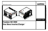
<strong>Series</strong> <strong>Battery</strong> <strong>Charger</strong>
Truecharge 2<br />
<strong>Series</strong> <strong>Battery</strong><br />
<strong>Charger</strong>s<br />
Owner’s Guide
About <strong>Xantrex</strong><br />
<strong>Xantrex</strong> Technology Inc. is a world-leading supplier of advanced power electronics and<br />
controls with products ranging from small mobile units to utility-scale systems for wind,<br />
solar, batteries, fuel cells, microturbines, and backup power applications in both gridconnected<br />
and stand-alone systems. <strong>Xantrex</strong> products include inverters, battery chargers,<br />
programmable power supplies, and variable speed drives that convert, supply, control,<br />
clean, and distribute electrical power.<br />
Trademarks<br />
<strong>Xantrex</strong> Truecharge 2 <strong>Series</strong> <strong>Battery</strong> <strong>Charger</strong> is a trademark of <strong>Xantrex</strong> International.<br />
<strong>Xantrex</strong> is a registered trademark of <strong>Xantrex</strong> International.<br />
Other trademarks, registered trademarks, and product names are the property of their<br />
respective owners and are used herein for identification purposes only.<br />
Notice of Copyright<br />
Truecharge 2 <strong>Series</strong> <strong>Battery</strong> <strong>Charger</strong> Owner’s Guide © September 2008 <strong>Xantrex</strong><br />
International. No part of this document may be reproduced in any form or disclosed to<br />
third parties without the express written consent of:<br />
<strong>Xantrex</strong> International<br />
Suite #3, Stafford House, The Garrison,<br />
St. Michael, Barbados<br />
<strong>Xantrex</strong> International reserves the right to revise this document and to periodically make<br />
changes to the content hereof without obligation or organization of such revisions or<br />
changes unless required to do so by prior arrangement.<br />
Exclusion for Documentation<br />
UNLESS SPECIFICALLY AGREED TO IN WRITING, XANTREX TECHNOLOGY INC. (“XANTREX”)<br />
(A) MAKES NO WARRANTY AS TO THE ACCURACY, SUFFICIENCY OR SUITABILITY OF ANY TECHNICAL<br />
OR OTHER INFORMATION PROVIDED IN ITS MANUALS OR OTHER DOCUMENTATION.<br />
(B) ASSUMES NO RESPONSIBILITY OR LIABILITY FOR LOSSES, DAMAGES, COSTS OR EXPENSES,<br />
WHETHER SPECIAL, DIRECT, INDIRECT, CONSEQUENTIAL OR INCIDENTAL, WHICH MIGHT ARISE OUT OF<br />
THE USE OF SUCH INFORMATION. THE USE OF ANY SUCH INFORMATION WILL BE ENTIRELY AT THE<br />
USER’S RISK; AND<br />
(C) REMINDS YOU THAT IF THIS MANUAL IS IN ANY LANGUAGE OTHER THAN ENGLISH, ALTHOUGH<br />
STEPS HAVE BEEN TAKEN TO MAINTAIN THE ACCURACY OF THE TRANSLATION, THE ACCURACY<br />
CANNOT BE GUARANTEED. APPROVED XANTREX CONTENT IS CONTAINED WITH THE ENGLISH<br />
LANGUAGE VERSION WHICH IS POSTED AT WWW.XANTREX.COM.<br />
Date and Revision Document Part Number<br />
September 2008 Rev B 975-0401-01-01<br />
Product Numbers<br />
804-1210, 804-1215, 804-1220, 804-1230, 804-1240, 804-1250, 804-1260, 804-2415,<br />
804-2420, 804-2430, 804-2450<br />
Contact Information<br />
Telephone: 1 800 670 0707 (toll free North America)<br />
1 408 987 6030 (direct)<br />
+34 93 470 5330 (Europe)<br />
Fax: 1 800 994 7828 (toll free North America)<br />
+34 93 473 6093 (Europe)<br />
Email: customerservice@xantrex.com<br />
Web: www.xantrex.com
About This Guide<br />
Purpose<br />
The purpose of this Owner’s Guide is to provide explanations and<br />
procedures for operating, maintaining, and troubleshooting the <strong>Xantrex</strong><br />
Truecharge 2 <strong>Series</strong> <strong>Battery</strong> <strong>Charger</strong>.<br />
Scope<br />
The Guide provides safety and operating guidelines as well as<br />
information about troubleshooting the unit. It does not provide details<br />
about particular brands of batteries. Please consult individual battery<br />
manufacturers for this information.<br />
Audience<br />
The Guide is intended for users and operators of the <strong>Xantrex</strong><br />
Truecharge 2 <strong>Series</strong> <strong>Battery</strong> <strong>Charger</strong>.<br />
Organization<br />
This Guide is organized into three chapters and one appendix.<br />
Chapter 1 describes the standard features of a Truecharge 2 <strong>Battery</strong><br />
<strong>Charger</strong>, as well as its protection features. It also provides information on<br />
the different parts of the Truecharge 2 <strong>Battery</strong> <strong>Charger</strong> including<br />
information on the optional remote panel.<br />
Chapter 2 describes the operating states and provides procedures for<br />
charging a battery and performing an equalization.<br />
Chapter 3 contains information and procedures for troubleshooting your<br />
Truecharge 2 <strong>Battery</strong> <strong>Charger</strong>.<br />
Appendix A contains physical, electrical performance, and regulatory<br />
approval specifications for the Truecharge 2 <strong>Battery</strong> <strong>Charger</strong>.<br />
iii
About This Guide<br />
Conventions Used<br />
The following conventions are used in this guide.<br />
WARNING<br />
Warnings identify conditions or practices that could result in<br />
personal injury or loss of life.<br />
CAUTION<br />
Cautions identify conditions or practices that could result in<br />
damage to the unit or other equipment.<br />
Important: These notes describe things which are important<br />
for you to know, but not as serious as a caution or warning.<br />
This Guide contains information for 11 product models of the<br />
<strong>Xantrex</strong> Truecharge 2 <strong>Series</strong> <strong>Battery</strong> <strong>Charger</strong>.<br />
The 12V models are: TC1012, TC1512, TC2012, TC3012,<br />
TC4012, TC5012, and TC6012. When being referred to<br />
individually, the product will be referred to by its model<br />
name.<br />
The 24V models are: TC1524, TC2024, TC3024, and<br />
TC5024. When being referred to individually, the product<br />
will be referred to by its model name.<br />
When all models are being referred to, they will be referred to<br />
as Truecharge 2 <strong>Battery</strong> <strong>Charger</strong>s.<br />
Related Information<br />
You can find more information about <strong>Xantrex</strong> Technology Inc. as well as<br />
its products and services at www.xantrex.com<br />
iv 975-0401-01-01
Important Safety Instructions<br />
READ AND SAVE THIS OWNER’S GUIDE FOR FUTURE<br />
REFERENCE.<br />
This chapter contains important safety and operating<br />
instructions for the <strong>Xantrex</strong> Truecharge 2 <strong>Series</strong> <strong>Battery</strong><br />
<strong>Charger</strong>s.<br />
1. Before using a Truecharge 2 <strong>Battery</strong> <strong>Charger</strong>, read all<br />
instructions and cautionary markings on the<br />
Truecharge 2 <strong>Battery</strong> <strong>Charger</strong> unit, the batteries, and<br />
all appropriate sections of this guide.<br />
WARNING: Risk of injury<br />
To reduce the risk of injury, charge only properly rated (such as<br />
12 V and 24 V) lead-acid (GEL, AGM, Flooded, or leadcalcium)<br />
rechargeable batteries. Other battery types may burst,<br />
causing personal injury and damage.<br />
2. Do not operate this product unless it has been installed by<br />
a qualified installer in accordance with the Truecharge<br />
2 <strong>Battery</strong> <strong>Charger</strong> Installation Guide.<br />
3. Do not expose the Truecharge 2 <strong>Battery</strong> <strong>Charger</strong> to<br />
rain, snow, spray, or bilge water. To reduce risk of fire<br />
hazard, do not cover or obstruct the air intake vent<br />
openings. Do not install the Truecharge 2 <strong>Battery</strong><br />
<strong>Charger</strong> in a zero-clearance compartment. Overheating<br />
may result.<br />
v
Safety<br />
4. This appliance is not intended for use by persons<br />
(including children) with reduced physical, sensory, or<br />
mental capabilities or lack of experience and knowledge,<br />
unless they have been given supervision or instruction<br />
concerning use of the appliance by a person responsible<br />
for their safety. Children should be supervised to ensure<br />
that they do not play with the appliance.<br />
5. To avoid a risk of fire and electric shock, make sure that<br />
all wiring is in good condition and is not undersized. Do<br />
not operate the Truecharge 2 <strong>Battery</strong> <strong>Charger</strong> with<br />
damaged or substandard wiring.<br />
6. Do not operate the Truecharge 2 <strong>Battery</strong> <strong>Charger</strong> if it<br />
has received a sharp blow, been dropped, has cracks or<br />
openings in the enclosure including if the fuse cover has<br />
been lost, damaged, or will not close, or otherwise<br />
damaged in any other way. If the Truecharge 2 <strong>Battery</strong><br />
<strong>Charger</strong> is damaged, see the Warranty section.<br />
7. Do not disassemble the Truecharge 2 <strong>Battery</strong><br />
<strong>Charger</strong>—there are hazardous voltages within. It contains<br />
no user-serviceable parts. See Warranty for instructions<br />
on obtaining service. Attempting to service the<br />
Truecharge 2 <strong>Battery</strong> <strong>Charger</strong> yourself may result in a<br />
risk of electrical shock or fire and will void your<br />
warranty. Internal capacitors remain charged after all<br />
power is disconnected.<br />
8. To reduce the risk of electrical shock, disconnect both<br />
AC and DC power from the Truecharge 2 <strong>Battery</strong><br />
<strong>Charger</strong> before attempting any maintenance or cleaning<br />
or working on any circuits connected to the Truecharge<br />
2 <strong>Battery</strong> <strong>Charger</strong>. Turning off using the on/standby<br />
button on the remote panel will not reduce this risk.<br />
vi 975-0401-01-01
Safety<br />
9. The Truecharge 2 <strong>Battery</strong> <strong>Charger</strong> must be provided<br />
with equipment-grounding conductors connected to the<br />
AC input ground and to the DC chassis ground.<br />
WARNING: Explosion hazard<br />
10. Working in the vicinity of lead-acid batteries is<br />
dangerous. Batteries generate explosive gases during<br />
normal operation. Therefore, it is of utmost importance<br />
that you read this manual and follow the instructions<br />
exactly each time you use the charger.<br />
11. To reduce the risk of battery explosion, follow these<br />
instructions and those published by the battery<br />
manufacturer and the manufacturer of any equipment you<br />
intend to use in the vicinity of the battery. Review<br />
cautionary markings on these products and on the engine.<br />
Personal Precautions When Working With<br />
Batteries<br />
WARNING: BATTERIES PRESENT RISK OF<br />
ELECTRICAL SHOCK, BURN FROM HIGH SHORT-<br />
CIRCUIT CURRENT, FIRE OR EXPLOSION FROM<br />
VENTED GASES. OBSERVE PROPER PRECAUTIONS.<br />
1. Have someone within range of your voice or close<br />
enough to come to your aid when you work near a leadacid<br />
battery.<br />
2. Have plenty of fresh water and soap nearby in case<br />
battery acid contacts skin, clothing, or eyes.<br />
975-0401-01-01 vii
Safety<br />
3. Wear proper, non-absorbent gloves, complete eye<br />
protection, and clothing protection. Avoid touching your<br />
eyes and wiping your forehead while working near<br />
batteries.<br />
4. If battery acid contacts skin or clothing, wash<br />
immediately with soap and water. If acid enters your eye,<br />
immediately flood it with running cold water for at least<br />
twenty minutes and get medical attention immediately.<br />
5. Never smoke or allow a spark or flame near the engine or<br />
batteries.<br />
6. Use extra caution to reduce the risk or dropping a metal<br />
tool on the battery. It could spark or short circuit the<br />
battery or other electrical parts and could cause an<br />
explosion.<br />
7. Remove all personal metal items, like rings, bracelets,<br />
and watches when working with batteries. Batteries can<br />
produce a short circuit current high enough to weld a ring<br />
or metal bracelet or the like to the battery terminal,<br />
causing a severe burn.<br />
8. If you need to remove a battery, always remove the<br />
negative terminal from the battery first for systems with<br />
grounded negative. If it is grounded positive, remove the<br />
positive terminal first. Make sure all loads connected to<br />
the battery accessories are off so you don’t cause an arc.<br />
9. Never charge a frozen battery.<br />
PREPARING TO CHARGE<br />
10. Make sure the area around the battery is well ventilated.<br />
11. Make sure the voltage of the batteries matches the output<br />
voltage of the battery charger.<br />
12. Clean battery terminals. Be careful to keep corrosion<br />
from coming into contact with your eyes and skin.<br />
viii 975-0401-01-01
Safety<br />
13. Study and follow all of the battery manufacturer's<br />
specific precautions, such as removing or not removing<br />
cell caps while charging, whether equalization is<br />
acceptable for your battery, and recommended rates of<br />
charge.<br />
14. For flooded non-sealed batteries, add distilled water in<br />
each cell until battery acid reaches the level specified by<br />
the battery manufacturer. This helps to purge excessive<br />
gas from cells. Do not overfill. For a battery without<br />
removable cell caps, carefully follow manufacturer's<br />
instructions.<br />
BATTERY CHARGER LOCATION<br />
15. Locate the Truecharge 2 <strong>Battery</strong> <strong>Charger</strong> unit away<br />
from batteries in a well ventilated compartment.<br />
16. Never place the Truecharge 2 <strong>Battery</strong> <strong>Charger</strong> unit<br />
directly above batteries; gases from a battery will corrode<br />
and damage the charger<br />
17. Never allow battery acid to drip on the charger when<br />
reading gravity, or filling battery.<br />
18. Do not operate the charger in a closed in area, or restrict<br />
the ventilation in any way.<br />
19. Do not place a battery on top of the charger.<br />
20. For North American marine installations, external<br />
connections to the charger shall comply with the United<br />
States Coast Guard Electrical Regulations (33CFR183,<br />
Sub Part I).<br />
975-0401-01-01 ix
Safety<br />
FCC Information to the User<br />
This equipment has been tested and found to comply with the<br />
limits for a Class B digital device, pursuant to part 15 of the<br />
FCC Rules. These limits are designed to provide reasonable<br />
protection against harmful interference in a residential<br />
installation. This equipment generates, uses, and can radiate<br />
radio frequency energy and, if not installed and used in<br />
accordance with the instructions, may cause harmful<br />
interference to radio communications.<br />
However, there is no guarantee that interference will not<br />
occur in a particular installation. If this equipment does cause<br />
harmful interference to radio or television reception, which<br />
can be determined by turning the equipment off and on, the<br />
user is encouraged to try to correct the interference by one or<br />
more of the following measures:<br />
• Reorient or relocate the receiving antenna.<br />
• Increase the separation between the equipment and<br />
receiver.<br />
• Connect the equipment into an outlet on a circuit<br />
different from that to which the receiver is connected.<br />
Consult the dealer or an experienced radio/TV technician for<br />
help.<br />
x 975-0401-01-01
Contents<br />
Important Safety Instructions- - - - - - - - - - - - - - - - - - - - v<br />
1 Introduction<br />
Truecharge 2 <strong>Battery</strong> <strong>Charger</strong> - - - - - - - - - - - - - - - - - - - - - 1–1<br />
Standard and Protection Features - - - - - - - - - - - - - - - - - - - - 1–2<br />
Truecharge 2 <strong>Battery</strong> <strong>Charger</strong> - - - - - - - - - - - - - - - - - - - - - 1–4<br />
Rear Panel- - - - - - - - - - - - - - - - - - - - - - - - - - - - - - - - - - - - 1–6<br />
Onboard Control and Status Display Panel - - - - - - - - - - - - - - 1–7<br />
Input Voltage Operating and Derating - - - - - - - - - - - - - -1–13<br />
<strong>Battery</strong> and <strong>Charger</strong> Temperature Thresholds - - - - - - - - -1–13<br />
Remote Panel (Sold Separately) - - - - - - - - - - - - - - - - - - - - -1–14<br />
Advantages of Current Limiting Feature: - - - - - - - - -1–17<br />
2 Operation<br />
About Truecharge 2 <strong>Battery</strong> <strong>Charger</strong> - - - - - - - - - - - - - - - - 2–2<br />
Three-Stage Charging - - - - - - - - - - - - - - - - - - - - - - - - - 2–3<br />
Two-Stage Charging - - - - - - - - - - - - - - - - - - - - - - - - - 2–4<br />
Charging Voltage Setpoints - - - - - - - - - - - - - - - - - - - - - 2–5<br />
<strong>Battery</strong> Qualification - - - - - - - - - - - - - - - - - - - - - - - - - 2–5<br />
Temperature Considerations - - - - - - - - - - - - - - - - - - - - 2–6<br />
Setting the <strong>Battery</strong> Temperature without a BTS - - - - - - - 2–6<br />
Operating DC Loads - - - - - - - - - - - - - - - - - - - - - - - - - - 2–8<br />
Charging Batteries - - - - - - - - - - - - - - - - - - - - - - - - - - - - - - 2–9<br />
Equalizing Flooded Batteries - - - - - - - - - - - - - - - - - - - - - - -2–11<br />
About Equalization - - - - - - - - - - - - - - - - - - - - - - - - - -2–11<br />
Performing An Equalization - - - - - - - - - - - - - - - - - - - -2–12<br />
Transitioning the Truecharge 2 <strong>Battery</strong> <strong>Charger</strong> to<br />
ON, Standby, or Disabled - - - - - - - - - - - - - - - - - - - - - - - - -2–14<br />
Accessing <strong>Charger</strong> Information - - - - - - - - - - - - - - - - - - - - -2–15<br />
Reading Remote Panel and Onboard Display LEDs - - - - -2–15<br />
xi
Contents<br />
Reporting While Charging or Equalizing - - - - - - - - - - - -2–15<br />
Reporting Without AC Power or While on Standby - - - - -2–16<br />
Using A Generator As Source Power - - - - - - - - - - - - - -2–16<br />
3 Troubleshooting<br />
Care and Maintenance- - - - - - - - - - - - - - - - - - - - - - - - - - - - 3–2<br />
Indicator LEDs on the Onboard Display Panel and<br />
Optional Remote Panel - - - - - - - - - - - - - - - - - - - - - - - - - - - 3–3<br />
Replacing the DC Output Fuse - - - - - - - - - - - - - - - - - - - - - -3–11<br />
Troubleshooting - - - - - - - - - - - - - - - - - - - - - - - - - - - - - - - -3–13<br />
A<br />
Specifications<br />
Physical Specifications - - - - - - - - - - - - - - - - - - - - - - - - - - - A–2<br />
Electrical Specifications - - - - - - - - - - - - - - - - - - - - - - - - - - A–3<br />
AC Input Specifications - - - - - - - - - - - - - - - - - - - - - - - A–3<br />
DC Output Specifications - - - - - - - - - - - - - - - - - - - - - - A–4<br />
Environmental Specifications - - - - - - - - - - - - - - - - - - - - - - - A–5<br />
Protection Features - - - - - - - - - - - - - - - - - - - - - - - - - - - - - - A–6<br />
Approvals - - - - - - - - - - - - - - - - - - - - - - - - - - - - - - - - - - - - A–7<br />
Warranty and Return Information - - - - - - - - - - - - WA–1<br />
xii 975-0401-01-01
1 Introduction<br />
Chapter 1 describes the standard features of a<br />
Truecharge 2 <strong>Battery</strong> <strong>Charger</strong>, as well as its<br />
protection features. It also provides information on the<br />
different parts of the Truecharge 2 <strong>Battery</strong> <strong>Charger</strong><br />
including information on the optional remote panel.<br />
Truecharge 2 <strong>Battery</strong> <strong>Charger</strong><br />
The Truecharge 2 <strong>Battery</strong> <strong>Charger</strong> ships with the following<br />
items.<br />
• one Truecharge 2 <strong>Battery</strong> <strong>Charger</strong> unit<br />
• installation and operation guides<br />
• rubber boots for DC terminals<br />
• nuts and washers<br />
• strain relief clamp for AC input cables<br />
• three crimp connectors for AC wiring<br />
Note: Keep the carton and packing material in case you need to<br />
return the Truecharge 2 <strong>Battery</strong> <strong>Charger</strong> for servicing.
Introduction<br />
Standard and Protection Features<br />
The Truecharge 2 <strong>Battery</strong> <strong>Charger</strong> provides the following<br />
standard features:<br />
• three 1 full current rated outputs<br />
• battery monitoring functions while in float mode or rest<br />
mode<br />
• correct charging voltage for batteries when connected to<br />
almost any single phase AC power outlet in the world<br />
• low electromagnetic interference (EMI)<br />
• automatic charge resumption, if required, after AC power<br />
interruption<br />
• programmable custom charge settings 2<br />
• fully discharged battery charging 3<br />
The Truecharge 2 <strong>Battery</strong> <strong>Charger</strong> provides the following<br />
protection features:<br />
• battery reverse polarity protection via a replaceable<br />
output fuse<br />
• AC input out-of-range derating and shutdown<br />
• ambient over temperature derating and shutdown<br />
• battery over-charging protection<br />
• electronic current limiting provides protection against<br />
short circuit conditions on the charger’s output<br />
• ignition protected rating, enabling installation in engine<br />
spaces<br />
• isolated design<br />
1.Model TC1012 has one output and model TC1512 has two outputs. All other models<br />
have three outputs. Each output (for models with 2 or 3 outputs) can charge different batteries<br />
that either have the same chemistry or can tolerate the same charge sequence.<br />
2.The charger can be programmed with custom charge setpoints using PC interface. This<br />
programming can only be done using a special configuration tool operated by <strong>Xantrex</strong> or a<br />
designated OEM.<br />
3.The charger can initiate charging a non-damaged but zero voltage battery.<br />
1–2 975-0401-01-01
Standard and Protection Features<br />
• short circuit protection for the BTS and communication<br />
connector ports including protection from incorrectly<br />
inserting the remote panel communication cable plug into<br />
the BTS port and vice versa<br />
• drip-proof rubber boots for DC terminals for added<br />
moisture protection<br />
• IP-32 drip protection rating 1<br />
• locked fan 2 protection<br />
The Truecharge 2 <strong>Battery</strong> <strong>Charger</strong> provides the following optional<br />
features:<br />
• an optional remote panel 3 which can be mounted up to<br />
15 m (50 ft) away for remote control and monitoring.<br />
• an optional battery temperature sensor 4 (BTS) provides<br />
battery temperature voltage compensation from 0 to<br />
70 °C (-13 to 158 °F)<br />
The optional <strong>Battery</strong> Temperature Sensor (BTS) provides these<br />
protection features:<br />
• battery under temperature charging protection preventing<br />
battery charging at -25 °C or below<br />
• battery over temperature charging protection preventing<br />
battery charging at 70 °C or higher<br />
• charging voltage compensation based on the temperature<br />
of the battery the optional BTS is connected to<br />
1.In two specific installation orientations–see Figure 2-2, “Truecharge 2 <strong>Battery</strong> <strong>Charger</strong><br />
Mounting Orientations” on page 2–7 of the Installation Guide.<br />
2.A locked fan occurs when the fan’s blades are hindered from turning by objects such as<br />
insects or accumulated debris that can obstruct the fan’s operation. The Truecharge 2<br />
<strong>Battery</strong> <strong>Charger</strong> sounds an alarm if the fan suddenly stops turning. If the fan does not<br />
resume turning after a minute, the charger reports a fault and immediately stops charging.<br />
3.Part number: 808-8040-00<br />
4.Part number: 808-0232-01<br />
975-0401-01-01 1–3
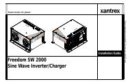
Introduction<br />
Truecharge 2 <strong>Battery</strong> <strong>Charger</strong><br />
This section describes the different parts of the Truecharge<br />
2 <strong>Battery</strong> <strong>Charger</strong>.<br />
1<br />
2<br />
3<br />
5<br />
4<br />
6<br />
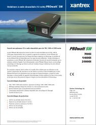
Figure 1-1 Truecharge 2 <strong>Battery</strong> <strong>Charger</strong><br />
Item<br />
Description<br />
1 Onboard control and status display panel or simply<br />
onboard display (see “Rear Panel” on page 1–6 for<br />
more information) for controlling the Truecharge 2<br />
<strong>Battery</strong> <strong>Charger</strong> settings and for monitoring charger<br />
status and charging current.<br />
2 Mounting flanges are used to permanently install the<br />
product.<br />
3 DC wiring compartment cover protects the DC<br />
terminals, as well as the communication and BTS ports.<br />
Remove and replace when installing cables.<br />
1–4 975-0401-01-01
Item<br />
Description<br />
Truecharge 2 <strong>Battery</strong> <strong>Charger</strong><br />
4 Fuse access panel cover provides access to the DC fuse<br />
in the event of an accidental reverse battery polarity<br />
installation.<br />
WARNING: Shock hazard<br />
Disconnect the batteries and AC power before opening<br />
the fuse access panel.<br />
5 AC wiring compartment cover provides the installer<br />
with easy access to the AC wiring compartment, to<br />
allow for a trouble free installation. Remove and replace<br />
when installing the product.<br />
6 DC ground stud for connecting the charger’s chassis to<br />
ground.<br />
975-0401-01-01 1–5
Introduction<br />
Rear Panel<br />
This section describes the parts of the rear panel of the<br />
Truecharge 2 <strong>Battery</strong> <strong>Charger</strong>.<br />
8<br />
7<br />
4<br />
3<br />
9<br />
5<br />
2<br />
6<br />
1<br />
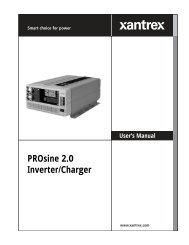
40 A model (TC4012) shown. Other models may vary.<br />
Figure 1-2 Truecharge 2 <strong>Battery</strong> <strong>Charger</strong> Rear Panel<br />
Item<br />
Description<br />
1 BTS port- battery temperature sensor port<br />
2 Communication port - remote panel port<br />
3 <strong>Battery</strong> positive (+) for bank 3 (6 mm stud)<br />
4 <strong>Battery</strong> positive (+) for bank 2 (6 mm stud)<br />
5 <strong>Battery</strong> positive (+) for bank 1 (6 mm stud)<br />
6 <strong>Battery</strong> negative (–), common for all three banks<br />
(6 mm stud)<br />
(common for both banks in model TC1512)<br />
(model TC1012 has a single bank only–one positive<br />
terminal and one negative terminal)<br />
7 Air intake vent - located inside is the fan assembly<br />
8 AC wiring compartment<br />
9 AC pigtail wiring - line, neutral, and ground input<br />
wires<br />
1–6 975-0401-01-01
Onboard Control and Status Display Panel<br />
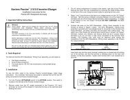
Onboard Control and Status Display Panel<br />
This section describes the parts of the onboard control and<br />
status display panel of the Truecharge 2 <strong>Battery</strong> <strong>Charger</strong>.<br />
Important: To prevent any unintentional changes in the setting,<br />
“press and hold” for three seconds any Select panel button to<br />
advance and pick the right setting.<br />
To set and cancel an equalization program, “press and hold” for<br />
five seconds both the <strong>Charger</strong> Mode and <strong>Battery</strong> Temp. Select<br />
panel buttons.<br />
1<br />
3<br />
4<br />
2<br />
5<br />
6<br />
Figure 1-3 Onboard Control and Status Display Panel<br />
To reduce current draw from the connected battery when AC<br />
power is not present, the panel’s LED control and status<br />
lights are automatically turned off and the buttons are<br />
disabled.<br />
However, to temporarily check the status of the connected<br />
battery when AC power is not present, press the Status button<br />
on the optional remote panel.<br />
975-0401-01-01 1–7
Introduction<br />
Item<br />
Description<br />
1 Charging Output (%) LEDs<br />
• The LEDs illuminate like a bar graph displaying the present total<br />
output charge current as a percentage of the maximum rated<br />
charge current. For example, unit model TC4012 has a maximum<br />
rated charge current of 40 A so at 60% the charger’s current output<br />
is 24 A. The numbers below the LEDs represent the percentage<br />
values. See Figure 1-4 on page 1–10.<br />
NOTE: When the maximum Charge Output current is limited via<br />
the optional Remote panel, the LEDs will still display the total<br />
charge output current as a percentage of the maximum rated<br />
charge current and NOT as a percentage of the limited charge<br />
current.<br />
• One or two LEDs may flash intermittently in combination with a<br />
solid Fault LED (indicating a fault) or with a flashing Fault LED<br />
(indicating a warning). The icons above the LEDs represent the<br />
various types of fault and warning conditions. See Figure 1-4 on<br />
page 1–10.<br />
2 Fault LED<br />
The LED may illuminate a solid light (indicating a fault) or flash<br />
intermittently (indicating a warning) in combination with flashing<br />
Charging Output (%) LEDs. See Table 1-1, “Fault and Warning<br />
Indicators” on page 1–11 for details.<br />
3 <strong>Charger</strong> Status LEDs<br />
Displays the current status of the charger.<br />
• Ready - a solid light indicates batteries are fully charged and the<br />
charger is not in float stage.<br />
• Ready and Charging - solid lights indicate batteries are fully<br />
charged and the charger is in float stage.<br />
• Charging - a solid light indicates charger is performing a normal<br />
charge cycle.<br />
• Equalize - a solid light indicates that the charger is performing an<br />
equalization cycle.<br />
- a flashing light indicates that the equalization cycle<br />
will begin after the absorption stage is done.<br />
1–8 975-0401-01-01
Item<br />
Description<br />
Onboard Control and Status Display Panel<br />
4 <strong>Charger</strong> Mode Select button<br />
• Press and hold the button for three seconds to select either of two<br />
settings. An indicator LED corresponds to each setting. Each<br />
setting optimizes the charging sequence differently in charging the<br />
batteries by stages.<br />
• Three-stage - Bulk, Absorption, and Float; default setting<br />
• Two-stage - Bulk and Absorption only<br />
• When setting or cancelling an Equalization program: Press and<br />
hold for five seconds both the <strong>Charger</strong> Mode and <strong>Battery</strong> Temp.<br />
Select buttons.<br />
5 <strong>Battery</strong> Type Select button<br />
Press and hold the button for three seconds to select either of five<br />
settings. An indicator LED corresponds to each setting. Each setting<br />
maximizes charger performance for its corresponding battery type.<br />
• AGM - Absorbent Glass Mat lead-acid battery<br />
• Flooded - Lead-acid battery; default setting<br />
• GEL - Gel-type lead-acid battery<br />
• Lead Calc. - Lead-calcium battery<br />
• Custom - If a custom battery type has been programmed then all<br />
LEDs will illuminate<br />
6 <strong>Battery</strong> Temp. Select button<br />
• Press and hold the button for three seconds to select one of three<br />
settings. An indicator LED corresponds to each setting.<br />
When the optional BTS is not used, this selection changes the<br />
charger's output voltage settings to compensate for the battery<br />
temperature selected. The Cold setting raises the voltages, and the<br />
Hot setting lowers the voltages.<br />
WARNING: Risk of battery damage<br />
Be sure the appropriate setting is selected before charging. For<br />
varying conditions, use the Warm setting.<br />
975-0401-01-01 1–9
Introduction<br />
Item<br />
6<br />
continued<br />
Description<br />
• Cold - for battery temperature below 5 °C (41 °F); raises the<br />
charging voltage to compensate<br />
• Warm - for battery temperature between 5 and 30 °C<br />
(41 and 86 °F); default setting<br />
• Hot - for battery temperature above 30 °C (86 °F); lowers<br />
charging voltage to compensate<br />
• When setting or cancelling an Equalization program: Press and<br />
hold for five seconds both the <strong>Charger</strong> Mode and <strong>Battery</strong> Temp.<br />
Select buttons.<br />
The Fault LED works in conjunction with the Charging<br />
Current (%) LEDs. The icons at the top row above the<br />
Charging Current (%) LEDs represent the various types of<br />
fault and warning conditions. For example, a temperature<br />
warning is represented by a thermometer icon.<br />
The Charging Current (%) LEDs will normally illuminate as<br />
a solid progress bar when they are indicating the amount of<br />
output charging current. If any of the LEDs start to flash<br />
intermittently at the same time that the Fault LED is either<br />
solid or flashing, a fault or warning condition is indicated.<br />
Important: A warning condition notifies the user of an<br />
impending problem and will not stop the charger from<br />
charging, while a fault condition will stop the charger from<br />
charging the battery.<br />
Charging Output (%)<br />
Onboard Control and Status Display Panel<br />
Table 1-1 on page 1–11 summarizes the various fault<br />
conditions that might occur during the operation of the<br />
charger. For suggestions in what to do after a fault condition<br />
is detected, see Table 3-1, “Interpreting Fault and Warning<br />
Indicators” on page 3–4 in Chapter 3, “Troubleshooting”.<br />
Table 1-1 Fault and Warning Indicators<br />
Fault or Warning<br />
Condition<br />
Temp Fan AC <strong>Battery</strong> Fuse <strong>Charger</strong> Remote Fault<br />
F C R<br />
u h<br />
s g e<br />
e r m<br />
High <strong>Battery</strong> Temp<br />
warning; >50°C<br />
See Figure 1-5.<br />
High <strong>Battery</strong> Temp<br />
fault; >70°C<br />
See Figure 1-5.<br />
Low <strong>Battery</strong> Temp<br />
warning;
Introduction<br />
Table 1-1 Fault and Warning Indicators<br />
Fault or Warning<br />
Condition<br />
Temp Fan AC <strong>Battery</strong> Fuse <strong>Charger</strong> Remote Fault<br />
F C R<br />
u h<br />
s g e<br />
e r m<br />
<strong>Charger</strong> Output over<br />
voltage fault; >16.6V<br />
High <strong>Charger</strong> Temp<br />
warning; >50°C<br />
High <strong>Charger</strong> Temp<br />
fault; >65°C<br />
Locked Fan warning<br />
(for ten seconds a )<br />
Locked Fan fault<br />
(after one minute b )<br />
Loss of Remote<br />
Connection warning<br />
Reverse Polarity Fuse<br />
fault<br />
Internal fault<br />
Flashing LED<br />
Solid LED<br />
a.The Truecharge 2 <strong>Battery</strong> <strong>Charger</strong> sounds an alarm and reports a warning via LED for<br />
ten seconds immediately after the fan locks (stops turning).<br />
b. If the fan does not resume turning after a minute of being locked, the charger sounds an<br />
alarm, reports a fault via LED, and immediately stops charging.<br />
1–12 975-0401-01-01
Input Voltage Operating and Derating<br />
Onboard Control and Status Display Panel<br />
When there is an AC input out of range warning in the lower<br />
range between 90–108 Vac, the Truecharge 2 <strong>Battery</strong><br />
<strong>Charger</strong> derates to 80% of maximum current.<br />
However, when AC input increases above 108 Vac up to<br />
255 Vac, maximum current returns to 100% capacity.<br />
Furthermore, the Truecharge 2 <strong>Battery</strong> <strong>Charger</strong> will<br />
continue to operate at 100% of maximum current, even while<br />
there is an AC input out of range warning in the upper range<br />
between 256–265 Vac.<br />
<strong>Battery</strong> and <strong>Charger</strong> Temperature Thresholds<br />
FAULT set<br />
ALARM set<br />
ALARM set<br />
FAULT set<br />
FAULT reset ALARM reset ALARM reset FAULT reset<br />
-25 -20 -15 -10 -5 0 +5 +10 +20 +30 +40 +50 +60 +70 °C<br />
COLD (default 0 °C) WARM (default 25 °C) HOT (default 35 °C)<br />
<strong>Charger</strong><br />
ALARM set<br />
<strong>Charger</strong><br />
FAULT set<br />
<strong>Charger</strong><br />
ALARM reset<br />
<strong>Charger</strong><br />
FAULT reset<br />
-25 -20 -15 -10 -5 0 5 10 15 20 25 30 35 40 45 50 55 60 65 70 °C<br />
Ambient Temperature<br />
derating to<br />
80% Imax.<br />
Figure 1-5 <strong>Battery</strong> and <strong>Charger</strong> Temperature Thresholds<br />
975-0401-01-01 1–13
Introduction<br />
Remote Panel (Sold Separately)<br />
This section describes the parts of the optional remote panel<br />
(Part number: 808-8040-00) of the Truecharge 2 <strong>Battery</strong><br />
<strong>Charger</strong>. The remote panel can be mounted using a<br />
communications cable up to 15 m (50 ft) from the<br />
Truecharge 2 <strong>Battery</strong> <strong>Charger</strong> connected via the<br />
communication port for convenience.<br />
2a<br />
2<br />
6a<br />
4<br />
6<br />
7<br />
1<br />
3<br />
Figure 1-6 Truecharge 2 <strong>Battery</strong> <strong>Charger</strong> Remote Panel (optional)<br />
5<br />
The Remote Panel can be used to:<br />
• Program the charger for battery type and temperature<br />
• Set the charger mode (two or three-stage charging)<br />
• Activate and terminate equalization (not allowed for<br />
GEL and AGM)<br />
• Limit the maximum charger output current (20, 40, 60,<br />
80, and 100% of charger rating) to lower the current<br />
drawn from the generator or AC source<br />
• Set the charger to ON or STANDBY<br />
• Set or cancel an equalization cycle<br />
• Display faults and warnings<br />
• Display basic battery level and settings<br />
1–14 975-0401-01-01<br />
8
Remote Panel (Sold Separately)<br />
Item<br />
Description<br />
1 ON/STANDBY Button<br />
• Press to enable or disable the charger while AC power is<br />
connected.<br />
• When in Setup Mode: Press to select the <strong>Charger</strong> Mode: two or<br />
three-stage.<br />
• To set or cancel an Equalization program: Press and hold both the<br />
Status and ON/STANDBY buttons for more than five seconds.<br />
2 Charging Output (%) LEDs<br />
• The LEDs illuminate like a bar graph displaying the present total<br />
output charge current as a percentage of the maximum rated<br />
charge current. For example, unit model TC4012 has a maximum<br />
rated charge current of 40 A so at 60% the charger’s current output<br />
is 24 A. The numbers to the left of the LEDs represent the<br />
percentage values. See 2a on Figure 1-6 on page 1–14.<br />
NOTE: When the maximum Charge Output current is limited by<br />
pressing the Set Max Output button, the LEDs will still display the<br />
total charge output current as a percentage of the maximum rated<br />
charge current and NOT as a percentage of the limited charge<br />
current.<br />
• An LED may flash intermittently in combination with a solid Fault<br />
LED to indicate a fault or with a flashing Fault LED to indicate a<br />
warning condition. The icons on the right side of the LEDs<br />
represent different types of faults and warnings. See 6a on Figure<br />
1-6 on page 1–14.<br />
3 <strong>Charger</strong> Status LEDs<br />
Displays the present status of the charger.<br />
• Ready - a solid light indicates that all batteries are fully charged<br />
and in rest stage.<br />
• Ready and Charging - solid lights indicate that batteries are fully<br />
charged and in float stage.<br />
• Charging - a solid light indicates that the charger is performing a<br />
normal charge cycle.<br />
• Equalize - a solid light indicates that the charger is performing an<br />
equalization cycle.<br />
- a flashing light indicates that the equalization cycle<br />
will begin after the absorption stage is done.<br />
975-0401-01-01 1–15
Introduction<br />
Item<br />
Description<br />
4 <strong>Battery</strong> Status LEDs<br />
Displays the present status of each battery (or each battery bank). This<br />
feature is available only on the Remote Panel.<br />
Each row represents the battery (or battery bank) number<br />
designation—1, 2, or 3. Each column represents Low, Medium, or<br />
Full battery capacity.<br />
NOTE: These levels are measured when the battery is not under<br />
charge during the 15-minute charge interruption intervals.<br />
The thresholds are:<br />
• Low if battery voltage is below 11.9 V (23.8 V for 24 Vdc<br />
systems)<br />
• Medium if the voltage is 11.9 to 12.4 V (23.8 to 24.8 V for<br />
24 Vdc systems)<br />
• Full if the voltage is above 12.4 V (24.8 V for 24 Vdc systems)<br />
5 Status Button<br />
• Press and hold to enter or exit Setup Mode.<br />
• When in Setup Mode: Press to select the <strong>Battery</strong> Temperature:<br />
Cold, Warm, or Hot.<br />
• When setting or cancelling an Equalization program: Press and<br />
hold both the Status and ON/STANDBY buttons.<br />
6 Fault/Warning LED<br />
The LED displays a solid light to indicate a fault condition or flashes<br />
intermittently in combination with a flashing Charging Output (%)<br />
LED to display a warning condition (6a). See Table 1-1, “Fault and<br />
Warning Indicators” on page 1–11 for details.<br />
7 Max. Output (%) LED<br />
The LED illuminates a solid light corresponding to the Maximum<br />
<strong>Charger</strong> Output % setting.<br />
1–16 975-0401-01-01
Remote Panel (Sold Separately)<br />
Item<br />
Description<br />
8 Set Max Output Button (see below)<br />
• Press to select and limit the maximum rated charge current. For<br />
example, the unit model TC4012 has a maximum rated charge<br />
current of 40 A. A setting from 100 to 80 by pressing the button<br />
once, will have a new limited maximum charge current of 32 A<br />
(80% of 40 A). This feature is available only on the Remote Panel.<br />
NOTE: The maximum rated charge current is the only output<br />
current rating affected by this button. All other output current<br />
ratings, such as the equalization charge current, will not be<br />
affected.<br />
• When in Setup Mode: Press to select the <strong>Battery</strong> Type: AGM,<br />
Flooded, GEL, Lead-Calcium, and OEM (if charger is<br />
programmed for OEM)<br />
Advantages of Current Limiting Feature:<br />
• Gives the user flexibility to custom charge according<br />
to the battery manufacturer’s instructions.<br />
• Allows batteries with a lower current rating to be<br />
charged safely without the need of a new charger.<br />
• Prolongs power consumption and prevents an<br />
overload of an AC source such as a generator by<br />
drawing less current.<br />
975-0401-01-01 1–17
1–18
2 Operation<br />
WARNING<br />
The battery charger must be properly installed in accordance with<br />
all local and application-specific codes and ordinances before it is<br />
used. For installation instructions, see Truecharge 2 <strong>Battery</strong><br />
<strong>Charger</strong> Installation Guide (doc. part number: 975-0402-01-01).<br />
Chapter 2 describes the operating states and provides<br />
procedures for charging a battery and performing an<br />
equalization.<br />
It covers the following:<br />
• “About Truecharge 2 <strong>Battery</strong> <strong>Charger</strong>” on<br />
page 2–2<br />
• “Charging Batteries” on page 2–9<br />
• “Equalizing Flooded Batteries” on page 2–11<br />
• “Transitioning the Truecharge 2 <strong>Battery</strong> <strong>Charger</strong><br />
to ON, Standby, or Disabled” on page 2–14<br />
• “Accessing <strong>Charger</strong> Information” on page 2–15
Operation<br />
About Truecharge 2 <strong>Battery</strong> <strong>Charger</strong><br />
Most Truecharge 2 <strong>Battery</strong> <strong>Charger</strong> models have three<br />
outputs that share the full rated current enabling it to charge<br />
three different batteries or battery banks that either have the<br />
same chemistry or can tolerate the same charge sequence and<br />
thresholds. Model TC1012 has only one output while model<br />
TC1512 has two outputs that share the full rated current<br />
output. The Truecharge 2 <strong>Battery</strong> <strong>Charger</strong> can perform<br />
either three-stage charging (Bulk, Absorption, and Float) or<br />
two-stage charging (Bulk and Absorption).<br />
Important: The battery banks are not galvanically isolated<br />
from each other. They share a common negative as shown in the<br />
diagram below.<br />
The negative bus to chassis connection as shown below may not<br />
be suitable in some applications.<br />
NOTE: Not to scale. For illustration purposes only.<br />
AC source<br />
Remote panel<br />
(optional)<br />
L<br />
N<br />
G<br />
L<br />
N<br />
G<br />
NOTE: In some jurisdictions a<br />
double-pole breaker may be<br />
required.<br />
BTS<br />
(optional)<br />
<strong>Battery</strong> banks<br />
Negative<br />
bus<br />
Figure 2-1 Typical Three-<strong>Battery</strong> Installation<br />
2–2 975-0401-01-01
Three-Stage Charging<br />
About Truecharge 2 <strong>Battery</strong> <strong>Charger</strong><br />
The three-stage charging mode employs the following<br />
sequence: Bulk, Absorption, and Float. During the Bulk<br />
stage the batteries are accepting a constant maximum current.<br />
In the Absorption stage, the battery voltage is held constant<br />
and the current declines. A battery will “gas” (produce<br />
hydrogen and oxygen) when its voltage exceeds the<br />
“gassing” voltage. Finally, in the Float stage, the charger<br />
continues to provide voltage at a lower level to maintain the<br />
battery in a fully charged state. If there is no load on the<br />
battery, it will typically draw very little current. The charger,<br />
however, is able to provide current to its full rating to power<br />
auxiliary DC loads on the battery.<br />
The charger will restart the charging cycle in the Bulk stage if<br />
the lowest battery voltage of the three banks drops below<br />
12.5 V (12 Vdc chargers) or 25 V (24 Vdc chargers) for 15<br />
minutes. After 21 days, the charger will automatically restart<br />
charging in order to refresh the batteries.<br />
<strong>Battery</strong> Voltage<br />
Vbat = Vgas<br />
for 1 minute<br />
Vbat = Vabs<br />
for 1 minute<br />
lout < 10% lrating<br />
for 1 minute<br />
Vbat < 12.5 V<br />
for 15 minutes<br />
Vgas voltage<br />
Charge<br />
start<br />
BULK<br />
ABS<br />
CC<br />
ABS<br />
CV<br />
FLOAT<br />
Start of<br />
charging cycle<br />
ABS CV timeout<br />
max 5 hrs<br />
Total ABS timeout<br />
max 8 hrs<br />
FLOAT timeout<br />
max 21 days<br />
Time<br />
Figure 2-2 Three-Stage Charging Process<br />
975-0401-01-01 2–3
Operation<br />
Two-Stage Charging<br />
The two-stage charging mode employs the following<br />
sequence: Bulk and Absorption. It runs similar to the threestage<br />
sequence except that there is no float stage; after the<br />
absorption stage the charger stops providing current to the<br />
battery and the charger output drops to 9 V (12 Vdc chargers)<br />
or 18V (24 Vdc chargers). In this manner, DC loads draw<br />
power supplied by batteries and the charger enters a “rest or<br />
standby stage.” Like the three-stage sequence, the charger<br />
will restart the charging cycle in the Bulk stage if the lowest<br />
battery voltage of the three banks drops below 12.5 V<br />
(12 Vdc chargers) or 25 V (24 Vdc chargers) for 15 minutes.<br />
After 21 days, the charger will automatically restart charging<br />
in order to refresh the batteries.<br />
<strong>Battery</strong> Voltage<br />
Vbat = Vgas<br />
for 1 minute<br />
Vbat = Vabs<br />
for 1 minute<br />
lout < 10% lrating<br />
for 1 minute<br />
Vgas voltage<br />
Charge<br />
start<br />
GO TO BULK when<br />
Vbat < 12.5 V for<br />
15 minutes<br />
BULK<br />
ABS<br />
CC<br />
ABS<br />
CV<br />
REST<br />
(Standby)<br />
Start of<br />
charging cycle<br />
ABS CV timeout<br />
max 5 hrs<br />
Total ABS timeout<br />
max 8 hrs<br />
REST (Standby)<br />
timeout max 21 days<br />
Time<br />
Figure 2-3 Two-Stage Charging Process<br />
2–4 975-0401-01-01
Charging Voltage Setpoints<br />
About Truecharge 2 <strong>Battery</strong> <strong>Charger</strong><br />
The Truecharge 2 <strong>Battery</strong> <strong>Charger</strong> charging process is<br />
designed to make the battery or battery banks reach the<br />
following voltage setpoints.<br />
Table 2-1 Charging Maximum Voltages for 12 Vdc chargers<br />
<strong>Battery</strong> Type<br />
Absorption<br />
(Volts) Float (Volts)<br />
Equalization<br />
(Volts)<br />
Flooded 14.4 13.5 16.0<br />
GEL 14.2 13.8 not applicable<br />
AGM 14.3 13.4 not applicable<br />
Lead-Calcium 15.5 13.5 16.0<br />
Table 2-2 Charging Maximum Voltages for 24 Vdc chargers<br />
<strong>Battery</strong> Type<br />
Absorption<br />
(Volts) Float (Volts)<br />
Equalization<br />
(Volts)<br />
Flooded 28.8 27.0 32.0<br />
GEL 28.4 27.6 not applicable<br />
AGM 28.6 26.8 not applicable<br />
Lead-Calcium 31.0 27.0 32.0<br />
<strong>Battery</strong> Qualification<br />
The Truecharge 2 <strong>Battery</strong> <strong>Charger</strong> will perform a battery<br />
qualification on each application of AC (or DC > 9 V), to<br />
determine if battery banks are present and healthy.<br />
To force a battery detection sequence,<br />
1. Turn off AC.<br />
2. Wait approximately 20 seconds or until all lights on the<br />
charger or remote have gone out.<br />
3. Turn on AC.<br />
The charger will then perform a battery detection when<br />
AC is reapplied<br />
975-0401-01-01 2–5
Operation<br />
The Truecharge 2 <strong>Battery</strong> <strong>Charger</strong> charges all banks at the<br />
same time but the bank in most need of charging is the one<br />
that receives the most charge. For example, if Bank 1 and<br />
Bank 2 are both charged, but Bank 1 has a load and Bank 2<br />
does not, then the charger may rarely charge Bank 2.<br />
Temperature Considerations<br />
<strong>Xantrex</strong> strongly recommends that you purchase and install<br />
the optional <strong>Battery</strong> Temperature Sensor (BTS) to protect<br />
your battery and improve charging accuracy. Attach the BTS<br />
to the warmest battery.<br />
If no BTS is connected, the charger defaults to the <strong>Battery</strong><br />
Temp. selection on the onboard display and remote panel.<br />
Setting the <strong>Battery</strong> Temperature without a BTS<br />
CAUTION: <strong>Battery</strong> damage<br />
In the absence of a BTS, setting a battery temperature that is lower<br />
than the actual temperature may cause the battery to be slightly<br />
overcharged. Consequently, it may damage or reduce the life of the<br />
battery or cause a hazard.<br />
Setting the temperature higher than the actual temperature will<br />
result in under-charging the battery.<br />
Always be aware of the temperature setting and observe the<br />
battery’s actual temperature. Adjust the <strong>Battery</strong> Temperature<br />
setting every time charging is done. For varying conditions, use the<br />
Warm setting.<br />
2–6 975-0401-01-01
About Truecharge 2 <strong>Battery</strong> <strong>Charger</strong><br />
Using the Onboard Display Panel<br />
To configure the battery temperature:<br />
NOTE: By default, the <strong>Battery</strong> Temp. is set to Warm.<br />
1. Press and hold the <strong>Battery</strong> Temp. Select button for three<br />
seconds to advance to the next setting.<br />
2. Select the appropriate battery temperature setting.<br />
The LEDs will indicate which of the three types is being<br />
selected: Warm, Hot, or Cold.<br />
Note: Cold is for battery temperature below 5 °C (41 °F). Warm<br />
(default setting) is for battery temperature between 5 and 30 °C<br />
(41 and 86 °F). Hot is for battery temperature above 30 °C<br />
(86 °F). See “<strong>Battery</strong> Temperature Compensation Levels” on<br />
page 2–8 to see how output voltage is offset by varying the<br />
temperature selection.<br />
Using the Remote Panel<br />
To configure the battery temperature:<br />
NOTE: By default, the <strong>Battery</strong> Temp. is set to Warm.<br />
1. Press and hold the Status button for five seconds to enter<br />
the Setup mode.<br />
Entering the Setup mode will enable you to select the<br />
battery temperature setting.<br />
2. Press Status button to select the appropriate battery<br />
temperature setting.<br />
The LEDs will indicate which of the three types is being<br />
selected: W(arm), H(ot), or C(old).<br />
3. Press and hold the Status button for five seconds to exit<br />
the Setup mode.<br />
975-0401-01-01 2–7
Operation<br />
Table 2-3 <strong>Battery</strong> Temperature Compensation Levels<br />
Temperature<br />
Selection<br />
Recommended<br />
for battery<br />
temperature of:<br />
Cold below 5 °C<br />
(41 °F)<br />
Warm<br />
between<br />
5 and 30 °C<br />
(41 and 86 °F)<br />
Hot above 30 °C<br />
(86 °F)<br />
Voltage added for temperature<br />
compensation offset from 25 °C<br />
Flooded/PbCa/Gel 0.675<br />
AGM 0.525<br />
Flooded/PbCa/Gel 0<br />
AGM 0<br />
Flooded/PbCa/Gel -0.27<br />
AGM -0.21<br />
Operating DC Loads<br />
When the Truecharge 2 <strong>Battery</strong> <strong>Charger</strong> is operating, DC<br />
loads such as fans and lights may vary in speed or intensity.<br />
This is normal. The Truecharge 2 <strong>Battery</strong> <strong>Charger</strong> will not<br />
harm any load connected to it as long as the load can<br />
withstand the maximum voltage of 16 V.<br />
2–8 975-0401-01-01
Charging Batteries<br />
Charging Batteries<br />
Before you start to charge batteries read the “Important<br />
Safety Instructions” on page v and follow all safety<br />
precautions when working with batteries.<br />
To charge your batteries:<br />
1. If possible, disconnect any heavy loads on the batteries<br />
beaing charged, by opening disconnect switches or by<br />
switching the loads off.<br />
2. Connect the batteries to the charger by closing the DC<br />
disconnect switches.<br />
NOTE: The onboard display LEDs will light up for a<br />
second.<br />
3. Ventilate the area around the battery thoroughly during<br />
charging.<br />
Review the charging instructions supplied by the<br />
manufacturer of your batteries and follow all safety<br />
precautions and the required steps.<br />
4. Apply AC power to the Truecharge 2 <strong>Battery</strong> <strong>Charger</strong><br />
by:<br />
• closing the AC breaker or<br />
• turning the generator on.<br />
All onboard display indicator LEDs will illuminate for<br />
one second (power on test) as the initialization sequence<br />
runs.<br />
After initialization, the indicator LEDs will display<br />
present status and settings. At this point, changes in<br />
<strong>Battery</strong> Type, <strong>Battery</strong> Temperature, and/or <strong>Charger</strong><br />
Mode can then be applied.<br />
These settings are stored in memory and need not be<br />
entered after every initialization.<br />
During charging, the Charging Output (%) LEDs will<br />
show the total current being delivered to the battery bank<br />
as well as any DC load applied. The charger fan may<br />
activate as well.<br />
975-0401-01-01 2–9
Operation<br />
5. After charging is completed, reconnect all loads to the<br />
battery.<br />
The charger can be in one of eight different modes which will<br />
be indicated on the onboard display in the <strong>Charger</strong> Status<br />
LEDs:<br />
Mode<br />
Bulk<br />
Absorption<br />
Standby or Rest (two-stage charging)<br />
Float (three-stage charging)<br />
Equalize (in progress)<br />
Equalize (waiting for absorption to end)<br />
Fault<br />
Warning<br />
<strong>Charger</strong> Status LED—ON<br />
Charging<br />
Charging<br />
Ready<br />
Ready and Charging<br />
Equalize (solid light)<br />
Equalize (flashing)<br />
Fault a (solid light)<br />
Fault a (flashing)<br />
a.In combination with one or more flashing Charging Output % LEDs.<br />
After charging is complete, the Truecharge 2 <strong>Battery</strong><br />
<strong>Charger</strong> enters into one of these modes:<br />
Float mode When the ready and charging indicator LEDs<br />
both illuminate, all batteries are fully charged and ready for<br />
use. If you selected the three-stage charging mode, the<br />
Truecharge 2 <strong>Battery</strong> <strong>Charger</strong> is in float mode and will<br />
maintain the batteries’ charge.<br />
Standby mode Or Rest mode. If you selected the two-stage<br />
charging mode, the ready indicator LED shows the charger is<br />
now in rest mode and is continuously checking battery<br />
voltage.<br />
With either charging mode, the Truecharge 2 <strong>Battery</strong><br />
<strong>Charger</strong> will begin a charging cycle 21 days after the last<br />
completed cycle, or when the minimum battery terminal<br />
voltage drops to below 12.5 V (12 V chargers) or 25 V (24 V<br />
chargers) for 15 minutes.<br />
2–10 975-0401-01-01
Equalizing Flooded Batteries<br />
About Equalization<br />
Equalizing Flooded Batteries<br />
CAUTION: Risk of battery damage<br />
The Truecharge 2 <strong>Battery</strong> <strong>Charger</strong> will only equalize flooded<br />
lead-acid or lead-calcium batteries. It does not enter equalization<br />
when the battery type is set to sealed lead-acid batteries (GEL or<br />
AGM) since they will be damaged by this process. Use the correct<br />
settings for your battery types.<br />
In the following conditions the Truecharge 2 <strong>Battery</strong><br />
<strong>Charger</strong> will not enter equalization mode:<br />
• the battery type is set to GEL or AGM<br />
• any battery is not fully charged (all three battery banks<br />
must be charged to float or rest stage before equalization<br />
can be activated on any bank)<br />
• there is an active fault on the battery you are trying to<br />
charge<br />
<strong>Xantrex</strong> recommends that you run a complete normal charge<br />
cycle on the batteries before you equalize them.<br />
WARNING: Explosion hazard<br />
During equalization, the battery generates explosive gases. Follow<br />
all the battery safety precautions listed in this guide. Ventilate the<br />
area around the battery using ventilators with brushless motors<br />
thoroughly and ensure that there are no sources of flame or sparks<br />
in the vicinity.<br />
CAUTION: Risk of battery damage<br />
The Truecharge 2 <strong>Battery</strong> <strong>Charger</strong> cannot automatically<br />
determine when to stop the equalization of a battery. You must<br />
monitor the battery specific gravity throughout equalization to<br />
determine the end of the equalize cycle. The one hour time-out is<br />
intended as a safety feature to require the user to continually reactivate<br />
it as necessary after checking batteries manually, but may<br />
not be sufficiently short to prevent battery damage.<br />
975-0401-01-01 2–11
Operation<br />
Performing An Equalization<br />
CAUTION: Risk of equipment damage<br />
Turn off or disconnect all DC loads on the battery during<br />
equalization. The voltage applied to the battery during equalization<br />
may be above safe levels for some loads but the absolute maximum<br />
is 16 V for 12 Vdc chargers and 32 V for 24 Vdc chargers within<br />
operational temperature range.<br />
If this level of equalization voltage does not comply with the<br />
battery manufacturer’s recommendation, DO NOT EQUALIZE.<br />
WARNING: Risk of fire, burn, or explosion<br />
Use proper precaution when working with batteries. Wear proper,<br />
non-absorbent gloves, complete eye protection, and clothing<br />
protection. Avoid touching your eyes and wiping your forehead<br />
while working near batteries.<br />
If battery acid contacts skin, wash the affected area immediately<br />
with water. If acid enters your eye, immediately flood it with<br />
running cold water for at least twenty minutes and get medical<br />
attention immediately.<br />
To equalize your batteries:<br />
Important: Remember that all connected batteries will<br />
undergo the equalization. If only one bank is intended to undergo<br />
equalization then the other banks must be disconnected prior to<br />
equalization.<br />
1. Check the battery electrolyte level. If necessary, refill<br />
with distilled water only. All the cells should have similar<br />
electrolyte levels. If the levels are widely different, it will<br />
influence the relative concentration of acid, thereby<br />
affecting the specific gravity measurements. If distilled<br />
water is added, batteries must undergo a complete charge<br />
cycle.<br />
2. Program or initiate an equalize cycle, if all banks are in<br />
either float or rest mode.<br />
2–12 975-0401-01-01
Equalizing Flooded Batteries<br />
Important: If equalization is programmed prior to float or rest<br />
mode, the Equalize LED will flash and equalization will start<br />
prior to reaching float or rest mode.<br />
3. Press and hold for five seconds the <strong>Charger</strong> Mode Select<br />
button and <strong>Battery</strong> Temp Select button at the same time<br />
to put the Truecharge 2 <strong>Battery</strong> <strong>Charger</strong> into<br />
equalization mode.<br />
Important: The onboard display and remote panel buttons will<br />
not allow selection of equalization for AGM and GEL batteries.<br />
When the charger is performing the equalization, the<br />
Equalize LED illuminates as a solid light. It will flash<br />
intermittently when programmed prior to reaching float<br />
or rest mode.<br />
4. Monitor the specific gravity of each cell of the battery<br />
during equalization with a battery hydrometer.<br />
Note: The equalization cycle is preset to last for one hour. It is<br />
not possible to program another equalization cycle when the<br />
present cycle has not ended yet.<br />
Carefully check the specific gravity of each cell and repeat the<br />
equalization cycle until they all meet the battery manufacturer’s<br />
specifications for specific gravity or until the specific gravity<br />
stabilizes relative to each other for an hour.<br />
The charger automatically exits equalization to float mode or<br />
rest mode after one cycle. To manually exit equalization<br />
mode early, repeat Step 3.<br />
5. Check the battery electrolyte level. If necessary, refill<br />
with distilled water only and repeat a normal charge<br />
cycle.<br />
975-0401-01-01 2–13
Operation<br />
Transitioning the Truecharge 2 <strong>Battery</strong><br />
<strong>Charger</strong> to ON, Standby, or Disabled<br />
There are two ways to turn ON the Truecharge 2<br />
<strong>Battery</strong> <strong>Charger</strong>:<br />
• Connect the batteries to the charger (i.e., charger is on<br />
standby) then connect AC power at the source. If the<br />
batteries are not fully charged then charging begins<br />
immediately. If the batteries are fully charged then<br />
charging will go to either standby (two-stage) or float<br />
(three-stage).<br />
Or,<br />
• Press ON/STANDBY on the remote panel while batteries<br />
and AC power are both connected to the charger (from<br />
Standby).<br />
The charger begins to charge the batteries from Standby.<br />
There are two ways to put the Truecharge 2 <strong>Battery</strong><br />
<strong>Charger</strong> in Standby (see Warning below):<br />
• Disconnect AC power at the source (i.e., only the<br />
batteries are connected) or<br />
• Press ON/STANDBY on the remote panel while batteries<br />
and AC power are both connected to the charger (from<br />
ON).<br />
The charger stops charging but continues to monitor the<br />
batteries.<br />
WARNING: Shock hazard<br />
The Truecharge 2 <strong>Battery</strong> <strong>Charger</strong> contains hazardous voltages<br />
in all modes including Standby. Even when AC power is removed,<br />
if the Truecharge 2 <strong>Battery</strong> <strong>Charger</strong> is connected to a battery, the<br />
charger will be energized by the battery. The Truecharge 2<br />
<strong>Battery</strong> <strong>Charger</strong> is de-energized completely only after all AC and<br />
DC sources have been disconnected for five minutes.<br />
2–14 975-0401-01-01
Accessing <strong>Charger</strong> Information<br />
There is only ONE way to safely turn the Truecharge 2<br />
<strong>Battery</strong> <strong>Charger</strong> off (Disable):<br />
◆ Disconnect the AC power at the source and disconnect all<br />
DC batteries.<br />
This is the only state where the Truecharge 2 <strong>Battery</strong><br />
<strong>Charger</strong> is completely de-energized.<br />
When the Truecharge 2 <strong>Battery</strong> <strong>Charger</strong> is disabled, the<br />
optional remote panel is inactive.<br />
Accessing <strong>Charger</strong> Information<br />
The Truecharge 2 <strong>Battery</strong> <strong>Charger</strong> provides a lot of<br />
information about the status of the charger and the batteries.<br />
Reading Remote Panel and Onboard Display LEDs<br />
The remote panel and onboard display panel show what is<br />
happening during the charging process and are also helpful in<br />
troubleshooting. Refer to Chapter 3, “Interpreting Fault and<br />
Warning Indicators” on page 3–4 for information about<br />
interpreting the onboard display panel (and the optional<br />
remote panel, if installed) indicator LEDs.<br />
Reporting While Charging or Equalizing<br />
After configuring the charger and during charging, the<br />
onboard display panel (and the optional remote panel, if<br />
installed) will show the following information about the<br />
charger and the battery:<br />
• Charging Output Current<br />
• <strong>Charger</strong> Status<br />
• <strong>Battery</strong> Status (optional Remote Panel only)<br />
If there is a fault or warning related to one of the banks, the<br />
fault or warning information will display in the form of<br />
illuminating or flashing Fault indicator LEDs. Charging for<br />
all banks will stop and will only resume once the fault<br />
condition is cleared.<br />
975-0401-01-01 2–15
Operation<br />
Reporting Without AC Power or While on Standby<br />
If AC power has been disconnected or if you have used the<br />
optional remote panel to place the Truecharge 2 <strong>Battery</strong><br />
<strong>Charger</strong> on Standby mode, the onboard display (and the<br />
optional remote panel, if installed) LEDs will be turned off to<br />
conserve battery power. However, present settings and<br />
battery status can be viewed momentarily by pressing the<br />
Status button on the optional remote panel to initialize a view<br />
cycle that will show the status of the batteries.<br />
The remote panel LEDs will turn off after 30 seconds of<br />
inactivity.<br />
Using A Generator As Source Power<br />
The Truecharge 2 <strong>Battery</strong> <strong>Charger</strong> can be run from a<br />
regular AC power source or from an alternate power source<br />
such as a generator. Refer to Appendix A, “Specifications”<br />
for AC input current draw to determine the size of generator<br />
you need. Many generators provide output voltage that is<br />
modified sine wave or modified square wave (MSW) rather<br />
than the true sine wave (TSW) that your utility provides.<br />
The Truecharge 2 <strong>Battery</strong> <strong>Charger</strong> may be used with MSW<br />
generators but its lifetime may be reduced somewhat<br />
depending on the severity of any peak voltage overshoots,<br />
and the severity of waveshape rise times.<br />
2–16 975-0401-01-01
3 Troubleshooting<br />
Chapter 3 contains information and procedures for<br />
troubleshooting your Truecharge 2 <strong>Battery</strong> <strong>Charger</strong>.
Troubleshooting<br />
Care and Maintenance<br />
WARNING: Risk of electric shock<br />
The Truecharge 2 <strong>Battery</strong> <strong>Charger</strong> contains no user serviceable<br />
components. Do not open or disassemble the charger. Attempting<br />
any kind of service will void your warranty. Contact your dealer or<br />
the manufacturer for service information.<br />
The Truecharge 2 <strong>Battery</strong> <strong>Charger</strong> contains solid-state<br />
electronic components that require no maintenance. The best<br />
care you can give the charger is to protect it from contact with<br />
liquids, spray, or fumes which may cause corrosion and by<br />
keeping the air intake vent clean and free from any<br />
obstructions.<br />
Disconnect all AC and DC power and clean the outside of the<br />
case and wiring with a damp cloth. Wear protective gloves, if<br />
you suspect it has come in contact with battery fluid, salt<br />
water, gasoline or oil, or other corrosive material. Do not<br />
operate if the charger contains moisture of any kind.<br />
Periodically, disconnect all AC and DC sources and check all<br />
DC and AC wiring connections to be sure they have not<br />
loosened or deteriorated. Also check all cable clamps to<br />
ensure they are tightly fastened.<br />
Loose battery terminals and lugs exposed to open air corrode<br />
rapidly. The corrosion appears as a white powder or granular<br />
foam on the terminals and any nearby exposed metal parts. If<br />
it contacts your skin, it will cause burns unless you rinse it off<br />
immediately.<br />
To clean battery terminals, follow the recommendations and<br />
procedures of the battery manufacturer.<br />
3–2 975-0401-01-01
Indicator LEDs on the Onboard Display Panel and Optional Remote Panel<br />
Indicator LEDs on the Onboard Display<br />
Panel and Optional Remote Panel<br />
All indicator LEDs on the Onboard Display panel (and the<br />
optional remote panel, if installed) will illuminate for one<br />
second when AC (or DC) power is supplied to the<br />
Truecharge 2 <strong>Battery</strong> <strong>Charger</strong> or when the charger is turned<br />
on using the ON/STANDBY button on the remote panel. A<br />
“power on” test indicates that the charger is now receiving<br />
AC power, and all LEDs are functioning.<br />
The Truecharge 2 <strong>Battery</strong> <strong>Charger</strong> will recover from fault<br />
conditions automatically when the cause of the fault or<br />
warning has disappeared. In most cases, the charging process<br />
should be stopped, allowing either the charger or the battery<br />
or both to return within acceptable operating ranges. See<br />
Appendix A, “Specifications” for more information on<br />
normal operating ranges.<br />
To interrupt or cease the charging process, disconnect the AC<br />
power source from the charger. If you have a remote panel,<br />
you can put the charger in Standby mode by pressing the<br />
ON/STANDBY button to interrupt the charging process.<br />
975-0401-01-01 3–3
Indicator LEDs on the Onboard Display Panel and Optional Remote Panel<br />
Table 3-1 Interpreting Fault and Warning Indicators<br />
Fault or Warning<br />
Condition<br />
High <strong>Battery</strong> Temp<br />
warning (>50°C)<br />
Temp Fan AC <strong>Battery</strong> Fuse <strong>Charger</strong> Remote Fault<br />
F C R<br />
u h<br />
s g e<br />
e r m<br />
Solution<br />
• Check the batteries. Do not charge a battery that is<br />
rated other than 12 V nominal for all 12 Vdc chargers<br />
or 24 V nominal for all 24 Vdc chargers. Check that<br />
the battery type and temperature settings match the<br />
actual battery and its conditions.<br />
• Disconnect the Truecharge 2 <strong>Battery</strong> <strong>Charger</strong>,<br />
including all other charging sources such as an<br />
alternator or the charger on a generator with an<br />
electric start from the battery (or batteries).<br />
• Allow the battery (or batteries) to cool to normal<br />
operating temperature. If the temperature increases<br />
further and a BTS is connected to the warmest battery,<br />
the battery charger will display a fault, and shut down.<br />
The battery (or batteries) may become damaged if<br />
overheated. See Appendix A, “Specifications”.<br />
Flashing LED Solid LED<br />
975-0401-01-01 3–4
Indicator LEDs on the Onboard Display Panel and Optional Remote Panel<br />
Table 3-1 Interpreting Fault and Warning Indicators<br />
Fault or Warning<br />
Condition<br />
High <strong>Battery</strong> Temp<br />
fault (>70°C)<br />
Low <strong>Battery</strong> Temp<br />
warning (
Troubleshooting<br />
Table 3-1 Interpreting Fault and Warning Indicators<br />
Fault or Warning<br />
Condition<br />
Low <strong>Battery</strong> Temp<br />
fault (< -25°C)<br />
AC input out of range<br />
Warning; 90–108 V<br />
or 255–265 V<br />
AC input out of range<br />
fault; 265V<br />
Temp Fan AC <strong>Battery</strong> Fuse <strong>Charger</strong> Remote Fault<br />
F C R<br />
u h<br />
s g e<br />
e r m<br />
Solution<br />
• Check the batteries. Do not charge a frozen battery.<br />
Charging a frozen battery may present a risk of<br />
explosion. Check that the battery type and<br />
temperature settings match the actual battery.<br />
• Allow the battery (or batteries) to warm up to a<br />
temperature that is above freezing before charging.<br />
See Appendix A, “Specifications”.<br />
• Change to a more stable AC power source and check<br />
that the voltage and voltage frequency are within<br />
acceptable operating range. See Appendix A,<br />
“Specifications”.<br />
• Check AC connections. Change to a more stable AC<br />
power source and check that the voltage and voltage<br />
frequency are within acceptable operating range. See<br />
Appendix A, “Specifications”.<br />
Flashing LED Solid LED<br />
3–6 975-0401-01-01
Indicator LEDs on the Onboard Display Panel and Optional Remote Panel<br />
Table 3-1 Interpreting Fault and Warning Indicators<br />
Fault or Warning<br />
Condition<br />
High <strong>Battery</strong> voltage<br />
fault (>16.5V)<br />
High <strong>Charger</strong> Temp<br />
warning (>50°C)<br />
High <strong>Charger</strong> Temp<br />
fault (>65°C)<br />
Temp Fan AC <strong>Battery</strong> Fuse <strong>Charger</strong> Remote Fault<br />
F C R<br />
u h<br />
s g e<br />
e r m<br />
Solution<br />
• Discontinue charging or disconnect AC power source<br />
from supplying power to the charger.<br />
• Disconnect voltage sensitive DC loads from DC<br />
supply to prevent damage.<br />
• If the DC bus voltage is still measuring high after AC<br />
power has been disconnected, call a qualified and<br />
certified electrician.<br />
• Allow the Truecharge 2 <strong>Battery</strong> <strong>Charger</strong> to cool.<br />
• Improve ventilation or install in cooler location. If the<br />
temperature increases, the Truecharge 2 <strong>Battery</strong><br />
<strong>Charger</strong> will display a fault and stop functioning.<br />
• If the optional remote panel is installed, set a lower<br />
limit on the output current to cool down the charger.<br />
• Allow the Truecharge 2 <strong>Battery</strong> <strong>Charger</strong> to cool<br />
while the AC is connected so the fan stays on.<br />
• Improve ventilation or install the charger in cooler<br />
location.<br />
Flashing LED Solid LED<br />
975-0401-01-01 3–7
Troubleshooting<br />
Table 3-1 Interpreting Fault and Warning Indicators<br />
Fault or Warning<br />
Condition<br />
Temp Fan AC <strong>Battery</strong> Fuse <strong>Charger</strong> Remote Fault<br />
F C R<br />
u h<br />
s g e<br />
e r m<br />
Solution<br />
Locked Fan warning • Check for anything impeding the fan located between<br />
the DC output terminals and AC wiring cavity. Safely<br />
remove any obstructions when the charger is off.<br />
• No further action required. If the fan resumes its<br />
operation automatically then the charger will resume<br />
charging.<br />
Locked Fan fault • Check for anything impeding the fan located between<br />
the DC output terminals and AC wiring cavity. Safely<br />
remove any obstructions when the charger is off.<br />
• No further action required. If the fan resumes its<br />
operation automatically then the charger will resume<br />
charging.<br />
• If the fault remains, call <strong>Xantrex</strong> for support.<br />
Loss of Remote<br />
Connection warning<br />
• Reconnect the communication cable to the port. It<br />
takes about 15 seconds to re-establish<br />
communication.<br />
Flashing LED Solid LED<br />
3–8 975-0401-01-01
Indicator LEDs on the Onboard Display Panel and Optional Remote Panel<br />
Table 3-1 Interpreting Fault and Warning Indicators<br />
Fault or Warning<br />
Condition<br />
Reverse Polarity Fuse<br />
fault<br />
Temp Fan AC <strong>Battery</strong> Fuse <strong>Charger</strong> Remote Fault<br />
F C R<br />
u h<br />
s g e<br />
e r m<br />
Solution<br />
• Check for reverse battery polarity (negative<br />
connected to negative, positive connected to positive<br />
is correct) at battery and charger output terminals.<br />
• Disconnect AC and DC sources before replacing the<br />
fuse on the charger. See “Replacing the DC Output<br />
Fuse” on page 3–11.<br />
Internal fault • Call <strong>Xantrex</strong> for support.<br />
Flashing LED Solid LED<br />
975-0401-01-01 3–9
Troubleshooting<br />
Table 3-2 <strong>Charger</strong> Status LED Sequences on the Truecharge 2<br />
<strong>Battery</strong> <strong>Charger</strong><br />
<strong>Charger</strong> Status LED<br />
Activity<br />
Ready LED illuminates<br />
solid<br />
Ready and Charging<br />
LEDs illuminate solid<br />
Charging LED<br />
illuminates solid<br />
Equalize LED flashes<br />
Equalize LED<br />
illuminates solid<br />
Fault LED flashes<br />
Fault LED illuminates<br />
solid<br />
<strong>Charger</strong> status<br />
The charger is in standby (or rest) mode of twostage<br />
charging. All batteries have been fully<br />
charged.<br />
The charger is in float mode of three-stage charging.<br />
All batteries have been fully charged.<br />
The charger is charging in bulk or absorption mode<br />
The charger will perform an equalization cycle after<br />
the absorption stage.<br />
The charger is currently implementing an<br />
equalization cycle for all batteries.<br />
A warning condition. See “Interpreting Fault and<br />
Warning Indicators” on Table 3-1.<br />
A fault condition. See “Interpreting Fault and<br />
Warning Indicators” on Table 3-1.<br />
3–10 975-0401-01-01
Replacing the DC Output Fuse<br />
Replacing the DC Output Fuse<br />
WARNING: Shock hazard<br />
The following information is for qualified installers or service<br />
personnel only.<br />
To replace the DC Output Fuse:<br />
1. Disconnect all AC and DC sources to the charger and<br />
wait five minutes for internal voltage and energy<br />
levels to reduce to safe levels.<br />
2. Locate the fuse cover on the charger’s top panel (see<br />
Figure 1-1, “Truecharge 2 <strong>Battery</strong> <strong>Charger</strong>” on<br />
page 1–4).<br />
3. Loosen the screw on the fuse cover using a Phillips<br />
screwdriver.<br />
NOTE: The screw will not separate from the cover.<br />
4. Pull out the blown fuse(s) gently, using the provided fuse<br />
puller.<br />
NOTE: The fuse puller is located on the inside of the<br />
cover.<br />
5. Install a brand new fuse(s) with same type and rating as<br />
the old one.<br />
CAUTION<br />
For continued protection, replace only with Littelfuse ® type 257 (or<br />
equivalent) with ratings as shown below.<br />
Model Amperage Voltage<br />
TC1012 15 A (blue) 32 Vdc<br />
TC1512 25 A (natural) 32 Vdc<br />
TC2012 30 A (green) 32 Vdc<br />
TC3012 40 A (amber) 32 Vdc<br />
975-0401-01-01 3–11
Troubleshooting<br />
Model Amperage Voltage<br />
TC4012 2×30 A (green) 32 Vdc<br />
TC5012 2×35 A (blue-green) 32 Vdc<br />
TC6012 2×40 A (amber) 32 Vdc<br />
TC1524 25 A (natural) 32 Vdc<br />
TC2024 30 A (green) 32 Vdc<br />
TC3024 40 A (amber) 32 Vdc<br />
TC5024 2×35 A (blue-green) 32 Vdc<br />
6. Replace the fuse cover making sure that it aligns and fits<br />
perfectly, leaving no space for moisture or small debris to<br />
enter the compartment.<br />
7. Tighten the screw on the fuse cover but do not overtighten.<br />
8. Fix the reverse polarity fault which caused the fuse to<br />
blow prior to reconnecting all AC and DC sources to the<br />
charger.<br />
9. Reconnect all AC and DC sources to the charger.<br />
3–12 975-0401-01-01
Troubleshooting<br />
Troubleshooting<br />
In the event that you have a problem with your Truecharge<br />
2 <strong>Battery</strong> <strong>Charger</strong>, the following tables will help you to<br />
identify the problem and offer possible solutions to the<br />
problem.<br />
Symptom<br />
Indicator LEDs do not illuminate when charger is connected to an AC<br />
power source.<br />
Possible Cause<br />
No power at AC source<br />
Defective AC wiring or<br />
switches/breakers<br />
Solution<br />
Ensure that power is available at charger AC<br />
input and it is within acceptable range.<br />
Wiring must be inspected and replaced by a<br />
qualified installer.<br />
Symptom<br />
The initial power up display test is not performed upon connection of<br />
battery or batteries.<br />
Possible Cause<br />
Truecharge 2 <strong>Battery</strong> <strong>Charger</strong><br />
does not detect battery for one<br />
of following reasons:<br />
• poor connection<br />
• reverse polarity connection<br />
(blown fuse)<br />
• damaged wiring<br />
• open DC breaker or external<br />
fuse<br />
Solution<br />
Check quality of battery connection and<br />
wires.<br />
Ensure correct polarity (negative connected<br />
to negative, positive connected to positive).<br />
In case there is an accompanying fault,<br />
check the type of fault from Table 3-1,<br />
“Interpreting Fault and Warning Indicators”<br />
on page 3–4.<br />
975-0401-01-01 3–13
Troubleshooting<br />
Symptom<br />
Fault indicator LED illuminates. Temp and <strong>Battery</strong> indicator<br />
LEDs flash.<br />
Possible Cause<br />
<strong>Battery</strong> temperature is either too<br />
hot or too cold for safe<br />
charging.<br />
Solution<br />
If battery is too hot, allow battery to cool.<br />
Improve ventilation or install in cooler<br />
location.<br />
If the optional remote panel is available, you<br />
may reduce the output current using the Set<br />
Max Output button.<br />
If battery is too cold, allow batteries to warm<br />
up.<br />
WARNING: Explosion hazard<br />
Do not charge a frozen battery.<br />
Charging a frozen battery is a potential<br />
explosion hazard.<br />
Symptom<br />
Truecharge 2 <strong>Battery</strong> <strong>Charger</strong> completes a charging cycle, but the<br />
battery voltage seems too low.<br />
Possible Cause<br />
<strong>Battery</strong> has a shorted cell.<br />
Solution<br />
Check the battery voltage appoximately one<br />
hour after reaching rest stage.<br />
NOTE: If the charger is functioning<br />
properly but the charge cycles fail to bring<br />
the resting voltage up above 10 V, then this<br />
confirms the battery has a damaged or<br />
shorted cell.<br />
Replace battery.<br />
The battery has reached the end of its useful<br />
life and can no longer accept a charge.<br />
3–14 975-0401-01-01
Troubleshooting<br />
Symptom<br />
The Truecharge 2 <strong>Battery</strong> <strong>Charger</strong> appears to be taking too long to<br />
charge battery. Ready indicator LED does not illuminate after 24 hours of<br />
charging.<br />
Possible Cause<br />
<strong>Battery</strong> capacity is too high for<br />
the Truecharge 2 <strong>Battery</strong><br />
<strong>Charger</strong> model.<br />
Load connected to battery is<br />
draining charge current so that<br />
battery does not recharge.<br />
<strong>Battery</strong> has a damaged cell or<br />
has reached the end of its useful<br />
life.<br />
Solution<br />
Use a higher capacity charger.<br />
Disconnect all loads or switch loads off.<br />
Replace battery.<br />
Symptom<br />
The Truecharge 2 <strong>Battery</strong> <strong>Charger</strong> appears to have quickly charged the<br />
battery. Ready indicator LED illuminates sooner than expected.<br />
Possible Cause<br />
<strong>Battery</strong> capacity is too low for<br />
the Truecharge 2 <strong>Battery</strong><br />
<strong>Charger</strong> model.<br />
<strong>Battery</strong> has a damaged cell or<br />
has reached the end of its useful<br />
life.<br />
Solution<br />
Use a lower capacity charger.<br />
Using the optional remote panel (if<br />
installed), reduce the output current<br />
delivered to the smaller battery.<br />
Replace battery.<br />
975-0401-01-01 3–15
Symptom<br />
The Truecharge 2 <strong>Battery</strong> <strong>Charger</strong> will not perform equalization.<br />
Possible Cause<br />
<strong>Battery</strong> is the wrong type, or set<br />
to the wrong type to equalize.<br />
Not all batteries are fully<br />
charged.<br />
An active fault is present on the<br />
bank you are attempting to<br />
equalize.<br />
Solution<br />
Determine if the battery type is set to GEL or<br />
AGM. These battery types cannot be<br />
equalized.<br />
The charger will wait for all batteries to be in<br />
float stage of three-stage charging or rest<br />
stage of two-stage charging before<br />
attempting to equalize (the ready indicator<br />
LED will illuminate).<br />
Clear the active fault by disconnecting the<br />
AC power source and finding the cause of<br />
the fault from Table 3-1, “Interpreting Fault<br />
and Warning Indicators” on page 3–4.<br />
3–16
A Specifications<br />
Appendix A contains physical, electrical performance,<br />
and regulatory approval specifications for the<br />
Truecharge 2 <strong>Battery</strong> <strong>Charger</strong>.<br />
Note: Specifications are subject to change without notice.
Specifications<br />
Physical Specifications<br />
Base Unit<br />
Dimensions:<br />
L × W × H<br />
TC1012, TC1512:<br />
200 × 170 × 70mm (7.87 × 6.70 × 2.76 in.)<br />
TC2012, TC3012, TC4012:<br />
250 × 170 × 70mm (9.84 × 6.70 × 2.76 in.)<br />
TC5012, TC6012:<br />
350 × 170 × 70mm (13.78 × 6.70 × 2.76 in.)<br />
TC1524, TC2024:<br />
250 × 170 × 70mm (9.84 × 6.70 × 2.76 in.)<br />
TC3024, TC5024:<br />
300 × 210 × 125mm (11.81 × 8.27 × 4.92 in.)<br />
Weight TC1012, TC1512: 2.0 kg (4.4 lbs)<br />
TC2012, TC3012, TC4012: 2.2 kg (4.8 lbs)<br />
TC5012, TC6012:<br />
4.5 kg (9.9 lbs)<br />
TC1524, TC2024:<br />
2.2 kg (4.8 lbs)<br />
TC3024, TC5024:<br />
5.0 kg (11.0 lbs)<br />
AC input<br />
connections<br />
DC output<br />
connections<br />
Three color-coded No. 14 AWG wires (L, N, GND) minimum<br />
152 mm (6 in.) long in a separate AC wiring enclosure with<br />
21.3 mm (0.84 in.) hole provision for connection of a ½ inch<br />
North American "trade size" strain relief (included).<br />
TC1012:<br />
Two M6 studs (1 positive and 1 negative) for battery cable ring<br />
terminals and one M6 mm DC equipment ground<br />
TC1512:<br />
Three M6 studs (2 positives and 1 common negative) for battery<br />
cable ring terminals and one M6 mm DC equipment ground<br />
TC2012, TC3012, TC4012, TC5012, TC6012, TC1524,<br />
TC2024, TC3024, TC5024:<br />
Four M6 studs (3 positives and 1 common negative) for battery<br />
cable ring terminals and one M6 mm DC equipment ground<br />
A–2 975-0401-01-01
Electrical Specifications<br />
Electrical Specifications<br />
AC Input Specifications<br />
AC input voltage range<br />
Maximum AC input<br />
current<br />
Nominal: 120 Vac, 230 Vac, 240 Vac<br />
Full Performance: 104 – 265 Vac ±4 Vac<br />
Automatic derating to 80% output: 90 – 108 ±4 Vac<br />
at 104 Vac at 230 Vac – 20%<br />
TC1012: 2.5 A TC1012: 1.25 A<br />
TC1512: 3.5 A TC1512: 1.9 A<br />
TC2012: 4.5 A TC2012: 2.5 A<br />
TC3012: 7.0 A TC3012: 3.7 A<br />
TC4012: 9.0 A TC4012: 5 A<br />
TC5012: 11.5 A TC5012: 6.2 A<br />
TC6012: 13.5 A TC6012: 7.8 A<br />
TC1524: 7.0 A TC1524: 3.8 A<br />
TC2024: 9.0 A TC2024: 5 A<br />
TC3024: 13.5 A TC3024: 7.5 A<br />
TC5024: 22.5 A TC5024: 12.5 A<br />
Power factor at rated load ≥0.95<br />
Frequency<br />
47 – 63 Hz<br />
Efficiency – peak 12 Vdc units: 77% @ 120 Vac, 80% @ 230 Vac<br />
24 Vdc units: 85% @ 120 Vac, 87% @ 230 Vac<br />
Surge protection Line-to-neutral surge protector rated at 275 Vac<br />
975-0401-01-01 A–3
Specifications<br />
DC Output Specifications<br />
Number of isolated battery<br />
bank outputs<br />
TC1012:<br />
1 output<br />
TC1512:<br />
2 separated outputs<br />
DC output voltage range<br />
including dead battery<br />
charging voltage<br />
Maximum equalization<br />
voltage<br />
Voltage accuracy (no load)<br />
Nominal battery voltage<br />
Normal operating output<br />
range<br />
Maximum DC output current<br />
(total)<br />
TC2012, TC3012, TC4012, TC5012, TC6012,<br />
TC1524, TC2024, TC3024, TC5024:<br />
3 separated outputs<br />
12 Vdc units: 0 – 15.5 Vdc<br />
24 Vdc units: 0 – 31 Vdc<br />
12 Vdc units: 16 Vdc<br />
24 Vdc units: 32 Vdc<br />
12 Vdc units:<br />
±0.1 Vdc at 14.4 Vdc @ 25 °C (77 °F)<br />
24 Vdc units:<br />
±0.2 Vdc at 28.8 Vdc @ 25 °C (77 °F)<br />
12 Vdc units:12 Vdc<br />
24 Vdc units:24 Vdc<br />
12 Vdc units: 0 – 16 Vdc<br />
24 Vdc units: 0 – 32 Vdc<br />
TC1012: 10 +10% A<br />
TC1512: 15 +10% A<br />
TC2012: 20 +10% A<br />
TC3012: 30 +10% A<br />
TC4012: 40 +10% A<br />
TC5012: 50 +10% A<br />
TC6012: 60 +10% A<br />
TC1524: 15 +10% A<br />
TC2024: 20 +10% A<br />
TC3024: 30 +10% A<br />
TC5024: 50 +10% A<br />
A–4 975-0401-01-01
Absorption voltage:<br />
±0.1 V for 12 Vdc units<br />
±0.2 V for 24 Vdc units<br />
Float voltage:<br />
±0.1 V for 12 Vdc units<br />
±0.2 V for 24 Vdc units<br />
Equalize mode current 50% rated output ±6%<br />
Equalize mode—maximum<br />
output voltage<br />
Off-state current draw<br />
(without remote installed)<br />
Voltage regulation<br />
Environmental Specifications<br />
12 Vdc units 24 Vdc units<br />
25°C (77°F) 25°C (77°F)<br />
Flooded 14.4 28.8<br />
GEL 14.2 28.4<br />
AGM 14.3 28.6<br />
Lead-calcium 15.5 31.0<br />
12 Vdc units 24 Vdc units<br />
25°C (77°F) 25°C (77°F)<br />
Flooded 13.5 27.0<br />
GEL 13.8 27.6<br />
AGM 13.4 26.8<br />
Lead-calcium 13.5 27.0<br />
12 V units: 16 ±0.1 Vdc<br />
24 V units: 32 ±0.2 Vdc<br />
12 V units:
Specifications<br />
Protection Features<br />
<strong>Battery</strong> reverse<br />
polarity<br />
Protected by replaceable DC output fuses<br />
Over-voltage limits The Truecharge 2 <strong>Battery</strong> <strong>Charger</strong> will stop<br />
charging if the output voltage is above<br />
16.6 ±0.5 Vdc.<br />
Output current limit TC1012: 10 +10% A<br />
TC1512: 15 +10% A<br />
TC2012: 20 +10% A<br />
TC3012: 30 +10% A<br />
TC4012: 40 +10% A<br />
TC5012: 50 +10% A<br />
TC6012: 60 +10% A<br />
TC1524: 15 +10% A<br />
TC2024: 20 +10% A<br />
TC3024: 30 +10% A<br />
TC5024: 50 +10% A<br />
Over-temperature Internal charger temperature is measured. <strong>Charger</strong><br />
shuts down and restarts as follows:<br />
• Shutdown at 70 °C (158 °F)<br />
• Restart at 60 °C (140 °F)<br />
Current derating in See “Environmental Specifications” on page A–5.<br />
ambient<br />
temperatures<br />
<strong>Battery</strong> overtemperature<br />
protection<br />
<strong>Battery</strong> undertemperature<br />
protection<br />
<strong>Charger</strong> shuts down if battery temperature above<br />
70 °C (158 °F) is sensed by the battery temperature<br />
sensor.<br />
<strong>Charger</strong> shuts down if battery temperature below<br />
–25 °C (–13 °F) is sensed by the battery temperature<br />
sensor.<br />
A–6 975-0401-01-01
Approvals<br />
Approvals<br />
Safety<br />
NRTL approved to CSA E60335-2-29, UL1236, including the<br />
marine supplement, ignition protection, and UL1564<br />
CE marked for the Low Voltage Directive 2006-95-EC,<br />
(complying with EN60335-2-29 <strong>Battery</strong> <strong>Charger</strong>s)<br />
EMC<br />
Designed to IEC60335-2-29 including Australian deviations,<br />
ISO 8846: Ignition Protection for Small Craft,<br />
ABYC E11 - Alternating Current and Direct Current Electrical<br />
Systems on Boats, and<br />
ABYC A31 - <strong>Battery</strong> <strong>Charger</strong>s and Inverters<br />
Class B according to FCC Part 15B and Industry Canada<br />
ICES-003<br />
CE marked for the EMC Directive 2004-108-EC (complying with<br />
EN55014-1, EN55014-2, EN61000-3-2, and EN61000-3-3)<br />
975-0401-01-01 A–7
A–8
Warranty and Return<br />
Information<br />
Warranty<br />
What does this warranty cover and how long does it last? This Limited<br />
Warranty is provided by <strong>Xantrex</strong> Technology Inc. ("<strong>Xantrex</strong>") and covers defects<br />
in workmanship and materials in your <strong>Xantrex</strong> Truecharge 2 <strong>Series</strong> <strong>Battery</strong><br />
<strong>Charger</strong>. This Warranty Period lasts for 24 months from the date of purchase at<br />
the point of sale to you, the original end user customer, unless otherwise agreed in<br />
writing. You will be required to demonstrate proof of purchase to make warranty<br />
claims.<br />
This Limited Warranty is transferable to subsequent owners but only for the<br />
unexpired portion of the Warranty Period. Subsequent owners also require<br />
original proof of purchase as described in "What proof of purchase is required?"<br />
What will <strong>Xantrex</strong> do? During the Warranty Period <strong>Xantrex</strong> will, at its<br />
option, repair the product (if economically feasible) or replace the defective<br />
product free of charge, provided that you notify <strong>Xantrex</strong> of the product defect<br />
within the Warranty Period, and provided that <strong>Xantrex</strong> through inspection<br />
establishes the existence of such a defect and that it is covered by this Limited<br />
Warranty.<br />
<strong>Xantrex</strong> will, at its option, use new and/or reconditioned parts in performing<br />
warranty repair and building replacement products. <strong>Xantrex</strong> reserves the right to<br />
use parts or products of original or improved design in the repair or replacement.<br />
If <strong>Xantrex</strong> repairs or replaces a product, its warranty continues for the remaining<br />
portion of the original Warranty Period or 90 days from the date of the return<br />
shipment to the customer, whichever is greater. All replaced products and all parts<br />
removed from repaired products become the property of <strong>Xantrex</strong>.<br />
975-0401-01-01 WA–1
Warranty and Return<br />
<strong>Xantrex</strong> covers both parts and labor necessary to repair the product, and return<br />
shipment to the customer via a <strong>Xantrex</strong>-selected non-expedited surface freight<br />
within the contiguous United States and Canada. Alaska, Hawaii and outside of<br />
the United States and Canada are excluded. Contact <strong>Xantrex</strong> Customer Service<br />
for details on freight policy for return shipments from excluded areas.<br />
How do you get service? If your product requires troubleshooting or<br />
warranty service, contact your merchant. If you are unable to contact your<br />
merchant, or the merchant is unable to provide service, contact <strong>Xantrex</strong> directly<br />
at:<br />
Telephone:<br />
Fax:<br />
Email:<br />
Web:<br />
1 800 670 0707 (toll free North America)<br />
1 408 987 6030 (direct)<br />
+34 93 470 5330 (Europe)<br />
1 800 994 7828 (toll free North America)<br />
+34 93 473 6093 (Europe)<br />
customerservice@xantrex.com<br />
www.xantrex.com<br />
Direct returns may be performed according to the <strong>Xantrex</strong> Return Material<br />
Authorization Policy described in your product manual. For some products,<br />
<strong>Xantrex</strong> maintains a network of regional Authorized Service Centers. Call<br />
<strong>Xantrex</strong> or check our website to see if your product can be repaired at one of<br />
these facilities.<br />
What proof of purchase is required? In any warranty claim, dated proof<br />
of purchase must accompany the product and the product must not have been<br />
disassembled or modified without prior written authorization by <strong>Xantrex</strong>.<br />
Proof of purchase may be in any one of the following forms:<br />
• The dated purchase receipt from the original purchase of the product at<br />
point of sale to the end user; or<br />
• The dated dealer invoice or purchase receipt showing original equipment<br />
manufacturer (OEM) status; or<br />
• The dated invoice or purchase receipt showing the product exchanged<br />
under warranty.<br />
What does this warranty not cover? Claims are limited to repair and<br />
replacement, or if in <strong>Xantrex</strong>'s discretion that is not possible, reimbursement up<br />
to the purchase price paid for the product. <strong>Xantrex</strong> will be liable to you only for<br />
direct damages suffered by you and only up to a maximum amount equal to the<br />
purchase price of the product.<br />
This Limited Warranty does not warrant uninterrupted or error-free operation of<br />
the product or cover normal wear and tear of the product or costs related to the<br />
removal, installation, or troubleshooting of the customer's electrical systems.<br />
This warranty does not apply to and <strong>Xantrex</strong> will not be responsible for any<br />
defect in or damage to:<br />
a) the product if it has been misused, neglected, improperly installed,<br />
physically damaged or altered, either internally or externally, or damaged<br />
from improper use or use in an unsuitable environment;<br />
WA–2 975-0401-01-01
Warranty and Return<br />
b) the product if it has been subjected to fire, water, generalized corrosion,<br />
biological infestations, or input voltage that creates operating conditions<br />
beyond the maximum or minimum limits listed in the <strong>Xantrex</strong> product<br />
specifications including, but not limited to, high input voltage from<br />
generators and lightning strikes;<br />
c) the product if repairs have been done to it other than by <strong>Xantrex</strong> or its<br />
authorized service centers (hereafter "ASCs");<br />
d) the product if it is used as a component part of a product expressly warranted<br />
by another manufacturer;<br />
e) component parts or monitoring systems supplied by you or purchased by<br />
<strong>Xantrex</strong> at your direction for incorporation into the product;<br />
f) the product if its original identification (trade-mark, serial number) markings<br />
have been defaced, altered, or removed;<br />
g) the product if it is located outside of the country where it was purchased; and<br />
h) any consequential losses that are attributable to the product losing power<br />
whether by product malfunction, installation error or misuse.<br />
Disclaimer<br />
Product<br />
THIS LIMITED WARRANTY IS THE SOLE AND EXCLUSIVE WARRANTY PROVIDED BY<br />
XANTREX IN CONNECTION WITH YOUR XANTREX PRODUCT AND IS, WHERE<br />
PERMITTED BY LAW, IN LIEU OF ALL OTHER WARRANTIES, CONDITIONS,<br />
GUARANTEES, REPRESENTATIONS, OBLIGATIONS AND LIABILITIES, EXPRESS OR<br />
IMPLIED, STATUTORY OR OTHERWISE IN CONNECTION WITH THE PRODUCT,<br />
HOWEVER ARISING (WHETHER BY CONTRACT, TORT, NEGLIGENCE, PRINCIPLES OF<br />
MANUFACTURER'S LIABILITY, OPERATION OF LAW, CONDUCT, STATEMENT OR<br />
OTHERWISE), INCLUDING WITHOUT RESTRICTION ANY IMPLIED WARRANTY OR<br />
CONDITION OF QUALITY, MERCHANTABILITY OR FITNESS FOR A PARTICULAR<br />
PURPOSE. ANY IMPLIED WARRANTY OF MERCHANTABILITY OR FITNESS FOR A<br />
PARTICULAR PURPOSE TO THE EXTENT REQUIRED UNDER APPLICABLE LAW TO<br />
APPLY TO THE PRODUCT SHALL BE LIMITED IN DURATION TO THE PERIOD<br />
STIPULATED UNDER THIS LIMITED WARRANTY.<br />
IN NO EVENT WILL XANTREX BE LIABLE FOR: (A) ANY SPECIAL, INDIRECT,<br />
INCIDENTAL OR CONSEQUENTIAL DAMAGES, INCLUDING LOST PROFITS, LOST<br />
REVENUES, FAILURE TO REALIZE EXPECTED SAVINGS, OR OTHER COMMERCIAL OR<br />
ECONOMIC LOSSES OF ANY KIND, EVEN IF XANTREX HAS BEEN ADVISED, OR HAD<br />
REASON TO KNOW, OF THE POSSIBILITY OF SUCH DAMAGE, (B) ANY LIABILITY<br />
ARISING IN TORT, WHETHER OR NOT ARISING OUT OF XANTREX'S NEGLIGENCE,<br />
AND ALL LOSSES OR DAMAGES TO ANY PROPERTY OR FOR ANY PERSONAL INJURY<br />
OR ECONOMIC LOSS OR DAMAGE CAUSED BY THE CONNECTION OF A PRODUCT TO<br />
ANY OTHER DEVICE OR SYSTEM, AND (C) ANY DAMAGE OR INJURY ARISING FROM<br />
OR AS A RESULT OF MISUSE OR ABUSE, OR THE INCORRECT INSTALLATION,<br />
INTEGRATION OR OPERATION OF THE PRODUCT.<br />
IF YOU ARE A CONSUMER (RATHER THAN A PURCHASER OF THE PRODUCT IN THE<br />
COURSE OF A BUSINESS) AND PURCHASED THE PRODUCT IN A MEMBER STATE OF<br />
THE EUROPEAN UNION, THIS LIMITED WARRANTY SHALL BE SUBJECT TO YOUR<br />
STATUTORY RIGHTS AS A CONSUMER UNDER THE EUROPEAN UNION PRODUCT<br />
975-0401-01-01 WA–3
Warranty and Return<br />
WARRANTY DIRECTIVE 1999/44/EC AND AS SUCH DIRECTIVE HAS BEEN<br />
IMPLEMENTED IN THE EUROPEAN UNION MEMBER STATE WHERE YOU<br />
PURCHASED THE PRODUCT. FURTHER, WHILE THIS LIMITED WARRANTY GIVES<br />
YOU SPECIFIC LEGAL RIGHTS, YOU MAY HAVE OTHER RIGHTS WHICH MAY VARY<br />
FROM EU MEMBER STATE TO EU MEMBER STATE OR, IF YOU DID NOT PURCHASE<br />
THE PRODUCT IN AN EU MEMBER STATE, IN THE COUNTRY YOU PURCHASED THE<br />
PRODUCT WHICH MAY VARY FROM COUNTRY TO COUNTRY AND JURISDICTION TO<br />
JURISDICTION.<br />
Return Material Authorization Policy<br />
For those products that are not being repaired in the field and are being returned<br />
to <strong>Xantrex</strong>, before returning a product directly to <strong>Xantrex</strong> you must obtain a<br />
Return Material Authorization (RMA) number and the correct factory "Ship To"<br />
address. Products must also be shipped prepaid. Product shipments will be<br />
refused and returned at your expense if they are unauthorized, returned without<br />
an RMA number clearly marked on the outside of the shipping box, if they are<br />
shipped collect, or if they are shipped to the wrong location.<br />
When you contact <strong>Xantrex</strong> to obtain service, please have your instruction manual<br />
ready for reference and be prepared to supply:<br />
• The serial number of your product<br />
• Information about the installation and use of the unit<br />
• Information about the failure and/or reason for the return<br />
• A copy of your dated proof of purchase<br />
Record these details on page WA-6.<br />
Return Procedure<br />
Package the unit safely, preferably using the original box and packing materials.<br />
Please ensure that your product is shipped fully insured in the original packaging<br />
or equivalent. This warranty will not apply where the product is damaged due to<br />
improper packaging.<br />
Include the following:<br />
• The RMA number supplied by <strong>Xantrex</strong> Technology Inc. clearly marked<br />
on the outside of the box.<br />
• A return address where the unit can be shipped. Post office boxes are not<br />
acceptable.<br />
• A contact telephone number where you can be reached during work<br />
hours.<br />
• A brief description of the problem.<br />
Ship the unit prepaid to the address provided by your <strong>Xantrex</strong> customer service<br />
representative.<br />
If you are returning a product from outside of the USA or Canada In<br />
addition to the above, you MUST include return freight funds and are fully<br />
responsible for all documents, duties, tariffs, and deposits.<br />
WA–4 975-0401-01-01
Warranty and Return<br />
If you are returning a product to a <strong>Xantrex</strong> Authorized Service<br />
Center (ASC) A <strong>Xantrex</strong> return material authorization (RMA) number is not<br />
required. However, you must contact the ASC prior to returning the product or<br />
presenting the unit to verify any return procedures that may apply to that<br />
particular facility and that the ASC repairs this particular <strong>Xantrex</strong> product.<br />
Out of Warranty Service<br />
If the warranty period for your product has expired, if the unit was damaged by<br />
misuse or incorrect installation, if other conditions of the warranty have not been<br />
met, or if no dated proof of purchase is available, your unit may be serviced or<br />
replaced for a flat fee.<br />
To return your product for out of warranty service, contact <strong>Xantrex</strong> Customer<br />
Service for a Return Material Authorization (RMA) number and follow the other<br />
steps outlined in "Return Procedure" on page WA-4.<br />
Payment options such as credit card or money order will be explained by the<br />
Customer Service Representative. In cases where the minimum flat fee does not<br />
apply, as with incomplete units or units with excessive damage, an additional fee<br />
will be charged. If applicable, you will be contacted by Customer Service once<br />
your unit has been received.<br />
975-0401-01-01 WA–5
Warranty and Return<br />
Information About Your System<br />
As soon as you open your <strong>Xantrex</strong> Truecharge 2 <strong>Series</strong> <strong>Battery</strong> <strong>Charger</strong><br />
package, record the following information and be sure to keep your proof of<br />
purchase.<br />
❐ Serial Number _________________________________<br />
❐<br />
Product<br />
Number<br />
804-1210, 804-1215, 804-1220, 804-1230,<br />
804-1240, 804-1250, 804-1260, 804-2415,<br />
804-2420, 804-2430, 804-2450<br />
❐ Purchased From _________________________________<br />
❐ Purchase Date _________________________________<br />
If you need to contact Customer Service, please record the following details<br />
before calling. This information will help our representatives give you better<br />
service.<br />
❐ Type of installation (e.g. RV, truck) _________________________<br />
❐<br />
Length of time charger has been<br />
installed<br />
_________________________<br />
❐ <strong>Battery</strong>/battery bank size _________________________<br />
❐<br />
<strong>Battery</strong> type (e.g. flooded, sealed gel<br />
cell, AGM)<br />
_________________________<br />
❐ DC wiring size and length _________________________<br />
❐ Alarm sounding? _________________________<br />
❐<br />
❐<br />
Description of indicators on front<br />
panel<br />
Appliances operating when problem<br />
occurred<br />
_________________________<br />
_________________________<br />
❐ Description of problem _________________________<br />
___________________________________________________________<br />
___________________________________________________________<br />
WA–6 975-0401-01-01
<strong>Xantrex</strong> Technology Inc.<br />
1 800 670 0707 Tel toll free NA<br />
1 408 987 6030 Tel direct<br />
+34 93 470 5330 Europe<br />
1 800 994 7828 Fax toll free NA<br />
+34 93 473 6093 Europe<br />
customerservice@xantrex.com<br />
www.xantrex.com<br />
975-0401-01-01 Printed in China