Installation and Operating Instructions Drillmat - Müller Elektronik
Installation and Operating Instructions Drillmat - Müller Elektronik
Installation and Operating Instructions Drillmat - Müller Elektronik

You also want an ePaper? Increase the reach of your titles
YUMPU automatically turns print PDFs into web optimized ePapers that Google loves.
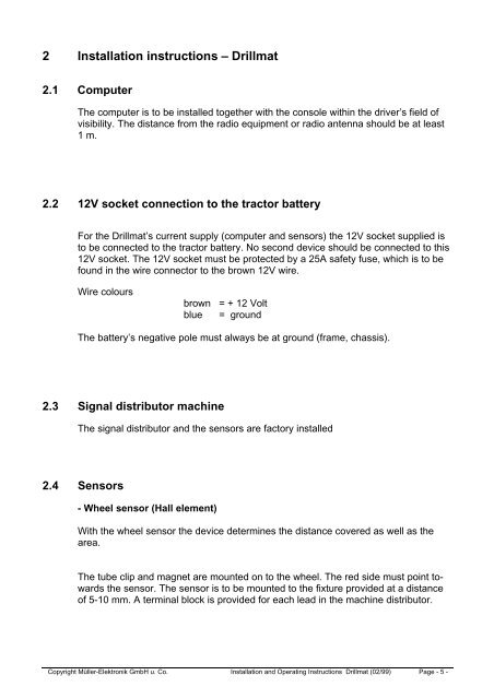
2 <strong>Installation</strong> instructions – <strong>Drillmat</strong><br />
2.1 Computer<br />
The computer is to be installed together with the console within the driver’s field of<br />
visibility. The distance from the radio equipment or radio antenna should be at least<br />
1 m.<br />
2.2 12V socket connection to the tractor battery<br />
For the <strong>Drillmat</strong>’s current supply (computer <strong>and</strong> sensors) the 12V socket supplied is<br />
to be connected to the tractor battery. No second device should be connected to this<br />
12V socket. The 12V socket must be protected by a 25A safety fuse, which is to be<br />
found in the wire connector to the brown 12V wire.<br />
Wire colours<br />
brown = + 12 Volt<br />
blue = ground<br />
The battery’s negative pole must always be at ground (frame, chassis).<br />
2.3 Signal distributor machine<br />
The signal distributor <strong>and</strong> the sensors are factory installed<br />
2.4 Sensors<br />
- Wheel sensor (Hall element)<br />
With the wheel sensor the device determines the distance covered as well as the<br />
area.<br />
The tube clip <strong>and</strong> magnet are mounted on to the wheel. The red side must point towards<br />
the sensor. The sensor is to be mounted to the fixture provided at a distance<br />
of 5-10 mm. A terminal block is provided for each lead in the machine distributor.<br />
Copyright <strong>Müller</strong>-<strong>Elektronik</strong> GmbH u. Co. <strong>Installation</strong> <strong>and</strong> <strong>Operating</strong> <strong>Instructions</strong> <strong>Drillmat</strong> (02/99) Page - 5 -