Cavitron® Plus⢠Ultrasonic Scaler Cavitron® Plus ... - Dentsply
Cavitron® Plus⢠Ultrasonic Scaler Cavitron® Plus ... - Dentsply
Cavitron® Plus⢠Ultrasonic Scaler Cavitron® Plus ... - Dentsply

Create successful ePaper yourself
Turn your PDF publications into a flip-book with our unique Google optimized e-Paper software.
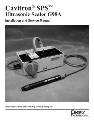
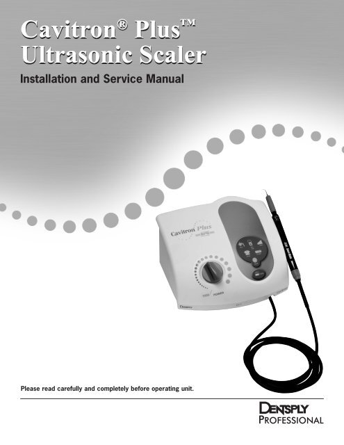
Cavitron ® <strong>Plus</strong> <br />
<strong>Ultrasonic</strong> <strong>Scaler</strong><br />
Installation and Service Manual<br />
Please read carefully and completely before operating unit.
TABLE OF CONTENTS<br />
Introduction . . . . . . . . . . . 3<br />
product overview . . . . . . . . 3<br />
Technical support . . . . . . . . 3<br />
supplies & replacement parts . . 3<br />
indications for use. . . . . . . . 4<br />
contraindications. . . . . . . . 4<br />
warnings. . . . . . . . . . . . . . 4<br />
precautions<br />
4.1 System Precautions. . . . . . . . 4<br />
4.2 Procedural Precautions. . . . . 4-5<br />
INFECTION CONTROL<br />
5.1 General Information . . . . . . . 5<br />
5.2 Water Supply Recommendation . 5<br />
INSTALLATION INSTRUCTIONS<br />
6.1 Water Line Requirements. . . . . 5<br />
6.2 Electrical Requirements. . . . . . 5<br />
6.3 Unpacking the System . . . . . . 6<br />
6.4 System Installation . . . . . . . . 6<br />
6.5 Power Cord Connection . . . . . 6<br />
6.6 Water Supply Line Connection . 6-7<br />
6.7 Foot Control Battery Installation/.<br />
Replacement. . . . . . . . . . . 7<br />
6.8 Foot Control Synchronization. . . 7<br />
CAVITRON® PLUS<br />
SCALER DESCRIPTION<br />
7.1 System Controls . . . . . . . . . 8<br />
7.2 Diagnostic Display Indicators and .<br />
Controls . . . . . . . . . . . . . 9<br />
7.3 Handpiece / Cable . . . . . . . . 10<br />
7.4 Cavitron ® 30K <strong>Ultrasonic</strong><br />
Inserts . . . . . . . . . . . . . .10<br />
7.5 Wireless Foot Control Information .<br />
and Operation . . . . . . . . . .11<br />
7.6 Accessories and User .<br />
Replaceable Parts. . . . . . . . . 11<br />
. . 7.6.1 Accessories . . . . . . .11<br />
. . 7.6.2 User Replaceable Part .<br />
. . .........Kits. . . . . . . . . . . . 11<br />
SYSTEM SETUP, OPERATION<br />
AND TECHNIQUES FOR USE<br />
8.1 Handpiece Setup. . . . . . . . . 11<br />
8.2 Patient Positioning . . . . . . . . 12<br />
8.3 Performing <strong>Ultrasonic</strong> .<br />
Scaling Procedures. . . . . . . . 12<br />
8.4 Patient Comfort Considerations. . 12<br />
SYSTEM CARE<br />
9.1 Daily Maintenance. . . . . . . . 12.<br />
. . Start-up procedures .<br />
. . at the beginning of the day. . . 12.<br />
. . Between patients. . . . . . . . 13.<br />
. . Shut-down procedures at .<br />
. . the end of the day . . . . . . . 13.<br />
9.2 Weekly Maintenance. . . . . . . 13<br />
9.3 Water Line Filter Maintenance . . 13<br />
TROUBLESHOOTING<br />
10.1 Troubleshooting Guide . . . 13-14<br />
10.2 Technical Support and Repairs .14<br />
WARRANTY PERIOD . . . . . . . . 15<br />
SPECIFICATIONS . . . . . . . . . . 15<br />
CLASSIFICATIONS. . . . . . . . . . 15<br />
DISPOSAL OF UNIT. . . . . . . . . 15<br />
QUICK REFERENCE GUIDE. . . 16-17<br />
TROUBLESHOOTING<br />
& ANALYSIS. . . . . . . . . . . 18-23<br />
DISASSEMBLY AND<br />
SERVICE PROCEDURES . . . . . 24-27<br />
WATER FLOW DIAGRAM. . . . . . 28<br />
SERVICE PARTS . . . . . . . . . 29-37
Introduction<br />
Congratulations!<br />
Your decision to add the Cavitron ® <strong>Plus</strong> <strong>Ultrasonic</strong> <strong>Scaler</strong> to<br />
your practice represents a wise investment in good dentistry.<br />
For over four decades, dental professionals have preferred<br />
the clinical benefits and labor-saving advantages inherent in<br />
Cavitron ultrasonic scalers. Clinical studies and independent<br />
research have proven that no other method of supra- and<br />
subgingival calculus removal can surpass the speed,<br />
efficiency, and versatility of ultrasonic scaling.<br />
DENTSPLY Professional is an ISO 13485 registered company.<br />
All DENTSPLY Professional medical devices sold in Europe are<br />
CE marked in conformance with Council Directive 93/42/EEC.<br />
Website: www.professional.dentsply.com<br />
Rx Only: This product is intended for use by qualified dental<br />
professional healthcare providers.<br />
Product Overview<br />
The Cavitron <strong>Plus</strong> <strong>Ultrasonic</strong> <strong>Scaler</strong> is a precision engineered<br />
and manufactured instrument. It contains controls and<br />
components for ultrasonic scaling. The system produces<br />
30,000 strokes per second at the ultrasonic insert’s<br />
working tip that when combined with the cavitational effect of<br />
the coolant lavage creates a synergistic action that<br />
literally “powers away” the heaviest calculus deposits while<br />
providing exceptional operator and patient comfort.<br />
The Cavitron <strong>Plus</strong> <strong>Ultrasonic</strong> <strong>Scaler</strong> is equipped with a<br />
Sustained Performance System (SPS Technology), which<br />
offers a constant balance between scaling efficiency and<br />
patient comfort by maintaining clinical power when the insert<br />
tip encounters tenacious deposits, allowing the clinician to<br />
effectively scale even at a decreased/lower power setting.<br />
The Cavitron <strong>Plus</strong> System has extended the SPS technology<br />
by spreading out the Blue Zone range, providing finer<br />
resolution to the power settings. Advanced features that<br />
make the Cavitron <strong>Plus</strong> a wise investment include a wireless<br />
foot control, illuminated diagnostic display, rinse setting, and<br />
automated purge function.<br />
3<br />
These features combine with established features, such as<br />
the Steri-Mate ® detachable, sterilizable handpiece and swivel<br />
cable with lavage control, low power range, and hands-free<br />
boost mode to provide the ultimate in ultrasonic scaling<br />
experiences for your patients, while still providing the quality<br />
and reliability you’ve come to expect from Cavitron brand<br />
ultrasonic systems.<br />
The Cavitron <strong>Plus</strong> <strong>Ultrasonic</strong> <strong>Scaler</strong> is UL/ULc certified<br />
and approved. The Cavitron <strong>Plus</strong> <strong>Ultrasonic</strong> <strong>Scaler</strong> is<br />
classified by Underwriters Laboratories Inc. with respect to<br />
electric shock, fire, mechanical hazards in accordance with<br />
IEC 60601 Standard. The Cavitron <strong>Plus</strong> <strong>Ultrasonic</strong> <strong>Scaler</strong><br />
complies with Part 15 of the FCC Rules. Operation is subject<br />
to the following two conditions: 1) this device may not cause<br />
harmful interference, and 2) this device must accept any<br />
interference received, including interference that may cause<br />
undesired operation. Cavitron <strong>Plus</strong> base FCC certification/<br />
registration number: FCC ID: TF3-DPD73227323; IC: 4681B-<br />
73227323. Cavitron <strong>Plus</strong> foot control FCC certification/<br />
registration number: FCC ID: TF3-DPD81675; IC: 4681B-<br />
81675. The term IC before the certification/registration<br />
number signifies that the Industry Canada technical<br />
specifications were met.<br />
Technical Support<br />
For technical support and repair assistance in the U.S., call<br />
<strong>Dentsply</strong> Professional Cavitron Care SM Factory Certified<br />
Service at 1-800-989-8826, Monday through Friday, 8:00<br />
A.M. to 5:00 P.M. (Eastern Time). For other areas, contact<br />
your local DENTSPLY Professional Representative.<br />
SupplieS &<br />
Replacement Parts<br />
To order supplies or replacement parts in the U.S., contact<br />
your local DENTSPLY Professional Distributor or call<br />
1-800-989-8826, Monday through Friday, 8:00 A.M. to 5:00<br />
P.M. (Eastern Time). For other areas, contact your<br />
local DENTSPLY Professional Representative.
Section 1:<br />
Indications For Use<br />
• All general supra and subgingival scaling applications<br />
• Periodontal debridement for all types of periodontal<br />
diseases<br />
• Endodontic procedures<br />
Section 2:<br />
Contraindications<br />
• <strong>Ultrasonic</strong> Systems should not be used for restorative<br />
dental procedures involving the condensation of<br />
amalgam.<br />
Section 3: Warnings<br />
• Persons fitted with cardiac pacemakers, defibrillators<br />
and other active implanted medical devices, have been<br />
cautioned that some types of electronic equipment<br />
might interfere with the operation of the device.<br />
Although no instance of interference has ever been<br />
reported to DENTSPLY, we recommend that the<br />
handpiece and cables be kept 6 to 9 inches (15 to 23<br />
cm) away from any device and their leads during use.<br />
There are a variety of pacemakers and other medically<br />
implanted devices on the market. Clinicians should<br />
contact the device manufacturer or the patient’s<br />
physician for specific recommendations. This unit<br />
complies with IEC 60601 Medical Device Standards.<br />
• Failure to follow the recommendations for environmental<br />
operating conditions, including input water temperature,<br />
could result in injury to patients or users.<br />
• The use of High Volume Saliva Evacuation to reduce<br />
the quantity of aerosols released during treatment is<br />
highly recommended.<br />
• It is the responsibility of the Dental Healthcare<br />
Professional to determine the appropriate uses of this<br />
product and to understand the health of each patient,<br />
the dental procedures being undertaken, and industry<br />
and governmental agency recommendations,<br />
requirements, and regulations for safe practice of<br />
dentistry.<br />
• Where asepsis is required or deemed appropriate in<br />
the best professional judgment of the Dental Healthcare<br />
Professional, this product should not be used.<br />
• During boil-water advisories, this product should not<br />
be operated as an open water system (e.g. connected<br />
4<br />
to a public water system). A Dental Healthcare<br />
Professional should disconnect the system from the<br />
central water source. The Cavitron DualSelect system<br />
can be attached to this unit and operated as a closed<br />
system until the advisory is cancelled. When the<br />
advisory is cancelled, flush all incoming waterlines<br />
from the public water system (e.g. faucets, waterlines<br />
and dental equipment) in accordance with the<br />
manufacturer’s instructions for a minimum of 5 minutes.<br />
• Prior to beginning treatment, patients should rinse with<br />
an antimicrobial such as Chlorhexidine Gluconate<br />
0.12%. Rinsing with an antimicrobial reduces the chance<br />
of infection and reduces the number of microorganisms<br />
released in the form of aerosols during treatment.<br />
• Per FCC Part 15.21, changes or modifications not<br />
expressly approved by the party responsible for<br />
compliance could void the user’s authority to operate<br />
this equipment.<br />
Section 4: Precautions<br />
4.1 System Precautions<br />
• Do not place the system on or next to a radiator or<br />
other heat source. Excessive heat may damage the<br />
system’s electronics. Place the system where air is free<br />
to circulate on all sides and beneath it.<br />
• The system is portable, but must be handled with care<br />
when moving.<br />
• Equipment flushing and dental water supply system<br />
maintenance are strongly recommended. See Section 9:<br />
System Care.<br />
• Close manual shut-off valve on the dental office water<br />
supply every night before leaving the office.<br />
• The use of an in-line water filter is recommended.<br />
• Never operate system without fluid flowing through<br />
handpiece.<br />
4.2 Procedural Precautions<br />
• The Cavitron <strong>Plus</strong> unit works with Cavitron inserts as<br />
a system, and was designed and tested to deliver<br />
maximum performance for all currently available Cavitron<br />
and Cavitron Bellissima brand ultrasonic inserts.<br />
Companies that manufacture, repair or modify inserts<br />
carry the sole responsibility for proving the efficacy and<br />
performance of their products when used as a part of<br />
this system. Users are cautioned to understand the<br />
operating limits of their inserts before using in a clinical<br />
setting.
• Like bristles of a toothbrush, ultrasonic insert tips “wear”<br />
with use. Inserts with just 2 mm of wear lose about 50%<br />
of their scaling efficiency. In general, it is recommended<br />
that ultrasonic inserts be discarded and replaced after<br />
one year of use to maintain optimal efficiency and avoid<br />
breakage. A DENTSPLY Professional Insert Efficiency<br />
Indicator is enclosed for your use.<br />
• If excessive wear is noted, or the insert has been bent,<br />
reshaped or otherwise damaged, discard the insert<br />
immediately.<br />
• <strong>Ultrasonic</strong> insert tips that have been bent, damaged, or<br />
reshaped are susceptible to in-use breakage and should<br />
be discarded and replaced immediately.<br />
• Retract the lips, cheeks and tongue to prevent contact<br />
with the insert tip whenever it is placed in the patient’s<br />
mouth.<br />
Section 5:<br />
Infection Control<br />
5.1 General Information<br />
• As with all dental procedures, use universal precautions<br />
(i.e., wear face mask, eyewear, or face shield, gloves<br />
and protective gown).<br />
• For operator and patient safety, carefully practice the<br />
infection control procedures detailed in the Infection<br />
Control Information Booklet accompanying your<br />
System. Additional booklets can be obtained by calling<br />
Customer Service at 1-800-989-8826, Monday through<br />
Friday, 8:00 A.M. to 5:00 P.M. (Eastern Time). For<br />
areas outside the U.S., contact your local DENTSPLY<br />
Professional representative.<br />
• As with high speed handpieces and other dental devices,<br />
the combination of water and ultrasonic vibration from<br />
the Cavitron <strong>Plus</strong> <strong>Scaler</strong> will create aerosols. Following<br />
the procedural guidelines in Section 8 of this manual can<br />
effectively control and minimize aerosol dispersion.<br />
5.2 Water Supply Recommendations<br />
• It is highly recommended that all dental water supply<br />
systems conform to applicable CDC (Centers<br />
for Disease Control and Prevention) and ADA<br />
(American Dental Association) standards, and that all<br />
recommendations be followed in terms of flushing,<br />
chemical flushing, and general infection control<br />
procedures. See Sections 6.1 and 9.<br />
• As a medical device, this product must to be installed<br />
in accordance with applicable local, regional, and<br />
national regulations, including guidelines for water quality<br />
(e.g. drinking water). As an open water system, such<br />
5<br />
regulation may require this device to be connected to<br />
a centralized water control device. The Cavitron ®<br />
DualSelect Dispensing System may be installed to allow<br />
this unit to operate as a closed water system.<br />
Section 6:<br />
Installation Instructions<br />
If the installation of your Cavitron <strong>Plus</strong> System is performed<br />
by someone other than trained DENTSPLY Professional<br />
Distributor personnel, care should be taken to observe the<br />
following requirements and recommendations.<br />
6.1 Water Line Requirements<br />
• A water supply line with user-replaceable filter is<br />
supplied with your system. See Section 9 System Care<br />
for replacement instructions.<br />
• Incoming water supply line pressure to the system must<br />
be 20 psi (138kPa) to 40 psi (275kPa). If your dental<br />
water system’s supply line pressure is above 40 psi,<br />
install a water pressure regulator on the water supply line<br />
to your Cavitron <strong>Plus</strong> <strong>Ultrasonic</strong> Scaling System.<br />
• A manual shut-off valve on the dental water system<br />
supply line should be used so that the water can be<br />
completely shut-off when the office is unoccupied.<br />
• In addition to the water filter supplied, it is recommended<br />
that a filter in the dental water system supply line be<br />
installed so that any particulates in the water supply will<br />
be trapped before reaching the Cavitron system.<br />
• After the above installations are completed on the dental<br />
water supply system, the dental office water line should<br />
be thoroughly flushed prior to connection to the Cavitron<br />
system.<br />
6.2 Electrical Requirements<br />
• Incoming power to the system must be 100 volts AC to<br />
240 volts AC, single phase 50/60 Hz capable of<br />
supplying 1.0 amps.<br />
• The system power should be supplied through the AC<br />
power cord provided with your system.
6.3 Unpacking the System<br />
6.5 Power Cord Connection<br />
• Verify the Main Power ON/OFF switch, located at the<br />
center front underside of the System, is set to the OFF<br />
(O) position before proceeding.<br />
Carefully unpack your Cavitron <strong>Plus</strong> System and verify that<br />
all components and accessories are included:<br />
1. Cavitron ® <strong>Plus</strong> <strong>Scaler</strong> with handpiece<br />
cable assembly with swivel<br />
2. Detachable AC Power Cord<br />
3. Wireless Foot Control<br />
4. “AA” Batteries (4-Pack)<br />
5. Auxiliary Cable for Foot Control<br />
6. Water Line Assembly (Blue) with Filter and<br />
Quick Disconnect<br />
7. Additional Water Line Filter<br />
8. Steri-Mate ® Detachable Sterilizable Handpiece<br />
9. Steri-Mate ® Grip Accessory (not shown)<br />
10. Cavitron ® <strong>Ultrasonic</strong> Inserts (quantity optional)<br />
11. Efficiency Indicator for Cavitron Inserts<br />
12. Literature Packet<br />
• Insert the AC power cord into the power input on the<br />
back of the System.<br />
• Insert the pronged plug into an AC wall outlet.<br />
6.6 Water Supply Line Connection<br />
6.4 System Installation<br />
• The Cavitron <strong>Plus</strong> System is designed to rest on a level<br />
surface. Be sure unit is stable and resting on four feet.<br />
• Placing unit in direct sunlight may discolor plastic<br />
housing.<br />
• The system has been equipped with a wireless foot<br />
control which was factory synchronized to operate with<br />
the system’s base unit. If your office contains more than<br />
one Cavitron <strong>Plus</strong> system, it is recommended that you<br />
mark the foot control and base unit for easy reference as<br />
to which foot control operates with which base unit.<br />
Should resynchronization be necessary, follow the<br />
instructions in Section 6.8.<br />
• Grasp the Water Supply Line (blue hose) by the end<br />
opposite the quick-disconnect and insert it into the water<br />
inlet connector until fully seated.<br />
• Connect the quick disconnect to the dental office water<br />
supply or a Cavitron DualSelect Dispensing System.<br />
• Inspect all connections to make certain there are no<br />
leaks.<br />
6
• To remove the water line from the Cavitron <strong>Plus</strong> System,<br />
turn off the dental office water supply. Disconnect the<br />
water supply line from the dental office water supply. If<br />
a quick-disconnect connector is attached to the end of<br />
the hose, relieve the water pressure by pressing the tip<br />
of the connector in an appropriate container and allow<br />
water to drain. To remove the hose from the system,<br />
push on the outer ring of the system’s water inlet and<br />
gently pull out the water line.<br />
Press ring to release<br />
water supply tube.<br />
6.8 Foot Control Synchronization<br />
The wireless foot control supplied with your system has been<br />
factory synchronized with the base unit. Should a replacement<br />
foot control be necessary, synchronization will be required<br />
prior to system operation. Perform the following steps to<br />
synchronize the foot control with the base unit.<br />
1. Turn the Main Power switch located at the center<br />
front underside of the system to the OFF (O) position.<br />
2. Install a new set of “AA” batteries into the foot control<br />
(See Section 6.7) Leave the battery cover of the<br />
foot control open so the red push button is<br />
accessible.<br />
6.7 Foot Control Battery<br />
Installation/Replacement<br />
• Turn foot control over and using a Philips screwdriver<br />
carefully remove battery cover screw and battery cover.<br />
If applicable, remove used batteries and install two new<br />
“AA” batteries as shown. Do not depress foot control<br />
while installing batteries.<br />
Look for blinking<br />
communications<br />
light.<br />
3. Maintain a distance of no more than 10 feet between<br />
the base unit and foot control during the<br />
synchronization process.<br />
4. Turn the Main Power switch to the ON (I) position<br />
and wait for the Diagnostic Display graphics to light<br />
(refer to Section 7.2).<br />
5. While all graphics are lit, press the Purge button,<br />
located on the Diagnostic Display. The graphics will<br />
begin to blink in a sequential pattern, representing<br />
the synchronization mode. This mode will last 5 to 6<br />
seconds.<br />
• The communication light will blink for approximately<br />
two seconds to indicate the foot control’s ability to<br />
communicate with the unit. If the light does not blink,<br />
check the batteries. If the batteries are good and<br />
the light doesn’t blink, a communications error may<br />
exist. Re-establish communication with Foot Control<br />
Synchronization procedure Section 6.10.<br />
• The remote frequency communication can be bypassed<br />
using the auxillary foot control cable. Refer to Section<br />
10.2 Technical Support and Repair for further action.<br />
• Replace the battery cover and screw and hand tighten<br />
with Philips screwdriver.<br />
• Remove batteries if foot control is to be stored for an<br />
extended period of time.<br />
7<br />
6. During this mode, press the red button located in the<br />
battery compartment of the foot control. This will<br />
complete the synchronization process.<br />
7. Synchronization is successful when all graphics blink<br />
at the same time.<br />
8. To verify proper communication, press the foot<br />
control to the Boost position (foot control fully<br />
pressed – 2 nd position) and ensure the Boost graphic<br />
on base unit lights.<br />
9. Replace battery cover and the screw.
Section 7: Cavitron <strong>Plus</strong> <strong>Scaler</strong> Description<br />
7.1 System Controls<br />
<strong>Ultrasonic</strong> Power Level Control<br />
Turn knob to select the ultrasonic power level for operation. Turning the knob clockwise<br />
increases the distance the insert tip moves (stroke) without changing the frequency; turning<br />
the knob counterclockwise decreases the distance the insert tip moves (stroke) without<br />
changing the frequency.<br />
The Blue Zone is a low-power range for effective subgingival debridement and improved<br />
patient comfort during definitive therapy.<br />
Rinse<br />
Turn ultrasonic power level control knob fully counterclockwise until a “click” is heard. Rinse<br />
mode is for use during an ultrasonic scaling procedure when lavage is desired with minimal<br />
cavitation.<br />
Handpiece<br />
Operates all<br />
Cavitron ® 30K <br />
<strong>Ultrasonic</strong> inserts<br />
and transmits<br />
power and lavage<br />
from the system<br />
to insert.<br />
Diagnostic<br />
Display<br />
See Section<br />
7.2.<br />
Handpiece Holder<br />
Securely holds the<br />
system’s handpiece<br />
(with or without insert)<br />
when the system is<br />
not in use. Also holds<br />
cable connector when<br />
handpiece is not<br />
installed.<br />
Dual Position<br />
Foot Control<br />
See Section 7.5<br />
Main Power ON/OFF Switch<br />
ON/OFF Switch located at the center front underside of the<br />
system.<br />
8
7.2 Diagnostic Display Indicators and Controls<br />
Blue Zone Indicator<br />
Lights when the Power Level Control is positioned<br />
in the Blue Zone of the power scale.<br />
Ideal for effective subgingival debridement and<br />
greater patient comfort.<br />
Rinse Indicator<br />
Lights when the Power<br />
Level Control is turned<br />
fully counterclockwise.<br />
Rinse mode provides<br />
lavage to flush the<br />
procedural area with<br />
negligible tip movement.<br />
Service Indicator<br />
Lights when the system is<br />
not functioning properly.<br />
This diplay has three<br />
distinct modes.<br />
• A fast blink (3 blinks per<br />
second) indicates an<br />
improper set-up.<br />
• A slow blink (1 blink per<br />
second) means the<br />
system is operating out<br />
of factory specifications.<br />
• A steady light indicates<br />
the system is overheating.<br />
Refer to Section 10.1 for<br />
Troubleshooting guidelines.<br />
Boost Indicator<br />
Lights when the<br />
Boost Mode has<br />
been activated.<br />
Low Battery<br />
Indicator<br />
Lights when the foot<br />
control battery power<br />
is approaching end of<br />
life. Replace batteries<br />
as instructed in<br />
Section 6.7.<br />
Power Indicator<br />
Lights (3 Sec. delay)<br />
when the Main Power<br />
ON/OFF Switch is ON<br />
(“I” position).<br />
Purge Control<br />
Lights when the Purge function is activated.<br />
To activate Purge, remove insert from the handpiece,<br />
and press the Purge button. Water will purge through<br />
system for 2 minutes. For optimal efficiency, turn the<br />
handpiece lavage control to maximum water flow. To<br />
deactivate mode during the 2 minute cycle, press<br />
Purge button again or press foot control.<br />
The Purge Control is also used during the Foot Control<br />
Synchronization process. See Section 6.8.<br />
9
7.3 Handpiece / Cable<br />
Steri-Mate ®<br />
Handpiece<br />
Lavage Control<br />
Turn the Lavage Control to select flow rate during<br />
system operation. Clockwise increases flow at insert tip,<br />
counterclockwise decreases flow. The flow rate through the<br />
handpiece also determines the temperature of the lavage.<br />
Lower flow rates produce warmer lavage. Higher flow rates<br />
produce cooler lavage.<br />
If the handpiece becomes warm, increase the flow rate.<br />
With experience, the Dental Healthcare Professional will be<br />
able to determine the best flow rate setting for optimum<br />
operating efficiency and patient comfort.<br />
Swivel Feature<br />
Reduces cable drag as handpiece rotates during procedures.<br />
Steri-Mate Grip Accessory (not shown)<br />
The Steri-Mate Grip provides an ergonomic and comfortable<br />
grasp of the handpiece. The grip is sterilizable and is<br />
available in several different colors as an accessory for your<br />
Steri-Mate Handpiece. See installation instructions provided<br />
with the grip.<br />
7.4 Cavitron 30K <strong>Ultrasonic</strong> Inserts<br />
The many styles of Cavitron and Cavitron Bellissima 30K <strong>Ultrasonic</strong> Inserts are easily interchangeable for various procedures<br />
and applications. See enclosed literature for specific information.<br />
O-Ring<br />
Provides seal for handpiece coolant.<br />
O-ring should be replaced when worn.<br />
Connecting Body<br />
Transfers and amplifies mechanical<br />
motion of stack to insert tip.<br />
Insert Tip<br />
Shape and size of tip<br />
determines access and<br />
adaptation. Preheated Lavage<br />
directed to tip.<br />
Finger Grip<br />
Insert Marking<br />
Manufacturer, Date<br />
(YDDD=Single Digit Year<br />
and Triple Digit Day of<br />
the Year), Frequency,<br />
Type, Tip Lot Number<br />
(if applicable)<br />
Magnetostrictive Stack<br />
Converts energy provided by the handpiece<br />
into mechanical oscillations used to activate<br />
the insert tip.<br />
10
7.5 Wireless Foot Control<br />
Information and Operation<br />
The foot control is a two-positioned momentary switch.<br />
The first position activates both the ultrasonic energy and<br />
lavage at the insert tip. The second position activates the<br />
Boost Mode. The Boost Mode (fully depressed foot control)<br />
increases the ultrasonic power level for quick, efficient<br />
removal of tenacious deposits without touching the system<br />
base. To deactivate Boost Mode, release foot control to first<br />
position.<br />
Section 8: System Setup,<br />
Operation and Techniques<br />
for Use<br />
8.1 Handpiece Setup<br />
• Pressing anywhere on the top of the foot control<br />
activates the system.<br />
NON-DEPRESSED<br />
DEPRESSED<br />
1st POSITION<br />
DEPRESSED<br />
2nd POSITION<br />
7.6 Accessories and User<br />
Replaceable Part<br />
7.6.1 Accessories<br />
1. AC Power Cord<br />
2. Dual Position Foot Control (Wireless)<br />
3. Auxiliary Foot Control Cable<br />
4. Cavitron 30K <strong>Ultrasonic</strong> Inserts<br />
5. Cavitron DualSelect Dispensing system<br />
6. Cavitron Steri-Mate Sterilizable Handpiece<br />
7. Cavitron Steri-Mate Grip (Available in a variety<br />
of colors)<br />
• Connect the Handpiece to the Cable Assembly by<br />
aligning the electrical connections. If Cable Assembly<br />
does not seat into the handpiece, gently rotate the<br />
handpiece until contacts align, then fully insert handpiece.<br />
• Hold empty handpiece in an upright position over a<br />
sink or drain. Activate the Foot Control until water exits<br />
to bleed any air bubbles that might be trapped inside the<br />
handpiece.<br />
• Lubricate the O-ring on the insert with water before<br />
placing it into the handpiece. Fully seat insert with a<br />
gentle push-twist motion. DO NOT FORCE.<br />
7.6.2 User Replaceable Part Kits<br />
1. Cavitron Insert Replacement O-ring 12/Packs<br />
PN: 62351 (black) for plastic and Bellissima inserts<br />
PN: 62605 (green) for metal grips and prophy<br />
2. Steri-Mate Handpiece Cable O-ring, PN: 79357<br />
3. Lavage (Water) Filter, 10/Pack, PN: 90158<br />
For detailed information, contact your local DENTSPLY<br />
Professional Representative or authorized DENTSPLY<br />
Professional Distributor.<br />
• Turn the Lavage Control to select flow rate during<br />
system operation. Clockwise increases flow at insert tip,<br />
counterclockwise decreases flow. The flow rate through<br />
the handpiece also determines the temperature of<br />
the lavage. Lower flow rates produce warmer<br />
lavage. Higher flow rates produce cooler lavage. If<br />
the handpiece becomes warm, increase the flow rate.<br />
With experience the Dental Healthcare Professional will<br />
be able to determine the best flow rate setting for<br />
optimum operating efficiency and patient comfort.<br />
11
8.2 Patient Positioning<br />
For optimal access to both the upper and lower arches, the<br />
backrest of the chair should be adjusted as for other dental<br />
procedures. This assures patient comfort and clinician<br />
visibility.<br />
Have the patient turn his/her head to the right or left. Also<br />
position chin up or down depending upon the quadrant and<br />
surface being treated. Evacuate irrigant using either a saliva<br />
ejector or High Volume Evacuator (HVE).<br />
8.3 Performing <strong>Ultrasonic</strong><br />
Scaling Procedures<br />
Note: Refer to the Infection Control Information<br />
booklet supplied with your system and Section 9 of<br />
this manual for general procedures to be followed<br />
at the beginning of each day and between patients.<br />
• The edges of Cavitron <strong>Ultrasonic</strong> Inserts are intentionally<br />
rounded so there is minimal danger of tissue laceration<br />
with proper ultrasonic scaling technique. Whenever the<br />
insert tip is placed in the patient’s mouth, the lips,<br />
cheek and tongue should be retracted to prevent<br />
accidental (prolonged) contact with the activated tip.<br />
• Turn Power Level Control to select ultrasonic power level<br />
for operation. Clockwise increases system power.<br />
Power level will increase throughout the full range of the<br />
control. Hold the handpiece over a sink or drain.<br />
Press the foot control to activate the system. Check<br />
spray to verify fluid is reaching the working end of the<br />
insert tip. Adjust the Lavage Control to ensure adequate<br />
flow for the selected power setting. Greater flow settings<br />
provide cooler irrigation.<br />
• It may be necessary to adjust lavage with the system in<br />
“Boost” mode (Foot Control fully depressed) so adequate<br />
fluid will be available to cool tip to tooth interface.<br />
• In general, it is suggested that a “feather-light-touch” be<br />
used for ultrasonic scaling. The motion of the activated<br />
tip and acoustic effects of the irrigating fluid, in most<br />
cases, are adequate to remove even the most tenacious<br />
calculus.<br />
• Periodically check the Cavitron <strong>Ultrasonic</strong> Insert for wear<br />
with the Cavitron Insert Efficiency Indicator.<br />
• The use of a saliva ejector or High Volume Evacuator<br />
(HVE) is recommended during all procedures.<br />
• Set the system’s Power Level Control to the lowest<br />
efficient power setting for the application and the<br />
selected insert.<br />
8.4 Patient Comfort Considerations<br />
Reasons for sensitivity<br />
• Incorrect tip placement. The point should never be<br />
directed toward tooth root surfaces.<br />
• Not keeping tip in motion on tooth. Do not allow the<br />
insert to remain in a static position on any one area of<br />
the tooth. Change the insert’s path of motion.<br />
• Applying excessive pressure. Use a very light grasp<br />
and pressure, with a soft tissue fulcrum whenever<br />
possible, especially on exposed cementum.<br />
• If sensitivity persists, decrease power setting and/or<br />
move from the sensitive tooth to another and then return.<br />
Section 9: System Care<br />
It is recommended that you perform the following maintenance<br />
procedures to help maximize water quality and to be in<br />
compliance with CDC guidelines for infection control.<br />
9.1 Daily Maintenance<br />
Start-Up Procedures at the<br />
beginning of the day:<br />
1. Open the manual shut-off valve on the dental office<br />
water supply system.<br />
2. Install a sterilized Steri-Mate handpiece on the<br />
handpiece cable.<br />
3. Turn Main Power Switch to the ON (I) position. Verify<br />
the ON/OFF indicator light is lit.<br />
4. Set the Power Level Control to the minimum setting<br />
(not rinse).<br />
5. Set the Lavage Control on the handpiece cable to<br />
maximum.<br />
6. Hold the Handpiece (without an insert installed)<br />
upright over a sink or drain. Activate the Purge<br />
Control button.<br />
• The Purge button will light for two minutes<br />
indicating activation of the purge function.<br />
• If the Purge button is activated with an insert<br />
present in the handpiece, the button will blink for<br />
3 seconds and disable. Remove the insert from<br />
the handpiece and press the Purge button again.<br />
• The Purge function can be interrupted at any time<br />
by pressing the Purge button again or by<br />
pressing the foot control.<br />
7. After completing the purge cycle, place a sterilized<br />
insert into the Handpiece and set the <strong>Ultrasonic</strong><br />
Power Level Control and Lavage Control to your<br />
preferred operating position.<br />
12
Between Patients:<br />
1. Remove ultrasonic insert used. Clean and sterilize<br />
the ultrasonic insert(s) following the procedures<br />
outlined in the Cavitron <strong>Ultrasonic</strong> Insert Infection<br />
Control Direction for Use enclosed with every insert.<br />
2. Hold the handpiece over a sink or drain and activate<br />
Purge function as described in Step 6 of Start-Up<br />
Procedures.<br />
3. After the purge cycle is complete, turn the system<br />
OFF, (O) position.<br />
4. Remove the Steri-Mate handpiece. Clean and sterilize<br />
the handpiece following the procedure outlined in the<br />
booklet enclosed with your unit.<br />
5. Disinfect the surfaces of the cabinet, Power Cord,<br />
Handpiece Cable, Water Supply Line, Foot Control<br />
and Auxillary Cable (if applicable) by applying an<br />
approved non-immersion type disinfectant solution*<br />
carefully following the instructions provided by the<br />
disinfectant solution manufacturer. To clean System,<br />
generously spray disinfectant solution on a clean<br />
towel and wipe all surfaces. Discard used towel. Dry<br />
with a clean cloth. To disinfect system, generously<br />
spray disinfectant on a clean towel and wipe all<br />
surfaces. Allow disinfectant solution to air dry. Never<br />
spray disinfectant solution directly on the system.<br />
6. Inspect the handpiece cable for any breaks or tears.<br />
7. If using a closed water supply or DualSelect<br />
Dispensing system, check for adequate fluid volume<br />
for the next patient.<br />
8. When ready for use, place a sterilized Steri-Mate<br />
handpiece on the handpiece cable and a sterilized<br />
insert into the handpiece and adjust system controls<br />
to preferred operator positions.<br />
Shut-Down Procedures at the<br />
end of the day:<br />
Follow the “Between Patients” maintenance procedures,<br />
Steps 1 through 6. In addition, it is recommended to close<br />
the manual shut-off valve on the dental water supply system.<br />
*NOTE: Water-based disinfection solutions are<br />
preferred. Some alcohol-based disinfectant<br />
solutions may be harmful and may discolor<br />
plastic materials.<br />
9.2 Weekly Maintenance<br />
It is strongly recommended that this system be disinfected<br />
by chemically flushing the waterlines with a 1:10 Sodium<br />
Hypochlorite solution (NaOCl) at the end of each week.<br />
This can be accomplished by connecting this device to the<br />
Cavitron DualSelect Dispensing System or a number of other<br />
devices available from your local distributors. Where this<br />
device is connected to the Cavitron DualSelect Dispensing<br />
System, please follow the DualSelect system’s Directions for<br />
13<br />
Use manual. If connected to another device, please follow<br />
those directions for use, keeping in mind that a chemical<br />
flush should be performed at maximum water flow for at least<br />
30 seconds. The system should be left undisturbed for 10<br />
minutes but no more than 30 minutes to allow the sodium<br />
hypochlorite solution to soak in the lines. As a suggestion, it<br />
is recommended that a sign be placed on the system stating<br />
that the SYSTEM IS BEING DISINFECTED WITH A STRONG<br />
DISINFECTANT AND SHOULD NOT BE USED. When ready,<br />
flush system with clean water for at least 30 seconds or<br />
until sodium hypochlorite odor disappears. ALL CHEMICALS<br />
MUST BE FLUSHED FROM THE SYSTEM BEFORE IT IS READY<br />
FOR PATIENT USE.<br />
9.3 Water Line Filter Maintenance<br />
When the water line filter becomes discolored, the filter<br />
should be replaced to prevent reduced water flow to the<br />
Cavitron <strong>Plus</strong> <strong>Ultrasonic</strong> <strong>Scaler</strong>. A 10-pack of replacement<br />
filters is available by ordering Part Number 90158 from your<br />
local authorized DENTSPLY Distributor.<br />
1. Verify system is turned OFF.<br />
2. Disconnect the water supply hose from the water<br />
source. If a quick-disconnect connector is attached<br />
to the end of the hose, relieve the water pressure by<br />
pressing the tip of the connector in an appropriate<br />
container to drain the water.<br />
3. Grasp the fitting on either side of the filter disk and<br />
twist counterclockwise. Remove the filter section<br />
from either side of the water hose.<br />
4. Install the replacement filter onto the water hose<br />
fittings. The filter should be positioned to match up<br />
with the correct hose fitting.<br />
5. Hand tighten the two hose fittings in a clockwise<br />
direction. Reconnect the water supply hose, operate<br />
the unit to bleed the air and test for leaks.<br />
Section 10:<br />
Troubleshooting<br />
Although service and repair of the Cavitron <strong>Plus</strong> <strong>Ultrasonic</strong><br />
<strong>Scaler</strong> should be performed by DENTSPLY personnel, the<br />
following are some basic trouble shooting procedures that<br />
will help avoid unnecessary service calls. Generally, check all<br />
lines and connections to and from the System, a loose plug<br />
or connection will often create problems. Check the settings<br />
on the System’s controls.<br />
10.1 Troubleshooting Guide<br />
Symptom:<br />
System will not operate: No Power ON indicator<br />
1. Check that the Main Power Switch is in the ON (l)<br />
position, and that the detachable Power Cord is fully<br />
seated in the receptacle on back of System.
2. Check that the system’s power cord plug is fully seated<br />
in an approved AC wall outlet.<br />
3. Check that the wall outlet is functional.<br />
Symptom:<br />
System will not operate: Power ON Indicator is<br />
illuminated<br />
1. If the office has more than one foot control, test each<br />
to ensure that the proper foot control is being used.<br />
With a handpiece and insert installed, depress the<br />
foot control to the first position. The system should<br />
dispense water. If none of the foot controls operate<br />
the system, continue to the next step.<br />
2. Resynchronize one foot control to the system (see<br />
Section 6.8 Foot Control Synchronization).<br />
Symptom:<br />
System operates: No water flow to insert tip<br />
1. Assure that handpiece lavage control is properly<br />
adjusted.<br />
2. Check for clogged insert.<br />
3. Check that dental office water supply valves are open.<br />
4. If the system is connected to DualSelect Dispensing<br />
System, check that fluid level in the selected bottle is<br />
sufficient. Make sure valves are open when using<br />
external water source.<br />
5. Check that the water line filter is clean. Replace filter<br />
if needed.<br />
Symptom:<br />
System operates: No insert cavitation<br />
1. Check that the Power Level Control is not in Rinse<br />
Mode.<br />
2. Check the insert for damage and that it is properly<br />
installed in the handpiece.<br />
3. Check that the handpiece is properly installed to the<br />
cable assembly.<br />
4. If Steri-Mate grip is used on the handpiece, verify that<br />
the grip is flush with the hard plastic of the insert port.<br />
5. Turn the system’s Main Power Switch to the OFF (0)<br />
position. Wait 5 seconds and turn the system back ON.<br />
6. If problem still exists, replace both “AA” batteries in<br />
foot control with new “AA” batteries (Refer to Section<br />
6.7) or connect auxiliary foot control cable.<br />
Symptom:<br />
System operates: Purge Mode will not function<br />
– icon flashing<br />
1. Check that there is no insert in the handpiece.<br />
2. Check that handpiece is properly installed to the cable<br />
assembly.<br />
Symptom:<br />
System operates: Service Indicator blinking<br />
• Slow Blinking (1 blink per second)<br />
The system is not operating within factory<br />
specifications.<br />
1. Remove insert.<br />
2. Turn Main Power Switch OFF, (O) position. Wait five<br />
seconds. Turn unit ON, (I) position.<br />
3. Operate Purge function.<br />
4. If service indicator still blinks, refer to Section 10.2<br />
Technical Support and Repairs to have unit<br />
serviced as soon as possible.<br />
• Fast Blinking (3 blinks per second)<br />
– Indicates improper set-up<br />
1. If insert is in the handpiece, remove. Verify the<br />
handpiece is properly seated and depress the foot<br />
control for 2 seconds. If blinking stops, the system<br />
is ready for use. If blinking remains, continue to the<br />
next step.<br />
2. Attach a NEW handpiece and depress foot control<br />
for 2 seconds. If blinking stops, the system is<br />
ready for use. Discard the old handpiece or return if<br />
within warranty. If blinking remains, continue to the<br />
next step.<br />
3. Install and fully seat an insert into handpiece.<br />
Depress foot control for 2 seconds. If blinking<br />
stops, unit is ready for use. If blinking remains,<br />
continue to the next step.<br />
4. Install and fully seat a NEW insert in handpiece and<br />
depress foot control for 2 seconds. If blinking<br />
stops, system is ready for use. Discard old insert<br />
or return if within warranty. If blinking remains,<br />
refer to Section 10.2 Technical Support and<br />
Repairs to have unit serviced as soon as possible.<br />
Symptom:<br />
System operates: Service Indicator illuminated<br />
1. Ensure that the base unit has adequate ventilation and<br />
is not near a heat source (i.e. radiator, heat lamp,<br />
sunlight or other heat producing operatory equipment).<br />
2. Turn Main Power Switch to the OFF (O) position. Allow<br />
system to cool for 10 minutes and turn system ON, (I)<br />
position. Verify light is not illuminated.<br />
3. If light is still illuminated, refer to Section 10.2<br />
Technical Support and Repairs to have unit serviced as<br />
soon as possible.<br />
10.2 Technical Support and Repairs<br />
For technical support and repair assistance call DENTSPLY<br />
Professional Cavitron Care SM Factory Certified Service at 1-<br />
800-989-8826 Monday through Friday, 8:00 A.M. to 5:00<br />
P.M. (Eastern Time). For areas outside the U.S., contact your<br />
local DENTSPLY Professional representative.<br />
14
Section 11:<br />
Warranty Period<br />
The Cavitron <strong>Plus</strong> <strong>Ultrasonic</strong> <strong>Scaler</strong> is warranted for TWO YEARS from date of purchase. The Steri-Mate Handpiece enclosed<br />
with your system is warranted for SIX MONTHS from date of purchase. Refer to the Warranty Statement Sheet furnished with<br />
your system for full Warranty Statement and Terms.<br />
Section 12: Specifications<br />
Electrical Voltage<br />
Current<br />
Phase<br />
Frequency<br />
Water Pressure<br />
Water Flow Rate<br />
Weight<br />
Dimensions<br />
Foot Control<br />
Continuous (100-240 VAC)<br />
1.0 Amperes, Maximum<br />
Single<br />
50/60 Hertz<br />
20 to 40 psig (138 to 275 kPa)<br />
Minimum Setting (CCW) < 15 ml/min<br />
Maximum Setting (CW) > 55 ml/min<br />
3.3 lbs (1.5 Kg)<br />
Height: 5 in (12,7 cm)<br />
Width: 9.5 in (24,13 cm)<br />
Depth: 8 in (20,32 cm)<br />
Handpiece Cable length: 6.5 ft. (2.0 M)<br />
Auxillary Foot Control Cable length: 8ft. (2.4 M)<br />
Water Supply Line length: 8 ft. (2.4 M)<br />
Protection Class IPX1. Not for operating theatres.<br />
Remote Communication Frequency: 2405 to 2480 MHz<br />
Power: < 1mW<br />
Channels: 16<br />
Operating Environment<br />
Transport and Storage Conditions<br />
Section 13: Classifications<br />
Temperature: 15 to 40 Deg. Celsius (59 to 104 Deg. Fahrenheit)<br />
Relative Humidity: 30% to 75% (non-condensing)<br />
Temperature: -40 to 70 Deg. Celsius (-40 to 158 Deg. Fahrenheit)<br />
Relative Humidity: 10% to 100% (non-condensing)<br />
Atmospheric Pressure: 500 to 1060 hPa<br />
• Type of protection against electric shock: Class 1<br />
• Degree of protection against electric shock:<br />
Type B<br />
• Degree of protection against the harmful ingress of water: Ordinary<br />
• Mode of operation:<br />
Continuous<br />
• Degree of safety of application in the presence of a flammable<br />
anaesthetic mixture with air or with oxygen or nitrous oxide: Equipment not suitable for use in the presence of<br />
flammable anaesthetic or oxygen. IIA (rule 9)<br />
(ISO/IEC 60601)<br />
Section 14: Disposal of Unit<br />
• Accordance with local and state laws.<br />
15
Cavitron <strong>Plus</strong> <strong>Ultrasonic</strong> <strong>Scaler</strong><br />
Quick Reference Guide<br />
Diagnostic Display<br />
ON/OFF<br />
Illuminates when the Main Power On/Off switch is in the “ON”<br />
position.<br />
BLUE ZONE<br />
Illuminates when the ultrasonic power control is positioned in the Blue Zone<br />
of the power scale. The Blue Zone extended low-power range is effective for<br />
subgingival debridement and greater patient comfort during definitive therapy.<br />
RINSE<br />
Illuminates when the ultrasonic power level control is turned fully<br />
counterclockwise. With an insert in the handpiece, activate the Foot<br />
Control and lavage will occur with negligible tip movement.<br />
Boost<br />
Illuminates when the Boost Mode is activated by the Foot Control. To<br />
activate, fully depress Foot Control to the second position. To deactivate<br />
Boost Mode, release Foot Control to first position.<br />
PURGE button<br />
Illuminates when the Purge function is activated. To activate Purge, remove insert from the handpiece,<br />
press the Purge button on the Diagnostic Display and water will purge through system lines for two<br />
minutes. For optimal efficiency, turn the Handpiece Lavage Control to maximum water flow. To<br />
deactivate during the two minute cycle, press Purge button again or press Foot Control.<br />
SERVICE<br />
Power Control<br />
Lights when the system is not functioning properly. This display has three distinct modes:<br />
• Slow blink (1 blink per second) means the system is not operating within factory specifications.<br />
• Fast blink (3 blinks per second) indicates an improper set-up.<br />
• Steady light indicates the system is overheating.<br />
Refer to Troubleshooting guidelines on reverse side.<br />
LOW BATTERY<br />
Illuminates when the Foot Control battery power is approaching end of life. Replace batteries as<br />
instructed in the Directions for Use.<br />
POWER LEVEL CONTROL<br />
Turn knob to select ultrasonic power level for operation. Turning the knob clockwise increases the<br />
distance the insert tip moves (stroke) without changing the frequency; turning the knob counterclockwise<br />
decreases the distance the insert tip moves (stroke) without changing the frequency.<br />
RINSE<br />
Rinse mode is used during an ultrasonic scaling procedure when lavage is required to flush the procedural<br />
area. To activate, turn Power Level Control fully counterclockwise until a “click” is heard.<br />
BLUE ZONE<br />
Provides an extended low-power range for effective subgingival debridement and greater patient comfort<br />
during definitive therapy.<br />
16<br />
PURGE<br />
.
QUICK REFERENCE GUIDE TROUBLESHOOTING<br />
SYMPTOM<br />
System will<br />
not operate:<br />
No Power ON<br />
Indicator<br />
ACTION TAKEN<br />
1. Check that the Main Power Switch is in the ON (I) position, and that the detachable power cord<br />
is fully seated in the receptacle on back of system.<br />
2. Check that the system’s power cord plug is fully seated in an appropriate AC wall outlet.<br />
3. Check that the wall outlet is functional.<br />
System will<br />
not operate:<br />
Power ON<br />
Indicator is<br />
illuminated<br />
System operates:<br />
No water flow to<br />
insert tip<br />
System operates:<br />
No insert<br />
cavitation<br />
Service<br />
indicator<br />
blinking<br />
System operates:<br />
Service indicator<br />
illuminated<br />
System operates:<br />
Purge mode will<br />
not function --<br />
icon flashing<br />
1. If the office has more than one foot control, test each to ensure that the proper foot control is<br />
being used. With a handpiece and insert installed, depress the foot control to the first position.<br />
The system should dispense water. If none of the foot controls operate the system, continue to<br />
the next step.<br />
2. Resynchronize one foot control to the system (see Directions for Use Section 6.8 Foot Control<br />
Synchronization).<br />
1. Assure that handpiece lavage control is properly adjusted.<br />
2. Check for clogged insert; Replace insert if necessary.<br />
3. Check that dental office water supply valves are open.<br />
4. If the system is connected to DualSelect Dispensing System, check that fluid level in the selected<br />
bottle is sufficient. Make sure valves are open when using external water source.<br />
5. Check that the water line filter is clean; Replace filter, if needed.<br />
1. Check that the Power Level Control is not in Rinse Mode.<br />
2. Check the insert for damage and that it is properly installed in the Handpiece.<br />
3. Check that the handpiece is properly installed to the cable assembly.<br />
4. Verify that the handpiece’s soft grip is flush with the hard plastic of the insert port. (Skip this step<br />
if not using Soft Grip Accessory)<br />
5. Turn the system’s Main Power Switch OFF, (O) position. Wait 5 seconds and turn the system back ON.<br />
6. If problem still exists, replace both “AA” batteries in foot control with new “AA” batteries, or<br />
connect Auxiliary Foot Control Cable.<br />
1. Slow blinking (1 blink per second) - The system is not operating within factory specifications.<br />
A. Remove insert.<br />
B. Turn Main Power Switch OFF, (O) position. Wait five seconds. Turn switch ON, (I) position.<br />
C. Operate Purge function.<br />
D. If service indicator still blinks, refer to Technical Support and Repairs to have unit serviced<br />
as soon as possible.<br />
2. Fast blinking (3 blinks per second) – Indicates improper set-up<br />
A. If insert is in the handpiece, remove. Verify the handpiece is properly seated and depress<br />
the foot control for 2 seconds. If blinking stops, the system is ready for use. If blinking<br />
remains, continue to the next step.<br />
B. Attach a NEW handpiece and depress foot control for 2 seconds. If blinking stops, the<br />
system is ready for use. Discard the old handpiece or return if within warranty. If blinking<br />
remains, continue to the next step.<br />
C. Install and fully seat an insert into handpiece. Depress foot control for 2 seconds. If<br />
blinking stops, unit is ready for operation. If blinking remains, continue to the next step.<br />
D. IInstall and fully seat a NEW insert in handpiece and depress foot control for 2 seconds. If<br />
blinking stops, system is ready for use. Discard old insert or return if within warranty.<br />
If blinking remains, refer to Technical Support<br />
1. Ensure that the base unit has adequate ventilation and is not near a heat source (i.e. radiator,<br />
heat lamp, sunlight or other heat producing operatory equipment).<br />
2. Turn Main Power Switch OFF, (O) position. Allow system to cool for 10 minutes and turn system<br />
ON, (I) position. Verify light is not illuminated.<br />
3. If light is still illuminated, refer to Technical Support and Repairs to have unit serviced as soon as<br />
possible<br />
1. Check that there is no insert in the handpiece.<br />
2. Check that handpiece is properly installed to the cable assembly.<br />
17
Section 16: Cavitron ® <strong>Plus</strong> Troubleshooting and Analysis<br />
This troubleshooting section is meant for use by qualified Cavitron ® Service Technicians.<br />
SYMPTOMS CAUSES CORRECTIVE MEASURES<br />
Cavitron ® <strong>Plus</strong> scaler does<br />
not power up: pilot light does<br />
not illuminate.<br />
1. Faulty wall outlet.<br />
2. Damaged power cord.<br />
1. Check wall outlet and if faulty take necessary<br />
corrective measures.<br />
2. Replace the power cord.<br />
3. Fuse F3 and/or F4 blown.<br />
4. Damaged On/Off switch.<br />
3. Replace internal fuses F3 and F4 with specified<br />
fuses.<br />
4. Replace the On/Off switch.<br />
Slo-Blo Fuses good. No power<br />
to circuitry.<br />
Slo-Blo Fuse F3 and/or F4<br />
Failed.<br />
1. Unit is installed in a confined area<br />
(such as a cabinet), or is too<br />
close to a heat source to insure<br />
proper air circulation around unit.<br />
1. Short in Power supply assembly.<br />
2. Short in Power Drive PC Board<br />
assembly.<br />
1. Provide adequate air circulation around unit.<br />
1. Replace the Power Supply assembly.<br />
2. Replace the Power Drive PC Board assembly.<br />
Low insert scaling power or<br />
insert stops vibrating when<br />
contacting tooth surface.<br />
1. Insert malfunction.<br />
2. Insert is not pushed in far enough<br />
for automatic pick-up.<br />
3. Unit improperly calibrated.<br />
1. Test with another Cavitron ® insert. If test insert<br />
works properly, discard the original insert.<br />
2. a. Check if insert is fully seated in the handpiece.<br />
b. If a handpiece soft grip is being used, verify<br />
that the grip is flush with the hard plastic of the<br />
insert port. Refer to the Installation<br />
Instructions provided with the soft grip for<br />
correct installation.<br />
3. a. Return scaler to DENTSPLY ® for factory<br />
certified service.<br />
b. Refer to DENTSPLY ® Professional Division-<br />
Product Service SOP PS-153.<br />
18
Cavitron ® <strong>Plus</strong> Troubleshooting and Analysis, continued<br />
This troubleshooting section is meant for use by qualified Cavitron ® Service Technicians.<br />
SYMPTOMS CAUSES CORRECTIVE MEASURES<br />
Intermittent scaling power or no<br />
scaling power.<br />
1. Insert malfunction.<br />
1. Test with another Cavitron ® insert. If test insert<br />
works properly, discard the original insert.<br />
2. Insert is not pushed in far<br />
enough for automatic pick-up.<br />
3. Malfunction in Steri-Mate<br />
Handpiece.<br />
4. Bent or missing electrical pin in<br />
Steri-Mate Handpiece.<br />
5. Open or intermittent wires in<br />
handpiece cable assembly.<br />
2. a. Check if insert is fully seated in the handpiece.<br />
b. If a handpiece soft grip is being used, verify<br />
that the grip is flush with the hard plastic of the<br />
insert port. Refer to the Installation<br />
Instructions provided with the soft grip for<br />
correct installation.<br />
3. Replace Steri-Mate Handpiece.<br />
4. Replace Steri-Mate Handpiece.<br />
5. Install a working Steri-Mate Handpiece on the<br />
cable. Unplug the Handpiece cable connector at J3<br />
of the Power Drive PC Board and check the<br />
continuity of the wires.<br />
a. Connect the ohmmeter between RED-GRN wire<br />
terminals. Flex the handpiece cable and check<br />
for intermittent readings. If the ohmmeter<br />
reading is not consistent or it is indicating an<br />
open circuit, the handpiece cable assembly is<br />
likely to be damaged and should be replaced.<br />
b. Connect the ohmmeter between WHT-GRN wire<br />
terminals and repeat the procedure above.<br />
6. Loose wiring or defective solder<br />
joint in the unit wiring<br />
7. Foot Control battery weak.<br />
6. Troubleshoot the unit wiring and connectors.<br />
7. a. Check information center for Low Battery<br />
light indication. Replace battery as needed.<br />
b. Connect an auxiliary Foot Control cable<br />
between the Foot Control and the unit. The<br />
unit can be operated with the cable until the<br />
battery is replaced.<br />
8. Foot Control not synchronized<br />
to the unit.<br />
8. a. Follow Directions for Use & Service Manual<br />
instructions for Foot Control synchronizing.<br />
b. Connect the auxiliary Foot Control cable<br />
between the Foot Control and unit. Unit can be<br />
operated with the cable until the Foot Control is<br />
synchronized.<br />
19
Cavitron ® <strong>Plus</strong> Troubleshooting and Analysis, continued<br />
This troubleshooting section is meant for use by qualified Cavitron ® Service Technicians.<br />
SYMPTOMS CAUSES CORRECTIVE MEASURES<br />
Intermittent scaling power or no<br />
scaling power.<br />
(Continued)<br />
9. Foot Control malfunction. 9. Connect the auxiliary Foot Control cable between<br />
the Foot Control and the unit. If the unit will not<br />
operate with the auxiliary cable connected, replace<br />
the Foot Control. Follow the Directions for Use<br />
and Service Manual instructions for Foot Control<br />
synchronizing.<br />
Handpiece heats up.<br />
1. Insufficient water to cool<br />
handpiece.<br />
2. Air trapped in the handpiece.<br />
3. Insert water passageway clogged.<br />
4. Handpiece cable not supported<br />
during procedure.<br />
5. Worn insert being used.<br />
1. Increase the setting on the handpiece lavage<br />
control until handpiece runs cool.<br />
2. When the inserts are changed, hold the handpiece<br />
in an upright position until the trapped air is<br />
removed and the water flows properly.<br />
3. Replace the Cavitron ® insert and check operation.<br />
4. Loop handpiece cable around arm or support with<br />
finger to prevent water restriction.<br />
5. Replace with a new Cavitron ® insert. Worn inserts<br />
require higher power settings producing more<br />
heat.<br />
Insert vibrates but no water or<br />
insufficient water flows from the<br />
handpiece.<br />
1. Low incoming dental office water<br />
pressure.<br />
2. Water filter clogged.<br />
3. Handpiece cable water tubing and<br />
wires twisted.<br />
4. Damaged handpiece cable Flow<br />
Control.<br />
5. Obstruction or mineral deposits in<br />
the water system in the unit.<br />
1. Measure water pressure at dental office.<br />
Adjust incoming source water pressure to<br />
specification. Water pressure should be 20-40<br />
psi.<br />
2. Replace the water filter when discolored or<br />
restriction occurs.<br />
3. Remove restriction if possible or replace<br />
handpiece cable assembly.<br />
4. Replace handpiece cable assembly.<br />
5. a. Remove the insert and turn the water valve<br />
full open. Observe the water flow. If the flow<br />
is good then the obstruction is in the insert.<br />
b. If the obstruction is not in the insert, then<br />
remove the handpiece water line at solenoid<br />
and check the water flow. If flow is good, then<br />
the obstruction is in handpiece supply line.<br />
20
Cavitron ® <strong>Plus</strong> Troubleshooting and Analysis, continued<br />
This troubleshooting section is meant for use by qualified Cavitron ® Service Technicians.<br />
SYMPTOMS CAUSES CORRECTIVE MEASURES<br />
No water flow from handpiece<br />
with no insert installed.<br />
1. High dental office water pressure. 1. Install a water pressure regulator on the main<br />
water supply line and reduce the pressure to<br />
20-40 psi.<br />
Water spray from insert is not<br />
properly covering the operating<br />
area of the activated tip.<br />
1. Improper water flow adjustment.<br />
2. P-style insert water tube<br />
incorrectly aimed.<br />
3. Insert is partially clogged.<br />
1. Refer to “Instructions For Using DENTSPLY ®<br />
Cavitron ® <strong>Plus</strong> <strong>Ultrasonic</strong> Dental Unit” for<br />
instructions on water flow adjustment.<br />
2. Use small smooth pliers, reposition the water tube<br />
and direct the spray at the back of the insert tip.<br />
3. Replace the insert.<br />
Water drips from the handpiece<br />
when not operating.<br />
Water leak from the handpiece<br />
while in operation.<br />
1. Water solenoid valve leaking due<br />
to trapped debris.<br />
1. O-ring worn on insert.<br />
2. Water leak in plastic water line<br />
at handpiece or inside the<br />
SteriMate Handpiece.<br />
1. Try plugging the water supply hose into an air<br />
source to blow out the dirt. If the leak persists,<br />
replace the regulator/solenoid assembly. Be sure<br />
the external hose filter is installed.<br />
1. Replace the o-ring with genuine Cavitron ® o-rings.<br />
O-rings are available in packs of 12:<br />
Green O-Rings P/N 62605<br />
Black O-Rings P/N 62351<br />
2. a. Unplug the Steri-Mate handpiece from the<br />
cable and replace the small o-ring on the<br />
connector. Part No. 79357 (12-Pack)<br />
b. Replace the Steri-Mate handpiece and/or<br />
cable assembly.<br />
Water flow not controllable<br />
by turning the handpiece flow<br />
control knob.<br />
1. Malfunction of water regulator /<br />
solenoid assembly.<br />
1. Replace the water regulator / solenoid valve<br />
assembly. Adjust the water regulator to<br />
specifications.<br />
Intermittent activation or no<br />
activation when stepping on<br />
the foot control.<br />
1. Foot Control battery is weak. 1. a. Check Foot Control battery condition.<br />
Replace battery as required.<br />
b. Connect the auxiliary Foot Control cable<br />
between the Foot Control and unit. The unit<br />
can be operated with the cable until the<br />
battery is replaced.<br />
21
Cavitron ® <strong>Plus</strong> Troubleshooting and Analysis, continued<br />
This troubleshooting section is meant for use by qualified Cavitron ® Service Technicians.<br />
SYMPTOMS CAUSES CORRECTIVE MEASURES<br />
Intermittent activation or no<br />
activation when stepping on the<br />
foot control.<br />
2. Foot Control is not synchronized<br />
to the base unit.<br />
2. a. Follow the Directions for Use and Service<br />
Manual instructions for Foot Control<br />
synchronization.<br />
(Continued)<br />
b. Connect the Auxiliary Foot Control cable<br />
between the Foot Control and the unit. The<br />
unit can be operated with the cable until the<br />
Foot Control is re-synchronized.<br />
3. Malfunction in the Foot Control.<br />
3. Replace the Foot Control. Follow the Directions<br />
for Use and Service Manual instructions for Foot<br />
Control synchronization.<br />
Boost Power mode does<br />
not activate. Information<br />
Center “Boost” LED does not<br />
illuminate.<br />
1. Foot Control not fully depressed.<br />
2. The Foot Control is defective.<br />
1. Depress the Foot Control fully. The “Boost” LED<br />
should illuminate.<br />
2. Replace the Foot Control. Follow the Directions<br />
for Use and Service Manual instructions for Foot<br />
Control synchronization.<br />
Inserts cannot be installed in<br />
the handpiece properly.<br />
1. O-ring on the insert is dry.<br />
2. Incorrect or damaged O-ring<br />
installed on the insert<br />
1. Lubricate the o-ring with water. If the o-ring is<br />
worn, replace it.<br />
2. Replace the insert O-ring with Cavitron ® O-rings.<br />
O-rings are available in packs of 12:<br />
Green O-Rings P/N 62605<br />
Black O-Rings P/N 62351<br />
Purge modes does not activate<br />
and the Purge light blinks five<br />
times when depressed.<br />
1. Scaling insert is installed in the<br />
handpiece.<br />
2. The Steri-Mate is not installed<br />
on the handpiece cable assembly.<br />
3. Open coil or connection on the<br />
Steri-Mate assembly.<br />
4. Open connection on the<br />
handpiece cable assembly.<br />
1. Purge mode will only operate with the handpiece<br />
empty. Remove the insert and re-press the Purge<br />
button.<br />
2. Install a Steri-Mate on the handpiece cable<br />
assembly. Press the Purge button.<br />
3. Replace the Steri-mate with a known good<br />
handpiece. Press the Purge button.<br />
4. Replace the handpiece cable assembly. Press the<br />
Purge button.<br />
5. Problem on the PC board(s).<br />
5. Return the unit to DENTSPLY ® for factory certified<br />
service.<br />
22
Cavitron ® <strong>Plus</strong> Troubleshooting and Analysis, continued<br />
This troubleshooting section is meant for use by qualified Cavitron ® Service Technicians.<br />
SYMPTOMS CAUSES CORRECTIVE MEASURES<br />
Info Center Service light is<br />
blinking fast (3 blinks per<br />
second).<br />
1. The Steri-mate is not installed<br />
on the end of the handpiece cable<br />
assembly.<br />
1. Install the Steri-Mate on the handpiece cable and<br />
activate the Foot Control.<br />
2. Open coil or connection on the<br />
Steri-Mate.<br />
3. Open connection on the<br />
handpiece cable assembly.<br />
4. Problem on the PC board(s).<br />
2. Replace the Steri-Mate with a known good one.<br />
Activate the Foot Control.<br />
3. Replace handpiece cable assembly.<br />
4. Return unit to DENTSPLY ® for factory certified<br />
service.<br />
Info Center Service light is<br />
blinking slowly (1 blink per<br />
second).<br />
1. Insert is damaged or out of<br />
specification.<br />
2. Faulty Steri-mate handpiece.<br />
3. Base unit is out of calibration.<br />
4. Problem on the PC board(s).<br />
1. Install a new Cavitron ® 30K insert in to the<br />
handpiece and activate the Foot Control.<br />
2. Install a new Steri-mate handpiece on the<br />
handpiece cable and activate the Foot Control.<br />
3. Return the unit to DENTSPLY ® for factory certified<br />
service.<br />
4. Return the unit to DENTSPLY ® for factory certified<br />
service.<br />
Info Center Service light<br />
stays lit.<br />
1. Unit is installed in a confined area<br />
(such as a cabinet), or is too<br />
close to a heat source to insure<br />
proper air circulation around unit.<br />
2. Problem on the PC board(s).<br />
1. Provide adequate air circulation around unit.<br />
Service light will turn off when the unit returns to<br />
normal operating temperature.<br />
2. Return unit to DENTSPLY ® for factory<br />
certified service.<br />
23
Section 17:<br />
Disassembly and<br />
Service Procedures<br />
CAUTION: THIS UNIT CONTAINS COMPONENTS<br />
WHICH ARE SUBJECT TO ELECTROSTATIC<br />
DISCHARGE (ESD) DAMAGE. THE WORKSTATION<br />
SURFACE AND REPAIR TECHNICIAN MUST BE<br />
PROPERLY GROUNDED PRIOR TO REMOVAL OF<br />
THE COVER.<br />
INDEX:<br />
A. Top Cover Removal<br />
B. Fuse Testing Procedure<br />
C. Fuse Replacement<br />
D. Handpiece Cable Assembly Replacement<br />
E. Power Supply Assembly Replacement<br />
F. Water Solenoid/Regulator Replacement<br />
G. Power Drive PC Board Replacement<br />
H. Information Center PC Board Replacement<br />
I. Main Controller PC Board Replacement<br />
A. Top Cover Removal:<br />
1. Power off the Cavitron ® <strong>Plus</strong> <strong>Scaler</strong> using the front<br />
rocker switch.<br />
2. Unplug the Power Cord from the rear receptacle.<br />
3. If the auxiliary Foot Control cable was being used,<br />
disconnect it from the rear of the unit.<br />
4. Disconnect the blue water hose by unplugging the<br />
quick disconnect at the supply. Depress the tip of the<br />
quick disconnect in a suitable container to relieve the<br />
water pressure.<br />
5. Turn the Cavitron ® <strong>Plus</strong> <strong>Scaler</strong> over. Place it on a<br />
clean non-abrasive surface to prevent damage to the<br />
cabinet cover.<br />
6. Use a screwdriver and remove the six #6 x 1/2” Hi-Lo<br />
recessed screws located along the front and back of<br />
the unit.<br />
7. Support the Top Cover against the cabinet base and<br />
return the scaler to the upright position. Collect and<br />
save the six screws for re-assembly.<br />
8. Lift the Top Cover from the front and support it<br />
adjacent to the Bottom Housing to prevent damage to<br />
the ribbon cable.<br />
B. Fuse Testing Procedure:<br />
White Wire<br />
1. Follow this procedure to test the condition of fuses, F3<br />
and F4, without removing the protective cover on the<br />
power entry module.<br />
2. Unplug the power cord from the rear Power Entry<br />
module.<br />
3. Refer to the “Top Cover Removal” in Section A.<br />
4. Ensure that the Power Switch is in the ON position.<br />
5. Use a DVM in the Ohm setting to measure the<br />
continuity.<br />
6. Place one probe on the LEFT terminal of the Power<br />
Entry module.<br />
7. Place the other probe on the WHITE wire connector at<br />
the front of the Power Supply assembly.<br />
8. If the DVM reads continuity, the F4 fuse is good.<br />
9. Repeat Steps 6 thru 8 to test fuse F3 using the right<br />
terminal of the power entry module and BLACK wire.<br />
C. Fuse Replacement:<br />
Black Wire<br />
1. Refer to the “Top Cover Removal” in Section A. Ensure<br />
that the power cord has been unplugged from the rear<br />
power entry module.<br />
2. The Power Drive PC board is mounted vertically in the<br />
left-rear of the base cabinet. Unplug the Top Cover<br />
ribbon cable at J5 on the Power Drive PC board and<br />
place the Top Cover to the side. Unplug the power<br />
supply harness from J1 on the Power Drive PC board.<br />
3. Remove the plastic barrier from the center of the unit.<br />
Pull the barrier away from the heatsink to release the<br />
two-sided tape and lift it out of the unit.<br />
4. Use a screwdriver and remove the two #8 x 1/2” Hi-Lo<br />
screws at the base of the heatsink bracket. Work<br />
carefully to prevent damage to the Power Drive PC<br />
board components.<br />
5. Use a screwdriver and remove the two #6 x 1/2” Hi Lo<br />
screws located at the back corners of the Power<br />
Supply Assembly.<br />
6. Tilt the Power Supply assembly up to allow the Power<br />
Drive PC board to be lifted out of position. Use care<br />
not to damage connector J7. It is mounted on the<br />
back of the Power Drive PC board and protrudes<br />
through the rear cabinet housing. This will allow<br />
access to the power entry cover.<br />
7. Use a screwdriver and remove the #6-32 x 3/8” screw<br />
on the Power Entry cover.<br />
24
8. Lift the protective cover from the Power Entry module.<br />
The fuses are mounted vertically under the cover.<br />
Use a small flat blade screwdriver and lift the fuses<br />
from the clips.<br />
9. Replace the fuses with the specified current rating and<br />
voltage.<br />
10. Replace the Power Entry module cover. Insert and<br />
tighten the cover screw. Lower and align the heatsink<br />
bracket and tighten the two screws with a screwdriver.<br />
Check for proper alignment of the auxiliary Foot<br />
Control cable connector on the back panel and that<br />
no wires are trapped.<br />
11. Install and tighten the two screws at the rear corners<br />
of the Power Supply assembly.<br />
12. Align the plastic barrier with the Bottom Housing and<br />
fully seat. Replace the two-sided tape, if necessary, to<br />
secure the barrier to the heatsink.<br />
13. Reconnect the ribbon cable from the Top Cover.<br />
Support the Top Cover on the rear of the base cabinet.<br />
14. Align the Top Cover on the Bottom Housing and<br />
securely fasten the six #6 x 1/2” Hi-Lo screws using a<br />
screwdriver.<br />
15. Plug in the power cord into the power entry module.<br />
16. Power up the unit using the power rocker switch and<br />
test unit operation.<br />
17. Calibrate and final test the Cavitron ® <strong>Plus</strong> <strong>Scaler</strong><br />
using the DENTSLY ® Professional - Product Service<br />
Standard Operating Procedure, PS-153.<br />
D. Handpiece Cable<br />
Assembly Replacement:<br />
1. If possible, plug the water supply hose into a<br />
compressed air source (40 psi max.) and operate the<br />
unit to discharge all water from the unit and handpiece.<br />
2. Follow the steps above in Section A for “Top Cover<br />
Removal”.<br />
3. Unplug the Top Cover ribbon cable at J5 on the Power<br />
Drive PC board and place the Top Cover to the side.<br />
4. Remove the plastic barrier from the unit. Pull the<br />
barrier away from the heatsink to release the twosided<br />
tape and lift the barrier out of the unit.<br />
5. Unplug the 3-wire Handpiece cable from J3 on the<br />
Power Drive PC board.<br />
6. Carefully slide the Handpiece water tubing from the<br />
Regulator/Water Solenoid assembly.<br />
7. Apply slight pressure upward on the Handpiece cable<br />
strain relief. At the same time, separate the plastic<br />
clips and fully disengage the handpiece strain relief<br />
and cable from the cabinet base.<br />
8. Pass the wiring and water tubing through the Bottom<br />
Housing opening.<br />
9. Insert the new handpiece wire connector and water<br />
tubing through the bottom of the cabinet base. Align<br />
and snap the strain relief into the tabs.<br />
10. Plug the 3-wire connector onto J3 of the Power PC<br />
board. Route the Handpiece cable down against the<br />
chassis.<br />
HP<br />
Water Regulator/Solenoid<br />
11. Align the plastic barrier with the Bottom Housing and<br />
fully seat. Replace the two-sided tape, if necessary, to<br />
secure the barrier to the heatsink.<br />
12. Route the handpiece water tubing by first creating a<br />
counter-clockwise loop above the strain relief. Then<br />
route the tubing along the chassis and connect it to<br />
the water regulator/solenoid.<br />
13. Reconnect the ribbon cable at J5 on the Power PC<br />
Drive board. Support the Top cover to prevent<br />
damage to cable.<br />
14. Power up the unit, install an insert in the handpiece,<br />
and check the scaling power and water flow. Inspect<br />
the clear handpiece water tubing for any water leaks.<br />
15. Calibrate and final test the Cavitron ® <strong>Plus</strong> <strong>Scaler</strong><br />
using DENTSPLY ® Professional - Product Service<br />
Standard Operating Procedure, PS-153.<br />
E. Power Supply Assembly Replacement:<br />
1. Follow the steps in Section A for “Top Cover Removal”.<br />
2. Unplug the Top Cover ribbon cable at J5 on the Power<br />
Drive PC board and place the Top Cover to the side.<br />
3. Remove the plastic barrier from the unit. Pull the<br />
barrier away from the heatsink to release the two-sided<br />
tape and lift the barrier out of the unit.<br />
4. Locate the BLK-WHT wire harness that is connected<br />
to the power switch and unplug it from the Power<br />
Supply assembly.<br />
5. Unplug the Ground Lug at the front-right corner of the<br />
Power Supply assembly.<br />
6. Unplug the BLK-RED wire connector at J1 on the Power<br />
Drive PC board.<br />
7. Use a screwdriver and remove the two #6 x 1/2” Hi-Lo<br />
screws at the back corners of the Power Supply<br />
assembly.<br />
8. Lift and slide the Power Supply assembly toward the<br />
rear of the unit to disengage it from the front mounted<br />
tabs and remove.<br />
9. Inspect the cabinet base for the presence of the two<br />
D-section support cushions. Replace if damaged or<br />
missing.<br />
J3<br />
J2<br />
25
10. Position the replacement Power Supply assembly with<br />
the RED-BLK wire connector at the rear.<br />
11. Slide the Power Supply assembly under the front<br />
molded tabs and fasten with the two #6 x 1/2” Hi-Lo<br />
using a screwdriver.<br />
12. Reconnect the RED-BLK wire connector to J1 on the<br />
Power Drive PC board.<br />
13. Reconnect the BLK-WHT mains voltage wires from the<br />
rocker switch to the Power Supply connector. Install<br />
the Ground wire to the tab at the front right corner on<br />
the Power Supply. Ensure all connectors are fully<br />
seated.<br />
14. Align the plastic barrier with the Bottom Housing<br />
and fully seat. Replace the two-sided tape, if<br />
necessary, to secure the barrier to the heatsink.<br />
15. Reconnect the ribbon cable at J5 on the Power PC<br />
Drive board. Support the Top cover to prevent<br />
damage to cable.<br />
16. Calibrate and final test the Cavitron ® <strong>Plus</strong> <strong>Scaler</strong><br />
using DENTSPLY ® Professional - Product Service<br />
Standard Operating Procedure, PS-153.<br />
F. Water Regulator/Solenoid<br />
Assembly Replacement:<br />
1. Follow the steps above in Section A for “Top Cover<br />
Removal”.<br />
2. Unplug the Top Cover ribbon cable at J5 on the Power<br />
Drive PC board and place the Top Cover to the side.<br />
3. Unplug the blue water hose assembly at the source<br />
and relieve the water pressure by pressing the quick<br />
disconnect tip in a suitable container. Disconnect the<br />
blue water hose at the rear of the unit by fully<br />
depressing the gray connector ring and gently pulling<br />
out the hose.<br />
4. Remove the plastic barrier from the unit. Pull the<br />
barrier away from the heatsink to release the two-sided<br />
tape and lift the barrier out of the unit.<br />
5. Unplug the Water Regulator/Solenoid assembly at J2<br />
on the Power Drive PC board.<br />
6. Use a screwdriver and remove the two #6 x 1/2” Hi-Lo<br />
screws at the front corners of the water chassis<br />
assembly. Use a screwdriver and remove the #6-32 x<br />
3/8” screw on the Power Entry cover. Carefully lift up<br />
the water chassis assembly.<br />
7. Use a screwdriver and remove the two #6 x 3/8”<br />
screws directly under the Water Regulator/ Solenoid<br />
assembly. Use a flat blade screwdriver and remove<br />
the two elbow barbed fittings from the rear of the<br />
water Regulator/Solenoid assembly. The tubing<br />
does NOT have to be removed from the barbed<br />
fittings.<br />
8. Position the replacement water Regulator/Solenoid<br />
assembly over the same chassis holes and fasten with<br />
the removed screws. Reinstall the elbow barbed<br />
fittings onto the replacement Water Regulator/<br />
Solenoid assembly.<br />
26<br />
NOTE: The small clear Handpiece tube goes on the<br />
TOP port (marked A). The larger blue water supply<br />
tube goes on the BOTTOM port (marked P). Refer<br />
to image below.<br />
9. Lower the water chassis assembly and slide it back<br />
under the molded tab located adjacent to the water<br />
inlet hole.<br />
10. Ensure that the Regulator/Solenoid wires, Handpiece<br />
cable assembly and Handpiece water tubing and<br />
blue supply tube are not trapped under the water<br />
chassis assembly. Use a screwdriver and fasten the<br />
water chassis assembly to the cabinet base. The<br />
Ground wire terminal must be reinstalled over the left<br />
mounting bracket tab. Place the lock-washer between<br />
the screw head and the Ground wire terminal.<br />
11. Use a screwdriver and fasten the Power Entry cover to<br />
the water chassis assembly.<br />
12. Plug the Water Regulator/Solenoid Wire connector into<br />
J2 on the Power Drive PC board.<br />
HP<br />
Water Regulator/Solenoid<br />
13. Insert the blue water hose into the lower right-hand<br />
hose connector in the back panel. Be sure it is fully<br />
seated.<br />
14. Align the plastic barrier with the Bottom Housing<br />
and fully seat. Replace the two-sided tape, if<br />
necessary, to secure the barrier to the heatsink.<br />
15. Reconnect the ribbon cable at J5 on the Power Drive<br />
PC board. Support the Top Cover to prevent damage<br />
to the cable.<br />
16. Calibrate and final test the Cavitron ® <strong>Plus</strong> <strong>Scaler</strong><br />
using DENTSPLY Professional - Product Service<br />
Standard Operating Procedure, PS-153.<br />
J3<br />
J2
G. Power Drive PC Board Replacement:<br />
1. Follow the steps above in Section A for “Top Cover<br />
Removal”.<br />
2. Unplug the Top Cover ribbon cable at J5 on the Power<br />
Drive PC board and place the Top Cover to the side.<br />
3. Remove the plastic barrier from the unit. Pull the<br />
barrier away from the heatsink to release the two-sided<br />
tape and lift it out of the unit.<br />
4. Unplug the BLK-RED wire connector from the Power<br />
Drive PC board at J1.<br />
5. Unplug the Handpiece Cable assembly at J3 on the<br />
Power Drive PC board.<br />
6. Unplug the Water Regulator/Solenoid assembly cable<br />
at J2 on the Power Drive PC board.<br />
7. Use a screwdriver and remove the two #6 x 1/2” Hi Lo<br />
screws at the back corners of the Power Supply<br />
assembly.<br />
8. Use a screwdriver and remove the two #8- 18 x 1/2”<br />
Hi-Lo heatsink bracket screws at the bottom. Tilt the<br />
Power Supply assembly up to allow the Power Drive<br />
PC board to be lifted out of position. Remove the<br />
Power Drive PC board / heatsink bracket assembly<br />
from the unit. The Power Drive PC board, pink Sil-pad<br />
and heatsink bracket are manufactured, tested and<br />
available only as a complete assembly.<br />
9. Lower the replacement Power Drive PC board<br />
assembly back into the Bottom Housing. Use caution<br />
to prevent damage to connector J7 on the back of the<br />
Power Drive PC board.<br />
10. Securely fasten the Power Drive PC board assembly<br />
with the two #8 x 1/2” Hi-Lo screws using a screwdriver.<br />
Install and tighten the two screws in the<br />
Power Supply assembly.<br />
11. Reconnect the Handpiece cable to J3 and the Water<br />
Solenoid at J2.<br />
12. Reconnect the BLK-RED wire connector from the Power<br />
Supply Assembly to J1.<br />
13. Align the plastic barrier with the Bottom Housing<br />
and fully seat. Replace the two-sided tape, if<br />
necessary, to secure the barrier to the heatsink.<br />
14. Reconnect the ribbon cable at J5 on the Power Drive<br />
PC board. Support the Top Cover to prevent damage<br />
to the cable.<br />
15. Calibrate and final test the Cavitron ® <strong>Plus</strong> <strong>Scaler</strong><br />
using DENTSPLY Professional - Product Service<br />
Standard Operating Procedure, PS-153.<br />
H. Information Center<br />
PC Board Replacement:<br />
1. Follow the steps above in Section A for “Top Cover<br />
Removal”.<br />
2. Unplug the ribbon cable at the Power Drive PC board<br />
at J5 to allow better access to the Top cover<br />
assembly.<br />
3. Unplug the ribbon cable that is plugged into J1 on the<br />
Information Center PC board. Use a screwdriver and<br />
remove the four 4-24 x 1/2” Hi-Lo screws.<br />
4. Replace the Information Center PC board. Align the<br />
board against the molded overlay panel and fasten<br />
with the four 4-24 x 1/2” Hi-Lo screws. Be sure the<br />
leveling washers are correctly positioned. Do not overtighten<br />
the screws. Reconnect the ribbon cable to J1<br />
on the Info Center PC board.<br />
5. Reconnect the ribbon cable at J5 on the Power Drive<br />
PC board. Support the Top Cover to prevent damage<br />
to the cable.<br />
6. Calibrate and final test the Cavitron ® <strong>Plus</strong> <strong>Scaler</strong><br />
using DENTSPLY Professional - Product Service<br />
Standard Operating Procedure, PS-153.<br />
Main Controller Board<br />
Info Center PCB<br />
4” Folded Ribbon Cable<br />
Molded Overlay<br />
I. Main Controller PC Board Replacement:<br />
1. Follow the steps above in Section A for “Top Cover<br />
Removal”.<br />
2. Unplug the ribbon cable at the rear at J5 on the Main<br />
Controller PC board.<br />
3. Unplug the ribbon cable from the Information Center<br />
PC board at J1 on the Main Controller PC board.<br />
4. Unplug the Power Potentiometer cable harness at J4<br />
on the Main Controller PC board.<br />
5. Use a screwdriver and remove the four 4-24 x 1/2”<br />
Hi-Lo screws. Lift off the leveling washers.<br />
6. Lift off the Main Controller PC board and install the<br />
replacement, with grommets over the molded studs.<br />
Be sure the board is level. Use the four 4-24 x 1/2”<br />
Hi-Lo screws and leveling washers to secure the PC<br />
board. The leveling washers must be rotated to have<br />
the thicker profile facing the rear of the top cover.<br />
7. Reinstall the Power Potentiometer cable harness at J4.<br />
8. Install the connector on the ribbon cable from the<br />
Information Center PC board at J1.<br />
9. Position the Top Cover assembly behind the Bottom<br />
Housing and install the ribbon cable at J5 on the Power<br />
Drive PC board.<br />
10. Calibrate and final test the Cavitron ® <strong>Plus</strong> <strong>Scaler</strong><br />
using DENTSPLY ® Professional - Product Service<br />
Standard Operating Procedure, PS-153.<br />
27
SECTION 18: Water Flow Diagram<br />
28
SECTION 19: Service Parts<br />
29
Service Parts, continued<br />
30
Service Parts, continued<br />
31
Service Parts, continued<br />
32
Service Parts, continued<br />
33
Service Parts, continued<br />
34
Service Parts, continued<br />
35
Service Parts, continued<br />
36
Service Parts, continued<br />
37
Worldwide Service Centers<br />
U n i t e d S t a t e s o f A m e ri c a<br />
DENTSPLY Professional<br />
Technical Service and Repair Department<br />
1301 Smile Way<br />
York, PA 17404-1785<br />
Phone: (800) 989-8826 or (717) 767-8502<br />
D e u t s c h l a n d F r a n c e Au s t r a l i a<br />
DENTSPLY DeTrey GmbH DENTSPLY DeTrey DENTSPLY (Australia) Pty. Ltd<br />
De-Trey-Strasse 1 17 Michael FARADAY 11-21 Gilby Road<br />
78467 Konstanz 78380 Montigny Le Bretonneux Mount Waverley, Victoria 3149<br />
Germany France Australia<br />
Phone: 7531 583 0 Phone: (1) 30 14 77 77 Phone: (61) 3-9538-8280<br />
U n i t e d K i n g d o m I t a l i a C a n a d a<br />
DENTSPLY Ltd. DENTSPLY DeTrey Italia s.r.l. DENTSPLY Canada<br />
Hamm Moor Lane Via A. Cavaglieri, 26 161 Vinyl Court<br />
Addlestone, Weybridge I-00173 Roma Woodbridge, Ontario<br />
Surrey KT15 2SE Italia L4L 4A3 Canada<br />
England Phone: (06) 723 3626 Phone: (905) 851-6060<br />
Phone: (0) 1932 853422<br />
S w i s s R e p re s e n t a t i v e<br />
DENTSPLY DeTrey Sàrl<br />
Baar Office<br />
Oberdorfstr. 11<br />
6342 Baar<br />
Switzerland<br />
Manufactured by:<br />
DENTSPLY Professional<br />
DENTSPLY International<br />
1301 Smile Way<br />
York, PA 17404-1785<br />
DENTSPLY DeTrey GmbH<br />
De-Trey-Str. 1<br />
78467 Konstanz<br />
Germany<br />
Distributed by:<br />
DENTSPLY Canada<br />
Woodbridge, Ontario<br />
L4L 4A3<br />
PN: 81669 Rev.- (05/06)