bending test of composite reinforcements - ResearchGate
bending test of composite reinforcements - ResearchGate
bending test of composite reinforcements - ResearchGate

Create successful ePaper yourself
Turn your PDF publications into a flip-book with our unique Google optimized e-Paper software.
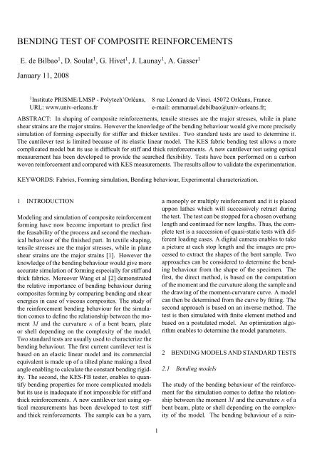
BENDING TEST OF COMPOSITE REINFORCEMENTS<br />
E. de Bilbao 1 , D. Soulat 1 , G. Hivet 1 , J. Launay 1 , A. Gasser 1<br />
January 11, 2008<br />
1 Institute PRISME/LMSP - Polytech’Orléans, 8 rue Léonard de Vinci. 45072 Orléans, France.<br />
URL: www.univ-orleans.fr<br />
e-mail: emmanuel.debilbao@univ-orleans.fr;<br />
ABSTRACT: In shaping <strong>of</strong> <strong>composite</strong> <strong>reinforcements</strong>, tensile stresses are the major stresses, while in plane<br />
shear strains are the major strains. However the knowledge <strong>of</strong> the <strong>bending</strong> behaviour would give more precisely<br />
simulation <strong>of</strong> forming especially for stiffer and thicker textiles. Two standard <strong>test</strong>s are used to determine it.<br />
The cantilever <strong>test</strong> is limited because <strong>of</strong> its elastic linear model. The KES fabric <strong>bending</strong> <strong>test</strong> allows a more<br />
complicated model but its use is difficult for stiff and thick <strong>reinforcements</strong>. A new cantilever <strong>test</strong> using optical<br />
measurement has been developed to provide the searched flexibility. Tests have been performed on a carbon<br />
woven reinforcement and compared with KES measurements. The results allow to validate the experimentation.<br />
KEYWORDS: Fabrics, Forming simulation, Bending behaviour, Experimental characterization.<br />
1 INTRODUCTION<br />
Modeling and simulation <strong>of</strong> <strong>composite</strong> reinforcement<br />
forming have now become important to predict first<br />
the feasability <strong>of</strong> the process and second the mechanical<br />
behaviour <strong>of</strong> the finished part. In textile shaping,<br />
tensile stresses are the major stresses, while in plane<br />
shear strains are the major strains [1]. However the<br />
knowledge <strong>of</strong> the <strong>bending</strong> behaviour would give more<br />
accurate simulation <strong>of</strong> forming especially for stiff and<br />
thick fabrics. Moreover Wang et al [2] demonstrated<br />
the relative importance <strong>of</strong> <strong>bending</strong> behaviour during<br />
<strong>composite</strong>s forming by comparing <strong>bending</strong> and shear<br />
energies in case <strong>of</strong> viscous <strong>composite</strong>s. The study <strong>of</strong><br />
the reinforcement <strong>bending</strong> behaviour for the simulation<br />
comes to define the relationship between the moment<br />
M and the curvature κ <strong>of</strong> a bent beam, plate<br />
or shell depending on the complexity <strong>of</strong> the model.<br />
Two standard <strong>test</strong>s are usually used to characterize the<br />
<strong>bending</strong> behaviour. The first current cantilever <strong>test</strong> is<br />
based on an elastic linear model and its commercial<br />
equivalent is made up <strong>of</strong> a tilted plane making a fixed<br />
angle enabling to calculate the constant <strong>bending</strong> rigidity.<br />
The second, the KES-FB <strong>test</strong>er, enables to quantify<br />
<strong>bending</strong> properties for more complicated models<br />
but its use is inadequate if not impossible for stiff and<br />
thick <strong>reinforcements</strong>. A new cantilever <strong>test</strong> using optical<br />
measurements has been developed to <strong>test</strong> stiff<br />
and thick <strong>reinforcements</strong>. The sample can be a yarn,<br />
a monoply or multiply reinforcement and it is placed<br />
uppon lathes which will successively retract during<br />
the <strong>test</strong>. The <strong>test</strong> can be stopped for a chosen overhang<br />
length and continued for new lengths. Thus, the complete<br />
<strong>test</strong> is a succession <strong>of</strong> quasi-static <strong>test</strong>s with different<br />
loading cases. A digital camera enables to take<br />
a picture at each stop length and the images are processed<br />
to extract the shapes <strong>of</strong> the bent sample. Two<br />
approaches can be considered to determine the <strong>bending</strong><br />
behaviour from the shape <strong>of</strong> the specimen. The<br />
first, the direct method, is based on the computation<br />
<strong>of</strong> the moment and the curvature along the sample and<br />
the drawing <strong>of</strong> the moment-curvature curve. A model<br />
can then be determined from the curve by fitting. The<br />
second approach is based on an inverse method. The<br />
<strong>test</strong> is then simulated with finite element method and<br />
based on a postulated model. An optimization algorithm<br />
enables to determine the model parameters.<br />
2 BENDING MODELS AND STANDARD TESTS<br />
2.1 Bending models<br />
The study <strong>of</strong> the <strong>bending</strong> behaviour <strong>of</strong> the reinforcement<br />
for the simulation comes to define the relationship<br />
between the moment M and the curvature κ <strong>of</strong> a<br />
bent beam, plate or shell depending on the complexity<br />
<strong>of</strong> the model. The <strong>bending</strong> behaviour <strong>of</strong> a rein-<br />
1
forcement is a multiscale hierarchical problem. At<br />
microscopic scale, the yarn is constitued with fibers<br />
which interact with the others and the <strong>bending</strong> rididity<br />
<strong>of</strong> the yarn is not the sum <strong>of</strong> the <strong>bending</strong> rigidity <strong>of</strong> the<br />
fibers. Relationship between fabric behaviour, structural<br />
configuration and mechanical behaviour <strong>of</strong> yarns<br />
and their constituent fibres is complex and a critical<br />
review has been wrote by Ghosh et al in [3]. At mesoscopic<br />
scale, the bibliography provides several analytical<br />
models for plain-woven fabrics taking into account<br />
the yarn section at crossover, the shape <strong>of</strong> the<br />
yarn, the contact condition at thread crossover, the set<br />
<strong>of</strong> yarn... More recently, Yu et al [4] considered that<br />
<strong>bending</strong> rigidity is dependent on the in-plane stiffness<br />
and proposed a non-orthogonal model based on asymmetric<br />
axial modulus defining bilinear behaviour over<br />
the range <strong>of</strong> tension to compression. At macroscopic<br />
scale, the most classical model is the linear elastic<br />
Peirce’s model used with his <strong>bending</strong> <strong>test</strong>. The other<br />
classical model is the Grosberg’s model used with the<br />
KES <strong>bending</strong> <strong>test</strong>. Past the non-linear region, the moment<br />
per unit length M is expressed by :<br />
M = M 0 + B f κ ifκ ≥ M 0 /B f (1)<br />
where M 0 is the frictional restraint force (moment<br />
per unit width) and B f is the flexural rigidity per unit<br />
width.<br />
2.2 Standard <strong>bending</strong> <strong>test</strong>s<br />
Peirce was the first to present a macroscopic measurement<br />
<strong>of</strong> the <strong>bending</strong> behaviour [5]. Assuming an elastic<br />
linear behaviour between the <strong>bending</strong> moment and<br />
the curvature <strong>of</strong> the strip, he proposed a cantilever <strong>test</strong><br />
(fig. 1) to determine the <strong>bending</strong> stiffness. In this <strong>test</strong><br />
the fabric is cantilevered under gravity.<br />
In this model, <strong>bending</strong> moment M is a linear function<br />
<strong>of</strong> the curvature κ:<br />
M = G × b × κ (2)<br />
where G is the flexural rigidity per unit width and b is<br />
the width <strong>of</strong> the strip. Peirce defined the ratio S <strong>of</strong> the<br />
flexural rigidity to the weigth w per unit length:<br />
S = G/w (3)<br />
Assuming the fabric being an elastic with small<br />
strains but large deflections, he defined the relation<br />
between the ratio S, the angle θ <strong>of</strong> the chord with the<br />
horizontal axis and the length L <strong>of</strong> the bent part <strong>of</strong> the<br />
sample (fig. 1)<br />
S = l3 8<br />
· cos θ/2<br />
tanθ<br />
Figure 1: Peirce’s <strong>test</strong><br />
(4)<br />
Computing the cubic root <strong>of</strong> S gives a like a length<br />
parameter, the <strong>bending</strong> length, which allows to compare<br />
the fabrics. The commercial apparatus is made<br />
up <strong>of</strong> a tilted plane making an angle θ = 41.5 ◦ . With<br />
this value, the formula becomes simpler :<br />
S ≈ l 3 /8 (5)<br />
This configuration is described in standard <strong>test</strong>s [6, 7].<br />
KES-FB <strong>test</strong>er is the <strong>test</strong> for quantifying <strong>bending</strong><br />
property in pure <strong>bending</strong> deformation mode and enables<br />
then to record directly the evolution <strong>of</strong> the <strong>bending</strong><br />
momentum per unit width with the curvature on a<br />
X-Y recorder unit during a load unload cycle. The<br />
<strong>bending</strong> rigidity and the <strong>bending</strong> hysteresis <strong>of</strong> Grosberb’s<br />
model are also computed.<br />
The dimension <strong>of</strong> the sample in the <strong>bending</strong> direction<br />
is equal to 1 cm and its length is 20 cm for<br />
flexible fabrics. It is clamped between a fixed and<br />
a moving clamps. The fixture setting <strong>of</strong> the sample<br />
in the clamps ensures pure <strong>bending</strong> deformation.<br />
During the <strong>test</strong>, the moving clamp rotates around<br />
the fixed ensuring a constant curvature through the<br />
sample length. The movement is made with a constant<br />
rate <strong>of</strong> curvature equal to 0.5 cm −1 s −1 from<br />
−2.5 cm −1 to 2.5 cm −1 . The apparatus was developed<br />
for flexible textiles and <strong>test</strong>ing stiff and thick<br />
<strong>reinforcements</strong> leads to reduce the length or can become<br />
impossible to perform.<br />
2
3 NEW FLEXOMETER<br />
3.1 General working<br />
The new flexometer comprises two modulus: a mechanical<br />
modulus and an optical modulus. The mechanical<br />
modulus enables to place the sample in cantilever<br />
configuration under its own weigth and possibly<br />
with additional mass. The optical modulus enables<br />
to capture the shape <strong>of</strong> the bent sample. The<br />
sample can be a yarn, a monoply or multiply reinforcement.<br />
It has a length about 300 mm and a width<br />
to 150 mm. The thickness can reach several millimeters.<br />
At the begining <strong>of</strong> the <strong>test</strong>, the sample is placed<br />
uppon a special plane (fig. 2) comprising lathes. A<br />
translucent plate is fixed uppon the both to ensure the<br />
embedding condition. Thus the sample will not slid.<br />
During the <strong>test</strong>, the lathes will successively retract<br />
and the length <strong>of</strong> overhang will increase. The <strong>test</strong> is<br />
stopped for a chosen overhang length and continued<br />
for new lengths. Thus, the complete <strong>test</strong> is a succession<br />
<strong>of</strong> quasi-static <strong>test</strong>s with different loading cases.<br />
While single cantilever <strong>test</strong> provides only one configuration,<br />
the new flexometer with its set <strong>of</strong> loading<br />
cases will enable to construct a non linear behaviour<br />
model because it provides different bent shapes with<br />
differents loading cases. A digital camera takes a picture<br />
at each stop length and the images are processed<br />
to extract the shapes <strong>of</strong> the bent sample. The following<br />
step is to extract the mean pr<strong>of</strong>il. Two approaches<br />
can be considered to determine the <strong>bending</strong> behaviour<br />
from the shape <strong>of</strong> the specimen. The first, the direct<br />
method, is based on the computation <strong>of</strong> the moment<br />
and the curvature along the sample and the drawing<br />
<strong>of</strong> the moment-curvature curve. A model can then be<br />
determined from the curve by fitting. The second approach<br />
is based on an inverse method. The <strong>test</strong> is then<br />
simulated with finite element method and based on a<br />
postulated model. An optimization algorithm enables<br />
to determine the model parameters.<br />
3.2 Direct method<br />
In this approach, the shape <strong>of</strong> the bent sample is defined<br />
by a set <strong>of</strong> XY data points and the <strong>bending</strong> moment<br />
and the curvature have to be computed along<br />
the sample. Because the shape is represented by a<br />
set <strong>of</strong> noisy data points it is not easy to compute directly<br />
the moment and the curvature and it is necessary<br />
to smooth the measured coordinates data using<br />
functions. A global polynom <strong>of</strong> exponential functions<br />
has been chosen to fit the set <strong>of</strong> points. A first order<br />
polynom is added to ensure the boundary conditions.<br />
n∑<br />
z(x) = p i e i∗K∗x + k 1 x + k 0 (6)<br />
i=1<br />
Figure 2: Flexometer<br />
With K an amplification factor to fit accuratly the<br />
points.<br />
The degree n <strong>of</strong> the exponential polynom is defined<br />
to optimize the parameters with the least square<br />
criterium.<br />
For a current point, P, (fig. 3) with (X P , Z P ) coordinates,<br />
its curvilinear coordinate is given by :<br />
s =<br />
∫ xP<br />
x 0<br />
√<br />
1 + z<br />
′2<br />
du (7)<br />
and the <strong>bending</strong> moment can be computed as :<br />
∫ L<br />
M(P) = w (u − s)cos(ϕ)du (8)<br />
s<br />
3
width. KES <strong>test</strong>s have been performed at ENSISA<br />
<strong>of</strong> Mulhouse. One can notice a good correlation between<br />
both <strong>test</strong>s. This comparison allows to validate<br />
the flexometer.<br />
Figure 3: Moment computing<br />
For each length <strong>of</strong> <strong>bending</strong> <strong>test</strong>, momentcurvature<br />
graph can be drawn. If the set <strong>of</strong> graphs are<br />
superposed, the behaviour is elastic and the momentcurvature<br />
graph for the greater length enables to define<br />
a <strong>bending</strong> model. If not, for each length <strong>of</strong><br />
<strong>bending</strong> <strong>test</strong>, the moment and the curvature computed<br />
at embedding point enable to draw a point on the<br />
moment-curvature load graph.<br />
3.3 Test and validation<br />
Tests have been performed on a 2.5D carbon woven<br />
reinforcement and compared with KES results (fig.<br />
4). The sample is 0.62 mm thick and its weigth is<br />
630 g/m 2 . For the flexometer it was 50 mm width<br />
and 300 mm long.<br />
M (N.mm /mm)<br />
0.09<br />
0.08<br />
0.07<br />
0.06<br />
0.05<br />
0.04<br />
0.03<br />
0.02<br />
0.01<br />
M=f(K)<br />
Flexo vs KES<br />
0.00<br />
0.00 0.01 0.02 0.03 0.04 0.05 0.06<br />
K (mm−1)<br />
Figure 4: Flexometer results vs KES<br />
For the KES-FB, it has been reduced to 30 mm<br />
Flexo<br />
KES<br />
4<br />
4 CONCLUSIONS<br />
The fabric <strong>bending</strong> behaviour is a complex multiscale<br />
mechanical problem and it is not possible to predict<br />
accuratly the <strong>bending</strong> behaviour from only the yarns<br />
properties with the present analytical models . At<br />
macroscopic scale <strong>bending</strong> behaviour is described by<br />
the constitutive moment curvature relationship which<br />
is not linear . Because standard <strong>bending</strong> <strong>test</strong>s for<br />
fabrics are not adequate, a new cantilever <strong>test</strong> has<br />
been disigned. Tests performed on a carbon woven<br />
reinforcement have allowed to validate this new <strong>test</strong><br />
and the direct method. Therefore, the direct method<br />
doesn’t able to define unload behaviour because <strong>of</strong> the<br />
difficulty to compute with good accurate the low curvatures.<br />
Thereby the second approach based on an<br />
inverse method will be investigated in the next step.<br />
ACKNOWLEDGEMENT<br />
All our thanks to Laurence Schacher <strong>of</strong> the Laboratoire de<br />
Physique et Mécanique Textiles de Mulhouse ( ENSISA) to have<br />
allowed us to perform the KES <strong>bending</strong> <strong>test</strong>s.<br />
REFERENCES<br />
[1] P Boisse, B Zouari, and JL Daniel. Importance <strong>of</strong> in-plane<br />
shear rigidity in finite element analyses <strong>of</strong> woven fabric<br />
<strong>composite</strong> preforming. Composites Part A: Applied Science<br />
and Manufacturing, 37:2201–2212, December 2006.<br />
[2] Jinhuo Wang, Andrew C. Long, Michael J. Clifford, and<br />
Hua Lin. Energy analysis <strong>of</strong> reinforcement deformations<br />
during viscous textile <strong>composite</strong> forming. In Elias Cueto<br />
and Francisco Chinesta, editors, AIP Conference Proceedings,<br />
volume 907, pages 1098–1106. AIP, 2007.<br />
[3] TK Ghosh, SK Batr, and RL Barke. The <strong>bending</strong> behaviour<br />
<strong>of</strong> plain-woven fabrics. part i : A critical review. The Journal<br />
<strong>of</strong> the Textile Institute, 81:245–254, 1990.<br />
[4] WR Yu, M Zampaloni, F Pourboghrat, K Chung, and<br />
TJ Kang. Analysis og flexible <strong>bending</strong> bahavior <strong>of</strong> woven<br />
preform using non-orthogonal constitutive equation. Composite<br />
Part A : Applied science and manufacturing, 36<br />
(6):839–850, 2005.<br />
[5] FT Peirce. The ’handle’ <strong>of</strong> cloth as a measurable quantity.<br />
The Journal <strong>of</strong> the Textile Institute, 21:377–416, 1930.<br />
[6] ASTM. Standard Test Method for Stiffness <strong>of</strong> fabrics, chapter<br />
D1388-96(2002). American Society for Testing and Materials,<br />
2002.<br />
[7] ISO. Textiles glass -Woven fabrics - Determination <strong>of</strong> conventional<br />
flexural stifness - Fixed angle flexometer method,<br />
chapter iSO 4604:1978. ISO, 1978.