Laser-assisted machining of Inconel 718 with carbide and ceramic ...
Laser-assisted machining of Inconel 718 with carbide and ceramic ...
Laser-assisted machining of Inconel 718 with carbide and ceramic ...

You also want an ePaper? Increase the reach of your titles
YUMPU automatically turns print PDFs into web optimized ePapers that Google loves.
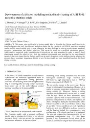
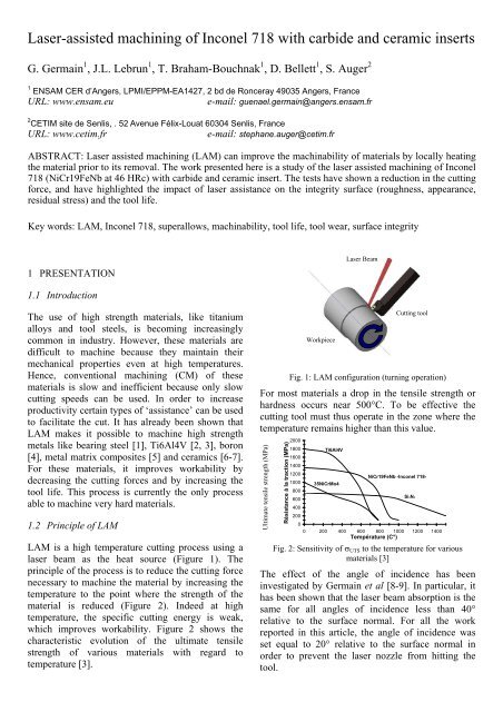
<strong>Laser</strong>-<strong>assisted</strong> <strong>machining</strong> <strong>of</strong> <strong>Inconel</strong> <strong>718</strong> <strong>with</strong> <strong>carbide</strong> <strong>and</strong> <strong>ceramic</strong> insertsG. Germain 1 , J.L. Lebrun 1 , T. Braham-Bouchnak 1 , D. Bellett 1 , S. Auger 21 ENSAM CER d’Angers, LPMI/EPPM-EA1427, 2 bd de Ronceray 49035 Angers, FranceURL: www.ensam.eue-mail: guenael.germain@angers.ensam.fr2 CETIM site de Senlis, . 52 Avenue Félix-Louat 60304 Senlis, FranceURL: www.cetim.fre-mail: stephane.auger@cetim.frABSTRACT: <strong>Laser</strong> <strong>assisted</strong> <strong>machining</strong> (LAM) can improve the machinability <strong>of</strong> materials by locally heatingthe material prior to its removal. The work presented here is a study <strong>of</strong> the laser <strong>assisted</strong> <strong>machining</strong> <strong>of</strong> <strong>Inconel</strong><strong>718</strong> (NiCr19FeNb at 46 HRc) <strong>with</strong> <strong>carbide</strong> <strong>and</strong> <strong>ceramic</strong> insert. The tests have shown a reduction in the cuttingforce, <strong>and</strong> have highlighted the impact <strong>of</strong> laser assistance on the integrity surface (roughness, appearance,residual stress) <strong>and</strong> the tool life.Key words: LAM, <strong>Inconel</strong> <strong>718</strong>, superallows, machinability, tool life, tool wear, surface integrity1 PRESENTATION<strong>Laser</strong> BeamFaisceau <strong>Laser</strong>1.1 IntroductionThe use <strong>of</strong> high strength materials, like titaniumalloys <strong>and</strong> tool steels, is becoming increasinglycommon in industry. However, these materials aredifficult to machine because they maintain theirmechanical properties even at high temperatures.Hence, conventional <strong>machining</strong> (CM) <strong>of</strong> thesematerials is slow <strong>and</strong> inefficient because only slowcutting speeds can be used. In order to increaseproductivity certain types <strong>of</strong> ‘assistance’ can be usedto facilitate the cut. It has already been shown thatLAM makes it possible to machine high strengthmetals like bearing steel [1], Ti6Al4V [2, 3], boron[4], metal matrix composites [5] <strong>and</strong> <strong>ceramic</strong>s [6-7].For these materials, it improves workability bydecreasing the cutting forces <strong>and</strong> by increasing thetool life. This process is currently the only processable to machine very hard materials.1.2 Principle <strong>of</strong> LAMLAM is a high temperature cutting process using alaser beam as the heat source (Figure 1). Theprinciple <strong>of</strong> the process is to reduce the cutting forcenecessary to machine the material by increasing thetemperature to the point where the strength <strong>of</strong> thematerial is reduced (Figure 2). Indeed at hightemperature, the specific cutting energy is weak,which improves workability. Figure 2 shows thecharacteristic evolution <strong>of</strong> the ultimate tensilestrength <strong>of</strong> various materials <strong>with</strong> regard totemperature [3].PièceWorkpieceOutil de coupeCutting toolFig. 1: LAM configuration (turning operation)For most materials a drop in the tensile strength orhardness occurs near 500°C. To be effective thecutting tool must thus operate in the zone where thetemperature remains higher than this value.Ultimate tensile strength (MPa)Résistance à la traction (MPa)2000180016001400120010008006004002000Ti6Al4V35NiCrMo4NiCr19FeNb -<strong>Inconel</strong> <strong>718</strong>-Si3N40 200 400 600 800 1000 1200 1400Température (C°)Fig. 2: Sensitivity <strong>of</strong> σ UTS to the temperature for variousmaterials [3]The effect <strong>of</strong> the angle <strong>of</strong> incidence has beeninvestigated by Germain et al [8-9]. In particular, ithas been shown that the laser beam absorption is thesame for all angles <strong>of</strong> incidence less than 40°relative to the surface normal. For all the workreported in this article, the angle <strong>of</strong> incidence wasset equal to 20° relative to the surface normal inorder to prevent the laser nozzle from hitting thetool.
1.3 Experimental equipmentA numerically controlled lathe (REALMECA RT-5)equipped <strong>with</strong> a 2.5 kW ROFIN YAG laser was usedin this work. The laser nozzle can be controlled usingthree translations <strong>and</strong> two rotations. A numericalcontrol system (NUM 1060) allows the control <strong>of</strong> theseven independent degrees <strong>of</strong> freedom. The highpowerlaser beam is delivered through a fibre opticcable to the lathe chamber, where it is focused on theworkpiece surface. During <strong>machining</strong>, a gas underpressure (air) is forced through the laser nozzle toprotect the focusing lens from being damaged bychips. Three components <strong>of</strong> the cutting force aremeasured by a Kistler piezoelectric dynamometer.1.4 Material investigatedThe material under investigation is the nickel alloyNiCr19FeNb which is known commercially as<strong>Inconel</strong> <strong>718</strong>. It has been structurally hardened via aheat treatment consisting <strong>of</strong> quenching (from 940 to1010 ° C) <strong>and</strong> structural hardening (720 ° C for 8 hrfollowed by 620 ° C for 8 h). The microstructure isaustenitic <strong>with</strong> a grain size index <strong>of</strong> G=10. Thehardness <strong>of</strong> the material is uniform <strong>and</strong> has anaverage value <strong>of</strong> 482 HV (46 HRc).1.5 Cutting parameters used <strong>with</strong> the <strong>carbide</strong> insertTests were carried out <strong>with</strong> the cutting parametersrecommended by the CETIM for this type <strong>of</strong> insert<strong>and</strong> <strong>with</strong> several laser Powers: 0 Watts (conventional<strong>machining</strong>), 1165 <strong>and</strong> 1975 Watts. The cuttingparameters recommended are: Carbide tool insertKC5525 (Kennametal) ref. CNMG 120412 RP;advance, f = 0.2 mm/rev; cutting depth, ap = 2.5mm; cutting speed, Vc = 30 m/min; <strong>with</strong>outlubrication. Material removal rate <strong>of</strong> 15 cm 3 .min -1 . Anew cutting edge was used for each test. The laserbeam was focused on the chamfered cut surfaceapproximately 5 mm from the cutting tool.The three components <strong>of</strong> the cutting force, thesurface integrity (roughness, residual stresses), <strong>and</strong>the tool life were measured for each test.1.6 Parameters used <strong>with</strong> the <strong>ceramic</strong> insertSimilarly, the cutting parameters used for the<strong>ceramic</strong> insert are those recommended by theCETIM: CC670 <strong>ceramic</strong> insert (S<strong>and</strong>vik) ref. RNGN090300; advance, f = 0.18 mm/rev; cutting depth, ap= 1.5 mm; cutting speed, Vc = 220 m/min; <strong>with</strong>outlubrication. Material removal rate <strong>of</strong> 59.4 cm 3 .min -1 .The tests were carried out <strong>with</strong>out laser assistance<strong>and</strong> <strong>with</strong> an assistance <strong>of</strong> 1500 Watts. The evolution<strong>of</strong> the tool wear, the three components <strong>of</strong> the cuttingforce, <strong>and</strong> the surface roughness, were measured foreach test. The tool life <strong>and</strong> residual surface stresseswere also determined.2 RESULTS OBTAINED WITH THE CARBIDEINSERT2.1 Cutting force (<strong>carbide</strong> insert)The results show a decrease magnitude <strong>of</strong> the cuttingforce <strong>with</strong> the laser power (Figure.3). Specifically,there is a decrease <strong>of</strong> 6.5% <strong>with</strong> a laser power <strong>of</strong>1165 W <strong>and</strong> 10.8% <strong>with</strong> a power <strong>of</strong> 1975 W.Force intensity (N)180017001600150014001300120011001000900800700600500400Axiale forceTangentiale forceRadiale forceCutting force (norme)0 500 1000 1500 2000<strong>Laser</strong> power (W)Fig 3: Evolution <strong>of</strong> the three components <strong>and</strong> the magnitude <strong>of</strong>the cutting force as a function <strong>of</strong> the laser power2.2 Surface Integrity (<strong>carbide</strong> insert)The impact <strong>of</strong> laser assistance on the surfaceintegrity has been quantified by the evolution <strong>of</strong>several roughness criteria <strong>and</strong> the residual stresseson the cut surface. The three surface roughnesscriteria used are: the arithmetic average (Ra), themaximum height peak/valley (Rmax) <strong>and</strong> theaverage height peak/valley (Rz). The followingfigure (Figure 4) shows that laser assistance caninfluence the surface roughness <strong>of</strong> the workpiece. Ahigh laser power results in a slight improvement <strong>of</strong>the roughness criteria.Roughness (µm)6543210Withoutassistance1165 W 1975 W<strong>Laser</strong> power (W)RaRmaxRzFig 4: Evolution <strong>of</strong> the surface roughness as a function <strong>of</strong> laserpowerThe residual stresses were determined by X-raydiffraction. The analysis was carried out for the test<strong>with</strong>out assistance (conventional <strong>machining</strong> - CM),
<strong>and</strong> <strong>with</strong> the maximum laser power. The valuesobtained are summarised in the following table(Table1).Table 1. Residual Stresses values on the cut surfaceStress (MPa)CMLAM1975 WAxial direction 740 ± 25 520 ± 30Tangential direction 435 ± 45 440 ± 45The table shows that the residual stresses on thesurface are positive (tensile stresses) for the twotests. The laser assistance decreases the residualstress in the axial direction.2.3 Tool wear (<strong>carbide</strong> insert)These initial results demonstrate an improvement inthe machinability <strong>of</strong> <strong>Inconel</strong> <strong>718</strong> <strong>with</strong> laserassistance. However, the improvement is modest <strong>and</strong>there is a significant drop in tool life <strong>with</strong> the use <strong>of</strong>laser assistance. Indeed, the tool life is only 50sec<strong>with</strong> the laser assistance, compared to approximately2min 50sec in conventional <strong>machining</strong>. In bothcases, the insert deteriorates very quickly <strong>with</strong> analmost instant failure <strong>of</strong> the cutting edge.3 RESULTS OBTAINED WITH THE CERAMICINSERT3.1 Cutting force (<strong>ceramic</strong> insert)The figure below (Figure 5) shows the evolution <strong>of</strong>the magnitude <strong>of</strong> the cutting force as a function <strong>of</strong>the distance machined for both conventional<strong>machining</strong> <strong>and</strong> LAM (1500 Watts). The cuttingforce in LAM is lower than in CM. Depending ontool wear, the reduction in the cutting force in UALis between 40% <strong>and</strong> 20%.Cutting force (N)240019001400900400LAM (1500 W)Without <strong>Laser</strong> (CM)0 200 400 600 800 1000 1200 1400 1600 1800Length machined (m)Fig 5: Evolution <strong>of</strong> the magnitude <strong>of</strong> the cutting force, in CM<strong>and</strong> in LAM, as a function <strong>of</strong> the distance machinedInserts have machined respectively 1500m in LAM<strong>and</strong> 1650m in conventional <strong>machining</strong> prior to thecollapse <strong>of</strong> the cutting edge. The beginning <strong>of</strong> thedeteriorated area appears more rapidly in LAM(1200 m) than CM (1400 m). This deteriorationresults in an increase <strong>of</strong> the radial <strong>and</strong> axialcomponents <strong>of</strong> the cutting force, but not thetangential component.3.2 Surface Integrity (<strong>ceramic</strong> insert)The surface integrity was quantified by themeasurement <strong>of</strong> surface roughness (three criteria:Ra, Rmax <strong>and</strong> Rz), by the determination <strong>of</strong> surfaceresidual stresses <strong>and</strong> by examination <strong>of</strong> the cutsurface <strong>with</strong> a scanning electron microscope (SEM).The three roughness criteria show the same trend.Consequently only the Ra criterion is presented infigure 6.Roughness, Ra (µm)3,53,02,52,01,51,00,5LAM (1500W)Without <strong>Laser</strong> (CM)0,00 200 400 600 800 1000 1200 1400 1600 1800Length machined (m)Fig 6: Evolution <strong>of</strong> the surface roughness (Ra), in CM <strong>and</strong>LAM, as a function <strong>of</strong> the distance machinedIt can be seen that the evolutions <strong>of</strong> Ra, in CM <strong>and</strong>LAM, are similar up to a machined distance <strong>of</strong>approximately 800 m. After this distance, theroughness is lower <strong>and</strong> less dispersed for LAM. Forconventional <strong>machining</strong> after approximately 800 m,the roughness increase significantly <strong>and</strong> the data iswidely scattered (scratches due to chips).The analysis <strong>of</strong> residual stress was performed usinga PROTO X-ray diffraction machine. The followingtable (Table 2) summarises the values <strong>of</strong> residualstress at the surface for the two types <strong>of</strong> <strong>machining</strong>.Table 2: Surface residual stressesStress (MPa)CMLAM1500 WAxial direction 160 ± 35 260 ± 35Tangential direction 270 ± 30 555 ± 45These values indicate that these cutting parametersresult in positive or tensile residual stresses in bothdirections. In addition, LAM generates higherstresses due to thermal effects <strong>of</strong> laser heating.These values confirm the results obtained in othermaterials [9] <strong>and</strong> those found during the tests <strong>with</strong><strong>carbide</strong> inserts.The machined surfaces were observed <strong>with</strong> ascanning electron microscope. The figure 7 belowshows pictures <strong>of</strong> the machined surfaces in CM (a)
<strong>and</strong> LAM (b).For a maximum wear criterion set at Vb = 0.3 mm(ISO st<strong>and</strong>ard), the tool life is 4min 25sec in CM<strong>and</strong> 5min 40sec in LAM.4 CONCLUSIONS(a)(b)Fig 7: SEM photos <strong>of</strong> the machined surfaces in (a) CM <strong>and</strong> (b)LAM.These photos (taken at the same magnification)demonstrate that the surface quality is considerablyhigher in LAM than in CM. In CM, the surfaceappears to be torn <strong>and</strong> dark spots, evenly distributedover the machined area, can be observed.Electron Diffusion Spectrometer (EDS) analyseswere conducted to determine the nature <strong>of</strong> these darkspots. The EDS analyses show that all <strong>of</strong> the darkspots are caused by pollution <strong>of</strong> the surface by thetool insert. The presence <strong>of</strong> these elements (silicon,nitrogen, oxygen <strong>and</strong> aluminium) corresponds to amaterial deposit from the tool insert. Thisphenomenon is only visible on the conventionalmachined specimens. The machined parts in LAMdemonstrate no such pollution.3.3 Tool wear (<strong>ceramic</strong> insert)The evolution <strong>of</strong> the wear on the clearance face, Vb,is shown in figure 8, for the two types <strong>of</strong> <strong>machining</strong>,as a function <strong>of</strong> the machined distance. Theevolution <strong>of</strong> the clearance wear is different for<strong>machining</strong> <strong>with</strong> <strong>and</strong> <strong>with</strong>out laser assistance. Inconventional <strong>machining</strong> clearance wear increasesapproximately linearly, while for LAM three areas<strong>of</strong> change are visible.Wear, Vb (mm)0,60,50,40,30,20,1LAM (1500W)Without <strong>Laser</strong> (CM)Vb = 0.3 mm00 500 1000 1500 2000Lenght machined (m)Fig 8: Evolution <strong>of</strong> wear (Vb) as a function <strong>of</strong> the machineddistanceIn LAM, at the beginning <strong>of</strong> <strong>machining</strong>, up to about400 m, the wear increases rapidly (run-in). Thenbetween about 400 <strong>and</strong> 1000 m, the wear isrelatively stable in LAM. By contrast, from 1000 mthe degradation <strong>of</strong> the tool is greater in LAM <strong>with</strong> avery rapid increase in clearance wear.This study, on the laser <strong>assisted</strong> <strong>machining</strong> <strong>of</strong><strong>Inconel</strong> <strong>718</strong> has highlighted significant differencesbetween the use <strong>of</strong> <strong>carbide</strong> inserts <strong>and</strong> <strong>ceramic</strong>inserts. In addition, comparisons <strong>with</strong> conventional<strong>machining</strong> were also conducted. Tests have shownthat, no matter which insert is used, LAMsignificantly reduces the cutting force (up to 40%).The integrity <strong>of</strong> the machined surface, in terms <strong>of</strong>roughness, is not improved <strong>with</strong> the use <strong>of</strong> <strong>ceramic</strong>inserts in LAM compared to CM. However, thisgain is not visible <strong>with</strong> <strong>carbide</strong> inserts. Ceramicinserts allow a very good performance during thelaser <strong>assisted</strong> <strong>machining</strong>, unlike <strong>carbide</strong> inserts. Infact, the life <strong>of</strong> a <strong>carbide</strong> insert in LAM isconsiderably lower than its life in CM, whereas thelife <strong>of</strong> <strong>ceramic</strong> inserts in LAM increase by 25%compared to the life in CM.REFERENCES[1] Kainth G.S., Dey B.K., Experimental investigation into toollife <strong>and</strong> temperature during hot <strong>machining</strong> <strong>of</strong> EN-24 steels,Bulletin Cercle Etudes des Métaux 14 n°11 (1980) p22.1-22.7[2] Kitagawa T., Katsuhiro K., Kudo A., Plasma hot <strong>machining</strong>for high hardness metals, Bulletin Japon Society <strong>of</strong> PrecisionEngineering Vol.22 n°2 (1988) p145-151[3] Lesourd B., Etude et modélisation des mécanismes deformation de b<strong>and</strong>es de cisaillement intense en coupe desmétaux. Application au tournage assisté laser de l’alliage detitane TA6V, Thèse Ecole Centrale de Nantes (1996)[4] Malot T., Usinage assisté par laser du bore, ThèseUniversité de Bourgogne (2001)[5] Wang Y., Yang L.J., Wang N.J., An investigation <strong>of</strong> laser<strong>assisted</strong><strong>machining</strong> <strong>of</strong> Al 2 O 3 particule reinforced aluminiummatrix composite, Materials Processing Technologies 129(2002) p268-272[6] Rebro P.A., Shin Y.C., Incropera F.P, Design <strong>of</strong> operatingconditions for crackfree laser-<strong>assisted</strong> <strong>machining</strong> <strong>of</strong> mullite<strong>ceramic</strong>, International Journal <strong>of</strong> Machine Tools &Manufacture 44 (2004) p667-694.[7] Melhaoui A., Contribution à l’étude de l’usure d’outil decoupe en usinage asssité par laser et à l’usinabilité d’unecéramique à base d’oxyde de zinc, Thèse de l’ECP (1997)[8] Germain G., Lebrun J-L., Robert P., Dal Santo P., PoitouA., Experimental <strong>and</strong> numerical approaches <strong>of</strong> <strong>Laser</strong> <strong>assisted</strong>turning, IJFP Vol. 8 - Special Issue 2005, MultiscaleSimulations <strong>and</strong> Experiments to optimize Material FormingProcesses (2005) p347-361[9] Germain G., Morel F., Lebrun J-L., Morel A., Huneau B.,Effect <strong>of</strong> laser assistance <strong>machining</strong> on residual stress <strong>and</strong>fatigue strength for a bearing steel (100Cr6) <strong>and</strong> a titaniumalloy (Ti 6Al 4V), Materials Science Forum 524-525, (2006)p559-574