Laser-assisted machining of Inconel 718 with carbide and ceramic ...
Laser-assisted machining of Inconel 718 with carbide and ceramic ...
Laser-assisted machining of Inconel 718 with carbide and ceramic ...

You also want an ePaper? Increase the reach of your titles
YUMPU automatically turns print PDFs into web optimized ePapers that Google loves.
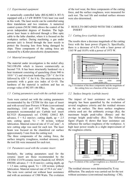
1.3 Experimental equipmentA numerically controlled lathe (REALMECA RT-5)equipped <strong>with</strong> a 2.5 kW ROFIN YAG laser was usedin this work. The laser nozzle can be controlled usingthree translations <strong>and</strong> two rotations. A numericalcontrol system (NUM 1060) allows the control <strong>of</strong> theseven independent degrees <strong>of</strong> freedom. The highpowerlaser beam is delivered through a fibre opticcable to the lathe chamber, where it is focused on theworkpiece surface. During <strong>machining</strong>, a gas underpressure (air) is forced through the laser nozzle toprotect the focusing lens from being damaged bychips. Three components <strong>of</strong> the cutting force aremeasured by a Kistler piezoelectric dynamometer.1.4 Material investigatedThe material under investigation is the nickel alloyNiCr19FeNb which is known commercially as<strong>Inconel</strong> <strong>718</strong>. It has been structurally hardened via aheat treatment consisting <strong>of</strong> quenching (from 940 to1010 ° C) <strong>and</strong> structural hardening (720 ° C for 8 hrfollowed by 620 ° C for 8 h). The microstructure isaustenitic <strong>with</strong> a grain size index <strong>of</strong> G=10. Thehardness <strong>of</strong> the material is uniform <strong>and</strong> has anaverage value <strong>of</strong> 482 HV (46 HRc).1.5 Cutting parameters used <strong>with</strong> the <strong>carbide</strong> insertTests were carried out <strong>with</strong> the cutting parametersrecommended by the CETIM for this type <strong>of</strong> insert<strong>and</strong> <strong>with</strong> several laser Powers: 0 Watts (conventional<strong>machining</strong>), 1165 <strong>and</strong> 1975 Watts. The cuttingparameters recommended are: Carbide tool insertKC5525 (Kennametal) ref. CNMG 120412 RP;advance, f = 0.2 mm/rev; cutting depth, ap = 2.5mm; cutting speed, Vc = 30 m/min; <strong>with</strong>outlubrication. Material removal rate <strong>of</strong> 15 cm 3 .min -1 . Anew cutting edge was used for each test. The laserbeam was focused on the chamfered cut surfaceapproximately 5 mm from the cutting tool.The three components <strong>of</strong> the cutting force, thesurface integrity (roughness, residual stresses), <strong>and</strong>the tool life were measured for each test.1.6 Parameters used <strong>with</strong> the <strong>ceramic</strong> insertSimilarly, the cutting parameters used for the<strong>ceramic</strong> insert are those recommended by theCETIM: CC670 <strong>ceramic</strong> insert (S<strong>and</strong>vik) ref. RNGN090300; advance, f = 0.18 mm/rev; cutting depth, ap= 1.5 mm; cutting speed, Vc = 220 m/min; <strong>with</strong>outlubrication. Material removal rate <strong>of</strong> 59.4 cm 3 .min -1 .The tests were carried out <strong>with</strong>out laser assistance<strong>and</strong> <strong>with</strong> an assistance <strong>of</strong> 1500 Watts. The evolution<strong>of</strong> the tool wear, the three components <strong>of</strong> the cuttingforce, <strong>and</strong> the surface roughness, were measured foreach test. The tool life <strong>and</strong> residual surface stresseswere also determined.2 RESULTS OBTAINED WITH THE CARBIDEINSERT2.1 Cutting force (<strong>carbide</strong> insert)The results show a decrease magnitude <strong>of</strong> the cuttingforce <strong>with</strong> the laser power (Figure.3). Specifically,there is a decrease <strong>of</strong> 6.5% <strong>with</strong> a laser power <strong>of</strong>1165 W <strong>and</strong> 10.8% <strong>with</strong> a power <strong>of</strong> 1975 W.Force intensity (N)180017001600150014001300120011001000900800700600500400Axiale forceTangentiale forceRadiale forceCutting force (norme)0 500 1000 1500 2000<strong>Laser</strong> power (W)Fig 3: Evolution <strong>of</strong> the three components <strong>and</strong> the magnitude <strong>of</strong>the cutting force as a function <strong>of</strong> the laser power2.2 Surface Integrity (<strong>carbide</strong> insert)The impact <strong>of</strong> laser assistance on the surfaceintegrity has been quantified by the evolution <strong>of</strong>several roughness criteria <strong>and</strong> the residual stresseson the cut surface. The three surface roughnesscriteria used are: the arithmetic average (Ra), themaximum height peak/valley (Rmax) <strong>and</strong> theaverage height peak/valley (Rz). The followingfigure (Figure 4) shows that laser assistance caninfluence the surface roughness <strong>of</strong> the workpiece. Ahigh laser power results in a slight improvement <strong>of</strong>the roughness criteria.Roughness (µm)6543210Withoutassistance1165 W 1975 W<strong>Laser</strong> power (W)RaRmaxRzFig 4: Evolution <strong>of</strong> the surface roughness as a function <strong>of</strong> laserpowerThe residual stresses were determined by X-raydiffraction. The analysis was carried out for the test<strong>with</strong>out assistance (conventional <strong>machining</strong> - CM),