A190123 - Imtex Controls
A190123 - Imtex Controls
A190123 - Imtex Controls

You also want an ePaper? Increase the reach of your titles
YUMPU automatically turns print PDFs into web optimized ePapers that Google loves.
Introduction<br />
Type AQ & IQ Valve Position Monitors are designed to provide high<br />
accuracy feedback of valve position to plant control systems.<br />
These instructions outline the requirements for ensuring a long and<br />
trouble free service life from the monitors.<br />
MONITOR - TRANSMITTER - AQ/IQ70<br />
12<br />
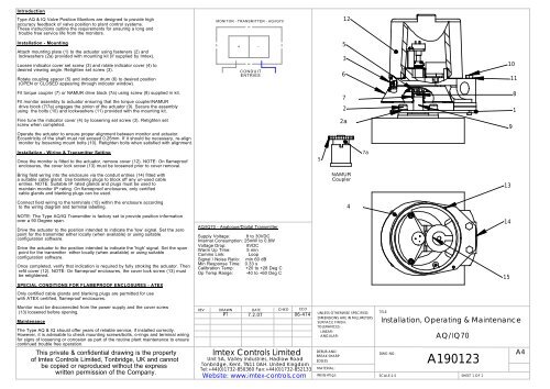
Installation - Mounting<br />
Attach mounting plate (1) to the actuator using fasteners (2) and<br />
lockwashers (2a) provided with mounting kit (if supplied by <strong>Imtex</strong>).<br />
Loosen indicator cover set screw (3) and rotate indicator cover (4) to<br />
desired viewing angle. Retighten set screw (3).<br />
Rotate coupling spacer (5) and indicator drum (6) to desired position<br />
(OPEN or CLOSED appearing through indicator window).<br />
+ -<br />
CONDUIT<br />
ENTRIES<br />
5<br />
3<br />
6<br />
10<br />
11<br />
Fit torque coupler (7) or NAMUR drive block (7a) using screw (8) supplied in kit.<br />
Fit monitor assembly to actuator ensuring that the torque coupler/NAMUR<br />
drive block (7/7a) engages the pinion of the actuator (9). Secure the assembly<br />
using the bolts (10) and lockwashers (11) provided with the mounting kit.<br />
7<br />
2<br />
8<br />
1<br />
Fine tune the indicator cover (4) by loosening set screw (3). Retighten set<br />
screw when completed.<br />
Operate the actuator to ensure proper alignment between monitor and actuator.<br />
Eccentricity of the shaft must not exceed 0.25mm. If it should be necessary, re-align<br />
monitor by loosening mount bolts (10). Retighten bolts when satisfied with alignment.<br />
2a<br />
9<br />
Installation - Wiring & Transmitter Setting<br />
Once the monitor is fitted to the actuator, remove cover (12). NOTE: On flameproof<br />
enclosures, the cover lock screw (13) must be loosened prior to cover removal.<br />
5<br />
7a<br />
Bring field wiring into the enclosure via the conduit entries (14) fitted with<br />
a suitable cable gland. Use blanking plugs to block off any un-used cable<br />
entries. NOTE: Suitable IP rated glands and plugs must be used to<br />
maintain monitor IP rating. On flameproof enclosures, only certified<br />
cable glands and blanking plugs can be used.<br />
NAMUR<br />
Coupler<br />
13<br />
Connect field wiring to the terminals (15) within the enclosure according<br />
to the wiring diagram and terminal labelling.<br />
4<br />
NOTE: The Type AQ/IQ Transmitter is factory set to provide position information<br />
over a 90 Degree span.<br />
Drive the actuator to the position intended to indicate the 'low' signal. Set the zero<br />
point for the transmitter either locally (when available) or using suitable<br />
configuration software.<br />
Drive the actuator to the position intended to indicate the 'high' signal. Set the span<br />
point for the transmitter either locally (when available) or using suitable<br />
configuration software.<br />
Once completed, verify that indication is required by fully stroking the actuator. Then<br />
refit cover (12). NOTE: On flameproof enclosures, the cover lock screw (13) must<br />
be retightened.<br />
AQ/IQ70 - Analogue/Digital Transmitter<br />
Supply Voltage: 8 to 30VDC<br />
Internal Consumption: 25mW to 0.8W<br />
Voltage Drop: 8VDC<br />
Warm Up Time: 5 min<br />
Comms Link: Loop<br />
Signal / Noise Ratio: min 60 dB<br />
Min Response Time: 0.33 s<br />
Calibration Temp: +20 to +28 Deg C<br />
Op Temp Range: -40 to +60 Deg C<br />
14<br />
15<br />
SPECIAL CONDITIONS FOR FLAMEPROOF ENCLOSURES - ATEX<br />
Only certified cable glands and blanking plugs are permitted for use<br />
with ATEX certified, flameproof enclosures.<br />
Monitor must be disconnected from the power supply and the cover screw<br />
(13) loosened before opening.<br />
Maintenance<br />
The Type AQ & IQ should offer years of reliable service, if installed correctly.<br />
However, it is advisable to check mounting screws/bolts, o-rings and terminal wiring<br />
for signs of loosening or corrosion as part of the routine plant maintenance to ensure<br />
continued trouble free operation.<br />
This private & confidential drawing is the property<br />
of <strong>Imtex</strong> <strong>Controls</strong> Limited, Tonbridge, UK and cannot<br />
be copied or reproduced without the express<br />
written permission of the Company.<br />
REV<br />
DRAWN<br />
PT<br />
DATE<br />
7.2.07<br />
CHK'D<br />
<strong>Imtex</strong> <strong>Controls</strong> Limited<br />
ECO<br />
06-474<br />
Unit 5A, Valley Industries, Hadlow Road<br />
Tonbridge, Kent, TN11 0AH. United Kingdom<br />
Tel:+44(0)1732-850360 Fax:+44(0)1732-852133<br />
Website: www.imtex-controls.com<br />
UNLESS OTHERWISE SPECIFIED:<br />
DIMENSIONS ARE IN MILLIMETERS<br />
SURFACE FINISH:<br />
TOLERANCES:<br />
LINEAR:<br />
ANGULAR:<br />
DEBUR AND<br />
BREAK SHARP<br />
EDGES<br />
MATERIAL:<br />
WEIGHT(g):<br />
TITLE:<br />
Installation, Operating & Maintenance<br />
AQ/IQ70<br />
DWG NO.<br />
<strong>A190123</strong><br />
SCALE:1:5<br />
SHEET 1 OF 1<br />
A4
Programming:<br />
PRetop 5335 can be configured in the following 3 ways:<br />
1 With communications interface Loop Link 5905 or 5909 and<br />
PReset PC configuration software.<br />
2. With a HART ® modem and PReset PC configuration software.<br />
3. With a HART ® communicator with PR DDL driver.<br />
1: Loop Link 5905A:<br />
For programming please refer to the drawing below and the help functions in<br />
PReset.<br />
Loop Link 5905A is not approved for communication with modules installed in<br />
hazardous (Ex) areas.<br />
App.i
Serial no:<br />
Tag no:<br />
8-10<br />
Pt100 DI<br />
3-wire<br />
--<br />
1.00 sec<br />
--<br />
--<br />
N/<br />
IEC<br />
Upscale<br />
Serial no:<br />
Tag no:<br />
8-10<br />
Pt100 DI<br />
0.00 - 50.<br />
3-wire<br />
--<br />
1.00 sec<br />
---<br />
-<br />
N/<br />
00 C<br />
IEC<br />
Upscale<br />
2: 5909 Loop Link - Connection of PR modules using EZ-Mini-Hooks:<br />
PR 5331, 5333, 5334, 5335<br />
1<br />
2<br />
11<br />
13<br />
(21)<br />
(23)<br />
Black<br />
Disconnect<br />
Red Yellow<br />
*<br />
*<br />
Green<br />
Receiving<br />
Equipment<br />
+Vsupply<br />
Input<br />
Connector<br />
* Connected only for<br />
on-line programming<br />
File Product Input Output Communicat<br />
PRetop 5331<br />
Date: 2004-<br />
ion Language Option 08:30:00<br />
043201594<br />
PRelectronics<br />
Analog input Analog output<br />
Input type: Output type: 4 - 20mA<br />
Sensor error:<br />
PR 6331, 6333, 6334, 6335<br />
Loop<br />
Link<br />
0.00 - 50.00 C<br />
Input range:<br />
Connection:<br />
Cold junction comp:<br />
Response time:<br />
USB cable<br />
Connection of PR modules using a modular connector:<br />
Programming cable<br />
with modular connector<br />
PR 5114, 5115, 5116, 5131<br />
File Product Input Output Communication Language Option 08:30:00<br />
PRetop 5331<br />
Date: 2004-<br />
043201594<br />
PRelectronics<br />
Analog input Analog output<br />
Input type: Output type: 4 - 20mA<br />
Sensor error:<br />
Loop<br />
Link<br />
Input range:<br />
Connection:<br />
Cold junction comp:<br />
Response time:<br />
USB cable<br />
App.ii
Ref: PRetop Set-up Procedure<br />
Date: Feb 2009<br />
Tonbridge - UK<br />
Tel: +44 (0)1732-850360<br />
Fax: +44 (0)1732-852133<br />
Email: sales@imtex-controls.com<br />
PRetop Module (5333 or 5335 HART) Standard Set-up Configuration.<br />
The PRetop transmitter is normally configured using the type 5905 Loop Link configuration Interface and the PReset configuration<br />
software (Available on request) via a standard PC.<br />
As standard the AQ/IQ Transmitter is fitted with a 10k? potentiometer with or without rotation stops. (Other potentiometer values are<br />
available on request.) The input range of the PRetop transmitter is 0 - 10k?. The minimum input span is 30?.<br />
Once the PReset software has been loaded onto the PC, Connect the Looplink 5909 interface unit to the positive(+) and Negative (-)<br />
terminals of the transmitter unit using the cables provided. (Depending on the model of the transmitter unit, this may be via a terminal<br />
block or directly to the PRetop Module.)<br />
Each Transmitter Assembly leaves the factory with an initial calibration setup, this information is stored within the PRetop transmitter<br />
module and contains data such as input and output type, and manufacturers serial number. It is recommended that before<br />
proceeding w ith re-calibration, this initial data is downloaded to the PC and saved. This will enable the user to revert to factory<br />
settings should this be necessary. To do this, use the following procedure:<br />
From the “T ools” dropdown menu select the “ R e c e ive” option (or alternatively use C trl+R on the keyboard).<br />
2. When the Calibration data has downloaded successfully, select “ OK” to close the dialogue box.<br />
3. From the “ File” dropdown menu, select “ Save” (or alternatively use C trl+S on the keyboard).<br />
Alternatively, to configure the transmitter from scratch, use the following procedure:<br />
“ P R e t o p 5 3 3 3 ”<br />
“ “ R T D E e n<br />
“ A ”<br />
L = S =<br />
1. From the left hand side of the PReset Software screen, select the transmitter type that corresponds to the unit being calibrated,<br />
eg:<br />
2. On the Input tab, from the Type” dropdown menu select lem ts” and under General section, select “L inear Resistor”.<br />
3. On the Output tab, from the “Type” dropdown menu select “Current” and under the General section, select the output required.<br />
For example, for a clockwise to close actuator w here 4mA corresponds to the CLOSED position and 20mA to the OPEN<br />
position, it is necessary to select 20...4m where 0% = 20mA and 100% = 4mA.<br />
4. From the “Limits” and “Sensor Error Action” dropdown menus, select the required options. (The factory default for these settings<br />
is im its Max and ensor Error Action Off)<br />
To perform the travel calibration it is necessary to enter the input resistance values from the potentiometer corresponding to the<br />
travel limits of the actuator, the following procedure describes calibration of a Clockwise to Close actuator:<br />
Note: To ensure accurate and trouble free calibration, it is suggested that the initial values be at least 1000? outside of the actual<br />
resistance range being used.<br />
“<br />
“<br />
“ C “<br />
“<br />
” “ M o n<br />
p M o d u m a y d m e a s u r e d v a l u e )<br />
” “<br />
“<br />
“ M o n<br />
“ “<br />
C<br />
1. DISCONNECT the Looplink 5909 interface unit before making the resistance measurements .<br />
2. Connect a resistance meter between the BLUE and YELLOW wires on the potentiometer.<br />
3. Drive the Actuator to the fully CLOSED position and note the measured resistance, (eg: 5638?) Drive the Actuator to the fully<br />
OPEN position ensuring that the Resistance value DECREASES smoothly throughout the stroke and that at no point does it<br />
read “Open Circuit“. Note the measured resistance at the “OPEN” position (eg: 2934?)<br />
4. Subtract 1000 from the OPEN value (eg: 2934 - 1000 = 1934?) and enter this figure into the 0% box in the Input Resistance”<br />
section on the Input tab.<br />
5. Add 1000 to the CLOSED value (eg: 5638 + 1000 = 6638?) and enter this figure into the 100% box in the Input Resistance”<br />
section on the Input tab.<br />
6. RE-CONNECT the Looplink 5909 interface unit.<br />
7. From the “T ools” dropdown menu select the Transmit” option (or alternatively use trl+T on the keyboard). And select Yes” to<br />
overwrite the device configuration, when the Calibration data has been transmitted successfully, select OK” to close the<br />
dialogue box.<br />
8. From the “View dropdown menu select the itor” option.<br />
9. When the monitor setup has loaded, drive the actuator to the fully CLOSED position. From the Device Values section of the<br />
monitor screen, note the “Input:” value at the top of the list, eg: 5625?. (Note: This is the actual resistance in Ohms that the<br />
PReto le is reading from the potentiometer and iffer from the<br />
10. Drive the actuator to the fully OPEN position and note the “Input:” value again eg: 2930?.<br />
11. From the “View dropdown menu select the Tabbed” option.<br />
12. When the Device setup sc reen has re-loaded, in the Input Resistance” section on the Input tab. enter the new OPEN value<br />
(2930?) into the 0% box and the new CLOSED value (5625? ) into the 100% box.<br />
13. From the “Tools” dropdown menu select the “Transmit” option (or alternatively use Ctrl+T on the keyboard). And select “Yes” to<br />
overwrite the device configuration, when the Calibration data has been transmitted successfully, select “OK” to close the<br />
dialogue box.<br />
14. From the “View ” dropdown menu select the itor” option.<br />
15. When the monitor setup has loaded, drive the actuator to the OPEN and CLOSED positions and ensure that the 4 to 20mA<br />
Output is working correctly.<br />
16. Finally, return once again to the Device setup screen and from the the File” dropdown menu, select Save” (or alternatively<br />
use trl+S on the keyboard). And Save the device configuration for future use.<br />
Note: PRetop 5335 HART Module can also be configured using an Approved HART modem and PReset PC configuration software<br />
or HART c ommunicator with PR DDL driver.<br />
<strong>Imtex</strong> Monitoring & Control is a trading name of IMTEX <strong>Controls</strong> Limited