A190211 - Imtex Controls
A190211 - Imtex Controls
A190211 - Imtex Controls

Create successful ePaper yourself
Turn your PDF publications into a flip-book with our unique Google optimized e-Paper software.
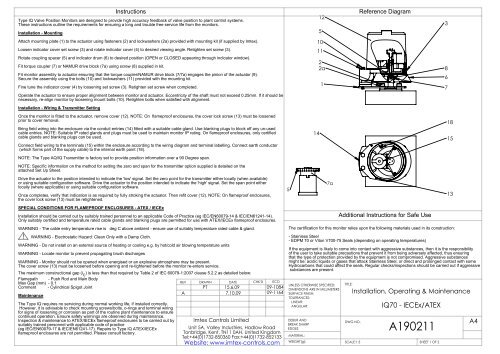
Instructions<br />
Type IQ Valve Position Monitors are designed to provide high accuracy feedback of valve position to plant control systems.<br />
These instructions outline the requirements for ensuring a long and trouble free service life from the monitors.<br />
Installation - Mounting<br />
Attach mounting plate (1) to the actuator using fasteners (2) and lockwashers (2a) provided with mounting kit (if supplied by <strong>Imtex</strong>).<br />
Loosen indicator cover set screw (3) and rotate indicator cover (4) to desired viewing angle. Retighten set screw (3).<br />
Rotate coupling spacer (5) and indicator drum (6) to desired position (OPEN or CLOSED appearing through indicator window).<br />
Fit torque coupler (7) or NAMUR drive block (7a) using screw (8) supplied in kit.<br />
Fit monitor assembly to actuator ensuring that the torque coupler/NAMUR drive block (7/7a) engages the pinion of the actuator (9).<br />
Secure the assembly using the bolts (10) and lockwashers (11) provided with the mounting kit.<br />
Fine tune the indicator cover (4) by loosening set screw (3). Retighten set screw when completed.<br />
Operate the actuator to ensure proper alignment between monitor and actuator. Eccentricity of the shaft must not exceed 0.25mm. If it should be<br />
necessary, re-align monitor by loosening mount bolts (10). Retighten bolts when satisfied with alignment.<br />
Installation - Wiring & Transmitter Setting<br />
Once the monitor is fitted to the actuator, remove cover (12). NOTE: On flameproof enclosures, the cover lock screw (13) must be loosened<br />
prior to cover removal.<br />
Bring field wiring into the enclosure via the conduit entries (14) fitted with a suitable cable gland. Use blanking plugs to block off any un-used<br />
cable entries. NOTE: Suitable IP rated glands and plugs must be used to maintain monitor IP rating. On flameproof enclosures, only certified<br />
cable glands and blanking plugs can be used.<br />
Connect field wiring to the terminals (15) within the enclosure according to the wiring diagram and terminal labelling. Connect earth conductor<br />
(which forms part of the supply cable) to the internal earth point (18).<br />
NOTE: The Type AQ/IQ Transmitter is factory set to provide position information over a 90 Degree span.<br />
NOTE: Specific information on the method for setting the zero and span for the transmitter option supplied is detailed on the<br />
attached Set Up Sheet.<br />
Drive the actuator to the position intended to indicate the 'low' signal. Set the zero point for the transmitter either locally (when available)<br />
or using suitable configuration software. Drive the actuator to the position intended to indicate the 'high' signal. Set the span point either<br />
locally (where applicable) or using suitable configuration software.<br />
Once completes, verify that indication is as required by fully stroking the actuator. Then refit cover (12). NOTE: On flameproof enclosures,<br />
the cover lock screw (13) must be retightened.<br />
SPECIAL CONDITIONS FOR FLAMEPROOF ENCLOSURES - ATEX / IECEx<br />
Installation should be carried out by suitably trained personnel to an applicable Code of Practice (eg IEC/EN60079-14 & IEC/EN61241-14).<br />
Only suitably certified and temperature rated cable glands and blanking plugs are permitted for use with ATEX/IECEx flameproof enclosures.<br />
WARNING - The cable entry temperature rise is deg C above ambient - ensure use of suitably temperature rated cable & gland.<br />
! WARNING - Electrostatic Hazard: Clean Only with a Damp Cloth.<br />
WARNING - Do not install on an external source of heating or cooling e.g. by hot/cold air blowing temperature units<br />
WARNING - Locate monitor to prevent propagating brush discharges<br />
WARNING - Monitor should not be opened when energised or an explosive atmosphere may be present.<br />
The cover screw (13) must be loosened before opening and re-tightened before the monitor re-enters service.<br />
The maximum constructional gap (i C<br />
) is less than that required by Table 2 of IEC 60079-1:2007 clause 5.2.2 as detailed below:<br />
Flamepath - Push Rod and Main Body<br />
Max Gap (mm) - 0.1<br />
REV DRAWN<br />
DATE CHK'D ECO<br />
Comment - Cylindrical Spigot Joint<br />
PT 15.6.09<br />
09-1084<br />
A<br />
7.10.09 09-1164<br />
Maintenance<br />
The Type IQ requires no servicing during normal working life, if installed correctly.<br />
However, it is advisable to check mounting screws/bolts, o-rings and terminal wiring<br />
for signs of loosening or corrosion as part of the routine plant maintenance to ensure<br />
continued operation. Ensure safety warnings are observed during maintenance.<br />
Inspection & maintenance to ATEX/IECEx flameproof enclosures to be carried out by<br />
suitably trained personnel with applicable code of practice<br />
(eg IEC/EN60079-17 & IEC/EN61241-17). Repairs to Type IQ ATEX/IECEx<br />
flameproof enclosures are not permitted. Please consult factory.<br />
<strong>Imtex</strong> <strong>Controls</strong> Limited<br />
Unit 5A, Valley Industries, Hadlow Road<br />
Tonbridge, Kent, TN11 0AH. United Kingdom<br />
Tel:+44(0)1732-850360 Fax:+44(0)1732-852133<br />
Website: www.imtex-controls.com<br />
5<br />
12<br />
5<br />
10<br />
11<br />
14<br />
2<br />
2a<br />
1<br />
7a<br />
UNLESS OTHERWISE SPECIFIED:<br />
DIMENSIONS ARE IN MILLIMETERS<br />
SURFACE FINISH:<br />
TOLERANCES:<br />
LINEAR:<br />
ANGULAR:<br />
DEBUR AND<br />
BREAK SHARP<br />
EDGES<br />
MATERIAL:<br />
WEIGHT(g):<br />
TITLE:<br />
DWG NO.<br />
Reference Diagram<br />
Additional Instructions for Safe Use<br />
The certification for this monitor relies upon the following materials used in its construction:<br />
- Stainless Steel<br />
- EDPM 70 or Viton V700-75 Seals (depending on operating temperatures)<br />
If the equipment is likely to come into contact with aggressive substances, then it is the responsibility<br />
of the user to take suitable precautions that prevent it from being adversely affected, thus ensuring<br />
that the type of protection provided by the equipment is not compromised. Aggressive substances<br />
might be: acidic liquids or gases that attack Stainless Steel, or direct and prolonged contact with some<br />
Hydrocarbons that could affect the seals. Regular checks/inspections should be carried out if aggressive<br />
substances are present.<br />
<strong>A190211</strong><br />
SCALE:1:5 SHEET 1 OF 2<br />
3<br />
8<br />
6<br />
7<br />
18<br />
15<br />
13<br />
Installation, Operating & Maintenance<br />
IQ70 - IECEx/ATEX<br />
A4
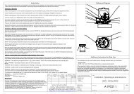
Wiring Diagrams and Operating Data<br />
MONITOR - TRANSMITTER -<br />
AQ/IQ70<br />
+<br />
-<br />
CONDUIT<br />
ENTRIES<br />
AQ/IQ70 - Analogue/Digital Transmitter<br />
Supply Voltage: 8 to 30VDC<br />
Internal Consumption: 25mW to 0.8W<br />
Voltage Drop: 8VDC<br />
Warm Up Time: 5 min<br />
Comms Link: Loop<br />
Signal / Noise Ratio: min 60 dB<br />
Min Response Time: 0.33 s<br />
Calibration Temp: +20 to +28 Deg C<br />
Op Temp Range: -40 to +60 Deg C<br />
Referenced Standards<br />
The following standards have been referred to in<br />
these instructions and are applicable to the use<br />
of this product when used in an environment<br />
where an explosive atmosphere may be present:<br />
IEC 60079-0:2007 5th Ed<br />
IEC60079-1:2007 6th Ed<br />
IEC 61241-1:2004 1st Ed<br />
EN60079-0:2006<br />
EN60079-1:2007<br />
EN61241-0:2006<br />
EN61241-1:2004<br />
Cable Entries<br />
The number and type of cable entry on the Monitor can be determined by reference<br />
to the 6th digit of the monitor part number. For example, in part number -<br />
IQ16S5SR<br />
the sixth digit is a '5' which corresponds to the monitor having 2 off M20 x 1.5 cable entry.<br />
Refer to table below for details.<br />
DIGIT<br />
5<br />
6<br />
8<br />
9<br />
B<br />
C<br />
CABLE ENTRY GUIDE<br />
ENTRIES SUPPLIED<br />
(2) M20 x 1.5<br />
(3) M20 x 1.5<br />
(1) 3/4" NPT (central entry)<br />
(1) 1/2" NPT (offset entry)<br />
(1) 3/4" NPT (central entry)<br />
(2) 1/2" NPT (offset entry)<br />
(2) 1/2" NPT<br />
(3) 1/2" NPT<br />
NPT Threads conform to ANSI/ASME B1.20.1 and shall be made up wrench tight<br />
Metric Thread tolerance to ISO 965-1 and ISO 965-3<br />
Product Markings<br />
The label on the monitor should be as below:<br />
TYPE IQ<br />
Valve Position Monitor<br />
IEC CERTIFICATE NO: IECEx SIR 08.0099X<br />
ATEX CERTIFICATE NO: SIRA 08ATEX 1266X<br />
Model: IQ<br />
Serial:<br />
MAX PERMISSIBLE POWER DISSIPATION WITHIN ENCLOSURE:<br />
WATTS<br />
88.86<br />
II 2 GD<br />
0518<br />
Exd IIC T6 Tamb = -40 C to +40 C Gb & Ex tb IIIC T85 C Db IP6X<br />
Exd IIC T6 Tamb = -40 C to +60 C Gb & Ex tb IIIC T85 C Db IP6X<br />
Exd IIC T4 Tamb = -15 C to +80 C Gb & Ex tb IIIC T135 C Db IP6X<br />
O<br />
WARNING: THE CABLE ENTRY TEMP. RISE IS C ABOVE AMBIENT AT<br />
MAX POWER. ENSURE USE OF SUITABLY RATED CABLE & GLAND<br />
WARNING: DO NOT OPEN WHEN ENERGISED OR WHEN AN<br />
EXPLOSIVE ATMOSPHERE MAY BE PRESENT.<br />
! Warning: Electrostatic Hazard - Clean Only with Damp Cloth<br />
Tonbridge - TN11 0AH - UK<br />
www.imtex-controls.com<br />
REV<br />
DRAWN<br />
DATE<br />
CHK'D ECO<br />
PT 15.6.09<br />
09-1084<br />
A 7.10.09 09-1164<br />
UNLESS OTHERWISE SPECIFIED:<br />
DIMENSIONS ARE IN MILLIMETERS<br />
SURFACE FINISH:<br />
TOLERANCES:<br />
LINEAR:<br />
ANGULAR:<br />
TITLE:<br />
Installation, Operating & Maintenance<br />
IQ70 - IECEx/ATEX<br />
This private & confidential drawing is the property<br />
of <strong>Imtex</strong> <strong>Controls</strong> Limited, Tonbridge, UK and cannot<br />
be copied or reproduced without the express<br />
written permission of the Company.<br />
<strong>Imtex</strong> <strong>Controls</strong> Limited<br />
Unit 5A, Valley Industries, Hadlow Road<br />
Tonbridge, Kent, TN11 0AH. United Kingdom<br />
Tel:+44(0)1732-850360 Fax:+44(0)1732-852133<br />
Website: www.imtex-controls.com<br />
DEBUR AND<br />
BREAK SHARP<br />
EDGES<br />
MATERIAL:<br />
WEIGHT(g):<br />
DWG NO.<br />
<strong>A190211</strong><br />
SCALE:1:5 SHEET 2 OF 2<br />
A4