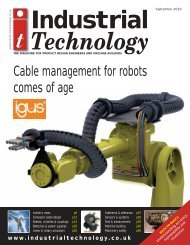
IT Jan 2008 - Industrial Technology Magazine
IT Jan 2008 - Industrial Technology Magazine
IT Jan 2008 - Industrial Technology Magazine

You also want an ePaper? Increase the reach of your titles
YUMPU automatically turns print PDFs into web optimized ePapers that Google loves.
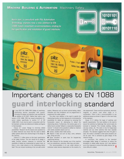
MACHINE BUILDING & AUTOMATION<br />
Machinery Safety<br />
Kevin Ives, a consultant with Pilz Automation<br />
<strong>Technology</strong>, explains how a new addition to EN<br />
1088 makes important recommendations relating to<br />
the specification and installation of guard interlocks<br />
Important changes to EN 1088<br />
guard interlocking standard<br />
In July 2007 EN 1088:1995 (Safety of machinery.<br />
Interlocking devices associated with guards.<br />
Principles for design and selection) was amended by<br />
the addition of A1:2007. Rather than write a new<br />
version of EN 1088, CEN has issued amendment A1,<br />
which relates specifically to section 5.7 of EN<br />
1088:1995. It can only be used in conjunction with the<br />
full standard, as there are references to tables and figures<br />
in that standard.<br />
Clause 5.7 covers ‘Design to minimise defeat<br />
possibilities’. Research into the reasons why operators try<br />
to defeat interlocks has shown that the need to defeat<br />
safety systems stems from shortcomings in the design of<br />
the machine.<br />
Clause 5.7.1 offers advice on the basic specification<br />
of the safety function. The aim should be to design a<br />
safety function wherein measures to minimise the<br />
possibility of defeat are implemented at system level, so<br />
there is not a total reliance on the interlocking device<br />
itself. This can include monitoring in the non-safe control<br />
system. Measures such as forced cyclical testing, status<br />
indication and time limitations can be programmed to<br />
supplement the safety system.<br />
The other main addition is the need to specify the<br />
interlocking function so that measures for minimising the<br />
possibilities for defeat are achieved by removing the<br />
foreseeable reason for attempting to defeat the<br />
interlocking device. Furthermore, this section goes on to<br />
define how to combat “defeat in a reasonably foreseeable<br />
manner”. It should not be possible to defeat an interlock<br />
with readily available objects such as:<br />
● Screws, needles sheet metal pieces;<br />
● Objects in daily use such as keys, coins, adhesive<br />
tape, string and wire;<br />
● Spare actuators or spare keys for trapped-key<br />
interlocking devices;<br />
● Tools required for the intended use of the machine<br />
such as screwdrivers, wrenches, Allen keys and pliers.<br />
The recommendation is to use coded devices or<br />
individual coded devices (dependant on the results of a<br />
risk assessment). These could be mechanical, electrical,<br />
magnetic or optical, used either singly or in<br />
combination. There is also a recommendation to use<br />
additional sensors as shown in figure 4 in the main body<br />
of the standard.<br />
Clause 5.7.2 defines the types of switches and<br />
specific requirements. The main addition is the need to<br />
secure the switches by fastenings that cannot easily be<br />
removed or loosened. This includes welding, riveting,<br />
one-way screws, etc. The same is true for tongue-type<br />
switches and any other switches that have separate<br />
actuators. The standard suggests that when the gate is<br />
open, the switch is shielded so that spare actuators can<br />
not be used. This is achieved by good design of the<br />
interlock fixings.<br />
In conclusion, this addition to the standard<br />
encourages better design of machinery to reduce the<br />
temptation to defeat safety devices, but it also tightens<br />
up on the measures to ensure that safety devices are<br />
more difficult to defeat.<br />
50<br />
INDUSTRIAL TECHNOLOGY • <strong>Jan</strong>uary <strong>2008</strong>