GFC240 Flow Computer With 4-20 mA Input - Flowmeters
GFC240 Flow Computer With 4-20 mA Input - Flowmeters
GFC240 Flow Computer With 4-20 mA Input - Flowmeters

You also want an ePaper? Increase the reach of your titles
YUMPU automatically turns print PDFs into web optimized ePapers that Google loves.
<strong>GFC240</strong><br />
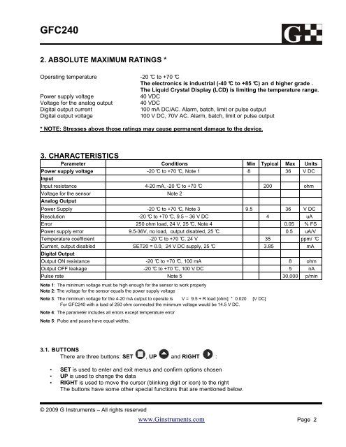
2. ABSOLUTE MAXIMUM RATINGS *<br />
Operating temperature -<strong>20</strong> °C to +70 °C<br />
The electronics is industrial (-40 °C to +85 °C) an d higher grade .<br />
The Liquid Crystal Display (LCD) is limiting the temperature range.<br />
Power supply voltage<br />
40 VDC<br />
Voltage for the analog output 40 VDC<br />
Digital output current<br />
100 <strong>mA</strong> DC/AC. Alarm, batch, limit or pulse output<br />
Digital output voltage<br />
100 V DC, 70V AC. Alarm, batch, limit or pulse output<br />
* NOTE: Stresses above those ratings may cause permanent damage to the device.<br />
3. CHARACTERISTICS<br />
Parameter Conditions Min Typical Max Units<br />
Power supply voltage -<strong>20</strong> °C to +70 °C, Note 1 8 36 V DC<br />
<strong>Input</strong><br />
<strong>Input</strong> resistance 4-<strong>20</strong> <strong>mA</strong>, -<strong>20</strong> °C to +70 °C <strong>20</strong>0 ohm<br />
Voltage for the sensor Note 2<br />
Analog Output<br />
Power Supply -<strong>20</strong> °C to +70 °C, Note 3 9.5 36 V DC<br />
Resolution -<strong>20</strong> °C to +70 °C, 9.5 – 36 V DC 4 uA<br />
Error 250 ohm load, 24 V, 25 °C, Note 4 0.05 % FS<br />
Power supply error 9.5-36V, no load, output disabled, 25 °C 0.5 uA/V<br />
Temperature coefficient -<strong>20</strong> °C to +70 °C, 24 V 35 ppm/ °C<br />
Current, output disabled SET<strong>20</strong> = 0.0, 24 V DC supply, 25 °C 3.85 <strong>mA</strong><br />
Digital Output<br />
Output ON resistance -<strong>20</strong> °C to +70 °C, 100 <strong>mA</strong> 8 ohm<br />
Output OFF leakage -<strong>20</strong> °C to +70 °C, 100 V DC 5 nA<br />
Pulse rate Note 5 30,000 p/min<br />
Note 1: The minimum voltage must be high enough for the sensor to work properly<br />
Note 2: The voltage for the sensor equals the power supply voltage<br />
Note 3: The minimum voltage for the 4-<strong>20</strong> <strong>mA</strong> output to operate is V = 9.5 + R load [ohm] * 0.0<strong>20</strong> [V DC]<br />
For <strong>GFC240</strong> with a load of 250 ohm connected the minimum voltage would be 14.5 V DC.<br />
Note 4: The parameter includes all errors except temperature error<br />
Note 5: Pulse and pause have equal widths.<br />
3.1. BUTTONS<br />
There are three buttons: SET , UP and RIGHT :<br />
• SET is used to enter and exit menus and confirm options chosen<br />
• UP is used to change the data<br />
• RIGHT is used to move the cursor (blinking digit or icon) to the right<br />
The buttons have some other special functions that are mentioned below.<br />
© <strong>20</strong>09 G Instruments – All rights reserved<br />
www.Ginstruments.com Page 2