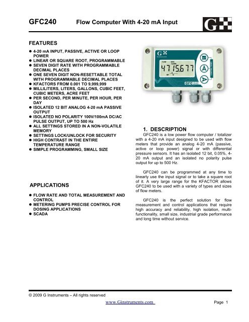
GFC240 Flow Computer With 4-20 mA Input - Flowmeters
GFC240 Flow Computer With 4-20 mA Input - Flowmeters
GFC240 Flow Computer With 4-20 mA Input - Flowmeters

You also want an ePaper? Increase the reach of your titles
YUMPU automatically turns print PDFs into web optimized ePapers that Google loves.
<strong>GFC240</strong><br />
<strong>Flow</strong> <strong>Computer</strong> <strong>With</strong> 4-<strong>20</strong> <strong>mA</strong> <strong>Input</strong><br />
FEATURES<br />
4-<strong>20</strong> <strong>mA</strong> INPUT, PASSIVE, ACTIVE OR LOOP<br />
POWER<br />
LINEAR OR SQUARE ROOT, PROGRAMMABLE<br />
SEVEN DIGIT RATE WITH PROGRAMMABLE<br />
DECIMAL PLACES<br />
ONE SEVEN DIGIT NON-RESETTABLE TOTAL<br />
WITH PROGRAMMABLE DECIMAL PLACES<br />
KFACTORS FROM 0.001 TO 9,999,999<br />
MILLILITERS, LITERS, GALLONS, CUBIC FEET,<br />
CUBIC METERS, ACRE FEET<br />
PER SECOND, PER MINUTE, PER HOUR, PER<br />
DAY<br />
ISOLATED 12 BIT ANALOG 4-<strong>20</strong> <strong>mA</strong> PASSIVE<br />
OUTPUT<br />
ISOLATED NO POLARITY 100V/100<strong>mA</strong> DC/AC<br />
PULSE OUTPUT, UP TO 500 Hz<br />
ALL SETTINGS STORED IN A NON-VOLATILE<br />
MEMORY<br />
SETTINGS LOCK/UNLOCK FOR SECURITY<br />
HIGH CONTRAST IN THE ENTIRE<br />
TEMPERATURE RANGE<br />
SIMPLE PROGRAMMING, SMALL SIZE<br />
APPLICATIONS<br />
FLOW RATE AND TOTAL MEASUREMENT AND<br />
CONTROL<br />
METERING PUMPS PRECISE CONTROL FOR<br />
DOSING APPLICATIONS<br />
SCADA<br />
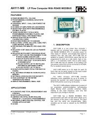
1. DESCRIPTION<br />
<strong>GFC240</strong> is a low power flow computer / totalizer<br />
with a 4-<strong>20</strong> <strong>mA</strong> input designed to be used with flow<br />
meters that provide an analog 4-<strong>20</strong> <strong>mA</strong> (passive,<br />
active or loop power) signal or with differential<br />
pressure sensors. It has an isolated 12 bit, 0.05%, 4-<br />
<strong>20</strong> <strong>mA</strong> output and an isolated no polarity pulse<br />
output for up to 500 Hz.<br />
<strong>GFC240</strong> can be programmed at any time to<br />
linearly use the input signal or to take a square root<br />
of it. A very large range for the KFACTOR allows<br />
<strong>GFC240</strong> to be used with a variety of types and sizes<br />
of flow meters.<br />
<strong>GFC240</strong> is the perfect solution for flow<br />
measurement and control applications that require<br />
high accuracy and reliability, high isolation, multifunctionality,<br />
small size, industrial grade performance<br />
and long time without service.<br />
© <strong>20</strong>09 G Instruments – All rights reserved<br />
www.Ginstruments.com Page 1
<strong>GFC240</strong><br />
2. ABSOLUTE MAXIMUM RATINGS *<br />
Operating temperature -<strong>20</strong> °C to +70 °C<br />
The electronics is industrial (-40 °C to +85 °C) an d higher grade .<br />
The Liquid Crystal Display (LCD) is limiting the temperature range.<br />
Power supply voltage<br />
40 VDC<br />
Voltage for the analog output 40 VDC<br />
Digital output current<br />
100 <strong>mA</strong> DC/AC. Alarm, batch, limit or pulse output<br />
Digital output voltage<br />
100 V DC, 70V AC. Alarm, batch, limit or pulse output<br />
* NOTE: Stresses above those ratings may cause permanent damage to the device.<br />
3. CHARACTERISTICS<br />
Parameter Conditions Min Typical Max Units<br />
Power supply voltage -<strong>20</strong> °C to +70 °C, Note 1 8 36 V DC<br />
<strong>Input</strong><br />
<strong>Input</strong> resistance 4-<strong>20</strong> <strong>mA</strong>, -<strong>20</strong> °C to +70 °C <strong>20</strong>0 ohm<br />
Voltage for the sensor Note 2<br />
Analog Output<br />
Power Supply -<strong>20</strong> °C to +70 °C, Note 3 9.5 36 V DC<br />
Resolution -<strong>20</strong> °C to +70 °C, 9.5 – 36 V DC 4 uA<br />
Error 250 ohm load, 24 V, 25 °C, Note 4 0.05 % FS<br />
Power supply error 9.5-36V, no load, output disabled, 25 °C 0.5 uA/V<br />
Temperature coefficient -<strong>20</strong> °C to +70 °C, 24 V 35 ppm/ °C<br />
Current, output disabled SET<strong>20</strong> = 0.0, 24 V DC supply, 25 °C 3.85 <strong>mA</strong><br />
Digital Output<br />
Output ON resistance -<strong>20</strong> °C to +70 °C, 100 <strong>mA</strong> 8 ohm<br />
Output OFF leakage -<strong>20</strong> °C to +70 °C, 100 V DC 5 nA<br />
Pulse rate Note 5 30,000 p/min<br />
Note 1: The minimum voltage must be high enough for the sensor to work properly<br />
Note 2: The voltage for the sensor equals the power supply voltage<br />
Note 3: The minimum voltage for the 4-<strong>20</strong> <strong>mA</strong> output to operate is V = 9.5 + R load [ohm] * 0.0<strong>20</strong> [V DC]<br />
For <strong>GFC240</strong> with a load of 250 ohm connected the minimum voltage would be 14.5 V DC.<br />
Note 4: The parameter includes all errors except temperature error<br />
Note 5: Pulse and pause have equal widths.<br />
3.1. BUTTONS<br />
There are three buttons: SET , UP and RIGHT :<br />
• SET is used to enter and exit menus and confirm options chosen<br />
• UP is used to change the data<br />
• RIGHT is used to move the cursor (blinking digit or icon) to the right<br />
The buttons have some other special functions that are mentioned below.<br />
© <strong>20</strong>09 G Instruments – All rights reserved<br />
www.Ginstruments.com Page 2
<strong>GFC240</strong><br />
There are two types of buttons accepted by the <strong>GFC240</strong> flow computer / totalizer:<br />
• Short is when the button is pressed and released in less than 0.5 second<br />
• Long is when it is kept pressed for more than 5 seconds<br />
• All other durations are ignored<br />
NOTE: The UP button will not change the value if the settings are locked.<br />
3.2. INPUTS<br />
<strong>GFC240</strong> has one 4-<strong>20</strong> <strong>mA</strong> input that can accept passive, active an loop power sensors.<br />
3.3. OUTPUTS<br />
<strong>GFC240</strong> has two isolated outputs:<br />
3.3.1. Analog output<br />
The isolated analog output is 4-<strong>20</strong> <strong>mA</strong>, two wire, loop power passive, 12 bit, with reverse polarity and<br />
surge protection, high accuracy and reliability. Using the SET<strong>20</strong> menu it can be programmed to<br />
represent the flow rate.<br />
SET<strong>20</strong> parameter means at what flow rate (in G/M) the output will be <strong>20</strong>.00 <strong>mA</strong>.<br />
3.3.2. Digital output<br />
The isolated digital output has no polarity, can work with 100V/100<strong>mA</strong> and is a pulse output only. It is<br />
intended for use with metering/dosing pumps, SCADA, PLCs and other devices. It can provide up to<br />
30 000 pulses per minute (500 Hz) with equal duration of the pulse and the pause.<br />
Example: You are adding chlorine or fertilizer to the water and have connected the control input of a<br />
pump to this pulse output. You program the “SETP” factor at 3.762 Gallons per pulse. The pump will<br />
produce one pulse every 3.762 gallons and add the chlorine or the fertilizer in an exact proportion to the<br />
water.<br />
3.4. DISPLAY<br />
The liquid crystal display (LCD) has 7 digits with 1, 2 or 3 decimal places and many icons.<br />
It shows rate, total and all the variables and options that can be set or programmed. The rate and the<br />
total have programmable auto, none, 1, 2 or 3 decimal places.<br />
<strong>GFC240</strong> software implements our latest proprietary algorithms for predictive / adaptive self-adjusting<br />
digital filtering of the rate. It provides exceptionally stable reading but in the same time very fast<br />
response to any change in the flow.<br />
A “FLOW” icon will always be displayed.<br />
When the display shows rate a “RATE” icon is displayed. If it shows total a “TOTAL” icon will be<br />
displayed.<br />
When the input is correct an “INP” (input) icon will be displayed. If the input current drops below about<br />
3.8 <strong>mA</strong> “no inP” (no input) will be displayed.<br />
© <strong>20</strong>09 G Instruments – All rights reserved<br />
www.Ginstruments.com Page 3
<strong>GFC240</strong><br />
Whenever the digital output is ON the pulse icon for the cause will be displayed.<br />
If the total on the LCD is allowed to be reset a “RESET” icon will be displayed.<br />
3.4.1. Volume and time units<br />
• Milliliters (mL), liters (L), gallons (G), cubic feet (CF), cubic meters (M 3 ) and acre feet (AF) per second<br />
(S), minute (M), hour (H) and day (D) are available.<br />
3.4.2. Normal mode<br />
Automatically after turning the power on or exiting a menu <strong>GFC240</strong> enters the normal mode.<br />
In this mode it can only display:<br />
• Rate<br />
• and total. Total reset can be enabled or disabled and the total is stored in a non-volatile memory every<br />
50 seconds or immediately when cleared.<br />
If the total is allowed to be reset the RESET icon is shown. Reseting a total is by using long RIGHT<br />
button.<br />
• Switching between rate and total is by using short UP button.<br />
3.4.3. Menus<br />
To enter the menus use long SET button in normal mode. About 5 seconds after pressing (and holding<br />
pressed) the SET button the first menu will appear on the LCD:<br />
• KFACTOR icon along with dP 1234 is shown and using UP button the decimal places for the<br />
KFACTOR can be programmed. This way a KFACTOR in the range from 0.001 to 9,999,999 can be<br />
entered. Use short SET to move to the next menu.<br />
• KFACTOR icon is shown and using UP and RIGHT the KFACTOR for the particular FLOW meter<br />
connected to the <strong>GFC240</strong> can be entered.<br />
While in this menu all the settings can be locked/unlocked. Use RIGHT button to move the cursor to the<br />
right most digit and then use long SET.<br />
• Using short UP lock/unlock the settings. Then use short SET to go back to KFACTOR menu<br />
• If the settings are locked then they can only be viewed but not changed.<br />
From the KFACTOR menu use short SET to enter the next menu. NOTE that the computer will not<br />
accept zero for the KFACTOR.<br />
• In the input type menu use short UP to change between Lin and Sqrt.<br />
If Lin is chosen <strong>GFC240</strong> will calculate the flow rate according to the following formula:<br />
<strong>Flow</strong> Rate = <strong>Input</strong> * <strong>20</strong> <strong>mA</strong> value / KFACTOR<br />
If Sqrt has been chosen then <strong>GFC240</strong> will use:<br />
<strong>Flow</strong> Rate = sqrt(<strong>Input</strong> * <strong>20</strong> <strong>mA</strong> value) * KFACTOR<br />
© <strong>20</strong>09 G Instruments – All rights reserved<br />
www.Ginstruments.com Page 4
<strong>GFC240</strong><br />
= “<strong>Input</strong>” is the normalized value of the input from 0.0 to 1.0, so 4 <strong>mA</strong> is 0.0, <strong>20</strong> <strong>mA</strong> is 1.0<br />
= “<strong>20</strong> <strong>mA</strong> value” is a value in engineering units that corresponds to an input of <strong>20</strong> <strong>mA</strong><br />
= “sqrt” means square root<br />
= KFACTOR is a coefficient of proportion corresponding to the physics and specifics of the particular<br />
flow meter<br />
Press short SET to move to “100% value” menu.<br />
• In the “100% value” menu program the value in engineering units that corresponds to a <strong>20</strong> <strong>mA</strong> input.<br />
Press short SET to move to CUt oFF menu.<br />
• In that menu a cut off from 0.0% to 9.9 % can be programmed. This feature is very useful because the<br />
input is analog and there always be some small mismatch of the real value of the input 4 <strong>mA</strong> and the<br />
value that <strong>GFC240</strong> considers to be a 4 <strong>mA</strong> signal. The cut off can also be used to cut some very low<br />
flow from leaks or jitter of the liquid. Press short SET to move to SET<strong>20</strong> menu.<br />
• In the SET<strong>20</strong> menu program the flow rate in G/M at which you want the analog output to be <strong>20</strong>.00 <strong>mA</strong>.<br />
Analog output will be 4.00 <strong>mA</strong> at 0.0 G/M. If SET<strong>20</strong> = 0.0 the analog output will stay about 3.85 <strong>mA</strong> and<br />
will not change with the rate. Press short SET to move to “volume units” menu.<br />
• In the “volume units” (vU) menu use UP to choose the volume units among mL, L, G, CF, M 3 and AF.<br />
Press short SET to move to the “time units” menu<br />
• In the “time units” (tU) menu use UP to choose the time units among S, M, H and D. Press short SET<br />
to move to the SETP dP (decimal places) menu.<br />
• SETP icon along with dP 1234 will appear and using UP button the decimal places for SETP can be<br />
programmed. Use short SET to move to SETP menu.<br />
• The value for SETP must be in GALLONS PER PULSE and the computer will not accept zero for this<br />
setting.<br />
• Press short SET to move to the “Rate decimal Places” menu where using short UP auto, none, 1, 2, or 3<br />
decimal places for the flow rate can be programmed.<br />
• Press short SET to move to the “Total decimal Places” menu where using short UP auto, none, 1, 2, or 3<br />
decimal places for all totals can be programmed.<br />
• Press short SET to move to the Total Reset enable/disable menu. In this menu using UP button the<br />
total reset can be enabled or disabled.<br />
If enabled and <strong>GFC240</strong> is in normal mode displaying total the RESET icon will also be displayed and<br />
long RIGHT will clear the total.<br />
Because this menu is the last one pressing a long SET will move the computer to the LOCK menu.<br />
Use UP to lock the settings and press short SET to go back to Total Reset enable menu. General<br />
practice would be the settings to be unlocked at the first (KFACTOR) menu, then changed and locked<br />
again before exiting at the last menu. Press short SET to exit the last menu. After a couple of seconds<br />
during which all the settings are being checked, validated and stored into the non-volatile<br />
memory, the computer will move to the normal mode.<br />
© <strong>20</strong>09 G Instruments – All rights reserved<br />
www.Ginstruments.com Page 5
<strong>GFC240</strong><br />
NOTE: There is a time out built-in the software that will reset the computer and force it to<br />
the normal mode WITHOUT saving any changes made in any of the menus. The changes<br />
will only be saved after exiting the Total A Reset enable menu by pressing short SET.<br />
NOTE: During menus the computer continues to measure and calculate rate and total and<br />
control the outputs so no total will be lost. But changing for an instance the KFACTOR<br />
will invalidate the total accumulated. So it would be the user's responsibility to take<br />
appropriate actions after changing the settings like reseting the totals or leaving them as<br />
they were, for an instance.<br />
3.5. Checking the LCD<br />
All the icons of the LCD can be checked by pressing and holding the RIGHT button during turning the<br />
power supply on or after exiting the last menu. Releasing the button will allow the computer to go to<br />
normal mode.<br />
3.6. Removing the power<br />
The total is stored in the non-volatile memory every 50 second.<br />
Before removing the power make sure that there was no flow for the last minute.<br />
© <strong>20</strong>09 G Instruments – All rights reserved<br />
www.Ginstruments.com Page 6
<strong>GFC240</strong><br />
4. MENU DIAGRAM<br />
The menu diagram for <strong>GFC240</strong> flow computer / totalizer is shown below.<br />
NORMAL MODE<br />
LONG<br />
KFACTOR DP<br />
KFACTOR<br />
LIN / SQRT<br />
LONG*<br />
SETP<br />
LOCK/UNLOCK<br />
100% VALUE<br />
SETP DP<br />
RATE DP<br />
CUT OFF<br />
TIME UNITS<br />
TOTAL DP<br />
Total Reset<br />
Enable<br />
LONG<br />
SET<strong>20</strong><br />
VOL. UNITS<br />
LOCK<br />
LONG* - PRESSING LONG SET BUTTON WHEN<br />
THE CURSOR IS AT THE RIGHT MOST DIGIT<br />
© <strong>20</strong>09 G Instruments – All rights reserved<br />
www.Ginstruments.com Page 7
<strong>GFC240</strong><br />
5. APPLICATION<br />
5.1. ELECTRICAL<br />
The wiring diagram is shown below.<br />
NOTE: There is no isolation between the sensor input and the power supply. Terminals 2 and 9<br />
are shorted inside the device. It is the user's responsibility to consider this fact and implement<br />
appropriate wiring in the particular user's application.<br />
1 – Power supply plus<br />
2 – Power supply minus<br />
5, 6 – Digital output, no polarity<br />
7 – Sensor plus<br />
8 – Sensor signal<br />
9 – Sensor minus<br />
10 – Analog output plus<br />
11 – Analog output minus<br />
1 2 3 4 5 6 7 8 9 10 11<br />
8 – 36 V DC<br />
- +<br />
SCADA<br />
4-<strong>20</strong> <strong>mA</strong> - +<br />
Metering Pump<br />
SENSOR<br />
© <strong>20</strong>09 G Instruments – All rights reserved<br />
www.Ginstruments.com Page 8
<strong>GFC240</strong><br />
5.1.1. Wiring<br />
5.1.1.1. Passive sensor, loop power<br />
+ S -<br />
<strong>GFC240</strong> powers the sensor and measure its current using 2 wires.<br />
+ -<br />
SENSOR<br />
5.1.1.2. Two wire active sensor<br />
+ S -<br />
The sensor has its own power and <strong>GFC240</strong> only measures its signal (current).<br />
+ -<br />
SENSOR<br />
5.1.1.3. Three wire connection<br />
+ S -<br />
POWER<br />
+<br />
SIGNAL<br />
COMMON<br />
<strong>GFC240</strong> powers the sensor and measures its signal (current). The sensor must be<br />
sourcing current out of “signal”.<br />
SENSOR<br />
© <strong>20</strong>09 G Instruments – All rights reserved<br />
www.Ginstruments.com Page 9
<strong>GFC240</strong><br />
5.2. MECHANICAL<br />
Mounting <strong>GFC240</strong> on a wall requires an area of 1<strong>20</strong> x 65 mm (4.73 x 2.56 inch) and two screws:<br />
52.0 mm (2.047”)<br />
87.0 mm (3.425”)<br />
NOTE: The cable grips and the cables need additional space<br />
6. ORDERING<br />
For ordering please use the following G Instruments part numbers:<br />
Description<br />
G Instruments PN<br />
<strong>GFC240</strong> flow computer without power supply (external 8 – 36 V DC required) 30195<br />
<strong>GFC240</strong> flow computer with GPS115 (115 VAC power supply) 30196<br />
<strong>GFC240</strong> flow computer with GPS2<strong>20</strong> (2<strong>20</strong> VAC power supply) 30197<br />
<strong>GFC240</strong> flow computer with GPS122 (85-264 VAC power supply) 30240<br />
© <strong>20</strong>09 G Instruments – All rights reserved<br />
www.Ginstruments.com Page 10
<strong>GFC240</strong><br />
IMPORTANT NOTICE<br />
G Instruments reserves the right to make corrections, modifications, enhancements, improvements, and other<br />
changes to its products at any time without notice.<br />
Customers should obtain the latest relevant information before placing orders and should verify that such<br />
information is current and complete.<br />
G Instruments does not assume any liability arising from the use of any device or circuit described herein, nor does<br />
it convey any license under its patent rights or the rights of others.<br />
Customers are responsible for their products and applications using G Instruments devices. To minimize the risks<br />
associated with customer products and applications, customers should provide adequate design and operating safeguards.<br />
G Instruments products are not authorized for use as critical components in life support devices or systems without<br />
express written approval of G Instruments.<br />
Trademarks and registered trademarks are the property of their respective owners.<br />
© <strong>20</strong>09 G Instruments – All rights reserved<br />
www.Ginstruments.com Page 11