instruction manual - Toplight - Safety Lamp of Houston Inc.
instruction manual - Toplight - Safety Lamp of Houston Inc.
instruction manual - Toplight - Safety Lamp of Houston Inc.

You also want an ePaper? Increase the reach of your titles
YUMPU automatically turns print PDFs into web optimized ePapers that Google loves.
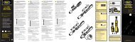
Toplite Portable Searchlight TL-9050T3 Spotlight & TL-9055T3 Floodlight<br />
Operation and Maintenance Instructions<br />
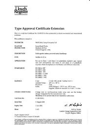
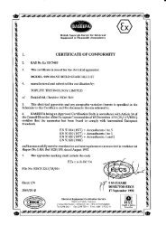
Certification<br />
Code: EEx e m ib IIC T3 Certification: BASEEFA No. Ex 92 C 3405<br />
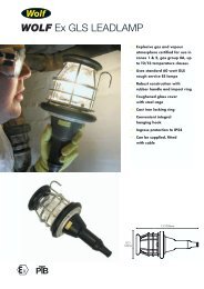
Use <strong>of</strong> Toplite Searchlight in Hazardous Areas<br />
• The Toplite TL-9050T3 Spotlight and TL-9055T3 Floodlight are for use in potentially explosive gases, vapours and mists,<br />
zones 1 and 2. Applicable standards: EN50014:1977, EN50019:1977, EN50020:1977, EN50028:1987. The Toplite is not approved<br />
for use in zone 0.<br />
• Users should consult BS 5345:Part 1:1989 or IEC 79-10 'Code <strong>of</strong> practice for the selection, installation and maintenance <strong>of</strong><br />
electrical apparatus for use in potentially explosive atmospheres', or national equivalent.<br />
• Permissible hazardous area ambient: -20 o C to +40 o C.<br />
• Copies <strong>of</strong> the Toplite Approval Certificate are available on request.<br />
• Ingress protection for the Toplite Handheld Searchlight: IP67 to EN60529:1992.<br />
• Heavily soiled lamps must not be immersed in water or exposed to high pressure jets for cleaning.<br />
• The Toplite body is anti-static.<br />
• The Toplite is CE marked in compliance with the EMC directive, a declaration <strong>of</strong> conformity is available on request.<br />
• <strong>Lamp</strong>s must not be charged or opened in hazardous areas. Charging and maintenance must be carried out in a safe area.<br />
• A damaged lamp should be withdrawn, examined and repaired before being put back into service. Maintenance and repair must<br />
be carried out by a competent technician or electrician, familiar with certified electrical apparatus, in accordance with these<br />
maintenance <strong>instruction</strong>s and using factory supplied spare parts only. Modifications to the Toplite are not permitted.<br />
Operation<br />
To use. Charge lamp before use. Switch operation positions: up:- high power middle:- <strong>of</strong>f down:- low power<br />
Mode <strong>of</strong> Operation. The Toplite control circuit assembly manages the operation and charging <strong>of</strong> the lamp, it also shows available<br />
battery duration by coloured indicator state. At the end <strong>of</strong> a discharge, the lamp will automatically switch down to walk-out mode and<br />
run for approximately 10 minutes before automatic cut-<strong>of</strong>f. The indication cycle is shown below:<br />
mode <strong>of</strong> use<br />
main discharge<br />
indicator state<br />
Discharge Indication Sequence TL-9050T3 & TL9055T3<br />
duration <strong>of</strong> colour state (approximate)<br />
TL-9050T3 (50 watt)<br />
TL-9055T3 (35 watt)<br />
high power low power high power low power<br />
green 30 mins 60 mins 45 mins 90 mins<br />
amber 30 mins 60 mins 45 mins 90 mins<br />
walk-out mode red ** 10 mins approx. 10 mins approx.<br />
Total duration 70 mins 130 mins 100 mins 190 mins<br />
** Note: On reaching red state, lamp automatically switches to low power and pulses every 15 seconds<br />
Discharge times may vary with the age <strong>of</strong> the battery<br />
Charging<br />
To Charge the Toplite. Only charge the Toplite T3 with the specified Toplite T3 Charger. Plug the charger into a mains socket.<br />
Remove the charging socket protective cover at the rear <strong>of</strong> the handle on the Toplite body. Insert the charging plug into the socket,<br />
the charge indicator on the Toplite will start to flash to confirm charging. If the indicator does not start to flash, either the charging<br />
plug is not correctly fitted or the Toplite is already charged. Replace charging socket protective cover after charging.<br />
Toplite State <strong>of</strong> Charge Indicator. To ensure correct calibration <strong>of</strong> the state <strong>of</strong> charge indicator, users are advised that once in<br />
e very 20 charge/discharge cycles, the Toplite should be fully discharged, past the walk-out mode, until it automatically cuts-<strong>of</strong>f.<br />
Toplite Power Failure Mode. The Toplite can be charged with the operation switch in the on position, but the lamp will not<br />
illuminate. If power to the charger is then interrupted (i.e. if mains power fails) the Toplite will automatically illuminate.<br />
Toplite Over-Temperature Warning. The Toplite has a thermal sensor built into the battery pack, fitted to protect against<br />
excessive heat rise during charging or discharging <strong>of</strong> the battery. In the unlikely event that the battery does exceed temperature<br />
limits, the Toplite system will shut down and the indicator will scroll through the three colour states. Allow the Toplite battery to cool<br />
for 30 minutes and resume use. If over-temperature problems persist, contact the supplier or manufacturer.<br />
Battery Care<br />
To ensure maximum capacity from the battery it is advisable to fully discharge and recharge twice every six months.
Toplite Chargers TL-9052T3 (UK), TL-9053T3 (EU) and TL-9054T3 (EU lead in, lead out)<br />
The Chargers are either ‘plug-top’ or ‘lead in, lead out’ style, for use on mains AC voltages <strong>of</strong> 230 Volts at 50-60Hz. Charging is<br />
fully automatic and takes approximately 16 hours, after which it steps down to a trickle charge state, allowing the lamp to be left on<br />
charge continuously. The Chargers are CE marked in compliance with the Low Voltage Directive and the EMC Directive, a<br />
declaration <strong>of</strong> conformity is available on request. The Toplite TL-9050T3 and TL-9055T3 <strong>Lamp</strong>s must only be charged with the<br />
specified Toplite Charger in a non-hazardous area. Do not use the Toplite Charger with any other type <strong>of</strong> rechargeable system.<br />
Maintenance<br />
Charging Indication Sequence TL-9050T3 & TL9055T3<br />
Indicator Colour State <strong>of</strong> charge (%)<br />
red flashing 0 - 45<br />
amber flashing 45 - 90<br />
green flashing 90 - 99<br />
green 100%<br />
Charging time for a fully discharged lamp is 16 hours; charging times may vary with the age <strong>of</strong> the battery<br />
Before working on the Toplite, ensure it is switched '<strong>of</strong>f'. Work should never be carried out with the switch in the 'on' position or<br />
with the Toplite connected to the Charger.<br />
To open the Toplite. Remove the retaining bolts and lens cover from the front <strong>of</strong> the lamp. Remove the toughened glass disc and<br />
flat seal. Remove the sealed beam unit; this may be a tight fit in the lamp cavity in the Toplite body moulding. In some cases the<br />
side <strong>of</strong> the Toplite body can be tapped in order to assist in the removal <strong>of</strong> the sealed beam unit. Note the orientation <strong>of</strong> the lamp for<br />
refitting. To replace the sealed beam unit, see <strong>instruction</strong>s below.<br />
To remove the Switch Assembly. Ensure the switch connector is disconnected. Remove the locking nut from the switch bush on<br />
the outside <strong>of</strong> the lamp. Remove the switch from the inside <strong>of</strong> the lamp; note orientation for correct refitting.<br />
To remove the State <strong>of</strong> Charge Indicator. This procedure will almost certainly result in damage to the components, users are<br />
strongly advised not to carry out such work unless it is considered essential. Ensure the indicator connector is disconnected.<br />
Remove the locking nut from the indicator bush on the inside <strong>of</strong> the Toplite. Pull the indicator housing through from the outside <strong>of</strong><br />
the lamp. Unscrew the white LED retainer ensuring that the legs <strong>of</strong> the LED are not strained. Pull the LED out <strong>of</strong> the indicator<br />
housing. The LED with leads and connector attached can now be removed through the inside <strong>of</strong> the Toplite.<br />
To carry out any further work the Chassis must be removed<br />
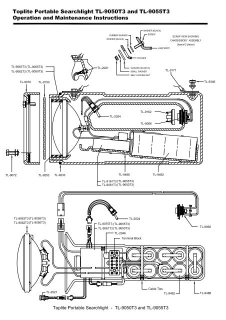
To remove the Chassis. Remove the two retaining nuts from the front flanges <strong>of</strong> the Chassis, use a hex key to prevent retaining<br />
screws from turning. Disconnect all connectors and withdraw the Chassis from the Toplite body. When re-assembling, check with<br />
diagram to ensure parts are assembled correctly, check that rubber seal is undamaged.<br />
To replace the Sealed Beam Unit. Loosen the two screws on the terminal block holding the yellow lamp wires. The wires can be<br />
removed and wires from a replacement sealed beam unit fitted and the screws tightened.<br />
To replace the Fuse. Loosen the two screws on the terminal block holding the Fuse. The Fuse can be removed and a<br />
replacement fitted and the screws tightened.<br />
To remove the control circuit assembly. Ensure that all connectors are disconnected and all wires from the terminal block to<br />
other components are removed. CAUTION, prevent the wires from the battery pack touching each other. Cut the tywrap<br />
holding the control circuit assembly in place and remove from the chassis. The refitting is the reverse procedure.<br />
To remove the Battery Pack. Ensure the connector from the battery pack to the control circuit assembly is disconnected. Cut the<br />
two tywraps holding the battery pack into the chassis. Loosen the two screws on the terminal block holding the wires from the<br />
battery pack, withdraw the wires. CAUTION, ensure the wires do not touch. The battery pack can now be removed from the<br />
chassis. The refitting <strong>of</strong> a new battery pack is the reverse procedure. Ensure the connecting wires are tightly clamped in the<br />
terminal block and the tywraps are replaced.<br />
Note: When the battery pack is disconnected from the control circuit assembly, the system is reset to zero capacity. The Toplite<br />
must be recharged before further use.<br />
The Toplite Battery is a Nickel Cadmium cell system, providing up to 1000 charge and discharge cycles. The pack is specifically<br />
designed to comply with the requirements <strong>of</strong> electrical equipment for use in potentially explosive atmospheres and must not be<br />
replaced with any non-Wolf component. For optimum performance and safety please observe the following:<br />
• Charge before first use Warning:<br />
• Recharge immediately when flat Do not incinerate or short circuit<br />
• Recharge every three months when in storage. Do not cut, crush or puncture<br />
• Dispose <strong>of</strong> battery via a licensed disposal agency Do not charge other than from a Wolf Charger<br />
Note: Dangerous goods regulations, hazardous materials regulations, restricted articles regulations<br />
The US Department <strong>of</strong> Transport, IATA and CAA declare these batteries as 'non-regulated'.<br />
The Wolf <strong>Safety</strong> <strong>Lamp</strong> Company have a policy <strong>of</strong> continuous product review and improvement, changes in design details may be<br />
made without prior notice.<br />
All performance values given have been attained under laboratory conditions, the user must regard these values as approximate.<br />
11-03-04 Issue 2
Spare Parts List for<br />
Toplite Portable Searchlight TL-9050T3 and TL-9055T3<br />
Part No.<br />
Description<br />
TL-9062T3<br />
Sealed Beam Assembly 50 watt (spot)<br />
TL-9063T3<br />
Sealed Beam Assembly 35 watt (flood)<br />
TL-9061T3<br />
Control Circuit Assembly 50 watt<br />
TL-9075T3<br />
Control Circuit Assembly 35 watt<br />
TL-2021<br />
State <strong>of</strong> Charge Indicator Assembly<br />
TL-2024<br />
Switch Assembly T3<br />
TL-2046<br />
Encapsulated 7 Amp Fuse<br />
TL-9066<br />
Charging Socket Assembly<br />
TL-9070<br />
Lens Cap Complete<br />
TL-9072 Retaining Bolt/Washer Set (4)<br />
TL-9150<br />
Lens (Toughened Glass)<br />
TL-9162<br />
Charging Socket Protective Cover<br />
TL-9171<br />
Shoulder Strap and Fittings<br />
TL-9233<br />
‘O’ Seal<br />
TL-9253<br />
Flat Seal<br />
TL-9346<br />
M8 x 12 mm Brass Bolts for Shoulder Strap<br />
TL-9488<br />
Chassis<br />
TL-9492<br />
Battery Assembly 4.3 Ah<br />
THE WOLF SAFETY LAMP COMPANY<br />
SAXON ROAD WORKS . SHEFFIELD S8 0YA . ENGLAND<br />
Tel: +44 (0)114 255 1051 Fax: +44 (0)114 255 7988<br />
Toplite Instructions 11 Sept 2000