Filter Design
Filter Design
Filter Design

Create successful ePaper yourself
Turn your PDF publications into a flip-book with our unique Google optimized e-Paper software.
Circuits 212 Lab<br />
Lab #6<br />
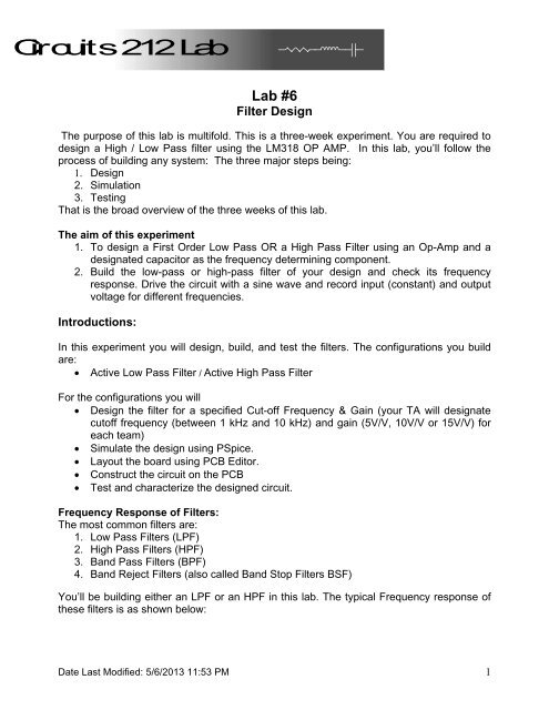
<strong>Filter</strong> <strong>Design</strong><br />
The purpose of this lab is multifold. This is a three-week experiment. You are required to<br />
design a High / Low Pass filter using the LM318 OP AMP. In this lab, you’ll follow the<br />
process of building any system: The three major steps being:<br />
1. <strong>Design</strong><br />
2. Simulation<br />
3. Testing<br />
That is the broad overview of the three weeks of this lab.<br />
The aim of this experiment<br />
1. To design a First Order Low Pass OR a High Pass <strong>Filter</strong> using an Op-Amp and a<br />
designated capacitor as the frequency determining component.<br />
2. Build the low-pass or high-pass filter of your design and check its frequency<br />
response. Drive the circuit with a sine wave and record input (constant) and output<br />
voltage for different frequencies.<br />
Introductions:<br />
In this experiment you will design, build, and test the filters. The configurations you build<br />
are:<br />
Active Low Pass <strong>Filter</strong> / Active High Pass <strong>Filter</strong><br />
For the configurations you will<br />
<strong>Design</strong> the filter for a specified Cut-off Frequency & Gain (your TA will designate<br />
cutoff frequency (between 1 kHz and 10 kHz) and gain (5V/V, 10V/V or 15V/V) for<br />
each team)<br />
Simulate the design using PSpice.<br />
Layout the board using PCB Editor.<br />
Construct the circuit on the PCB<br />
Test and characterize the designed circuit.<br />
Frequency Response of <strong>Filter</strong>s:<br />
The most common filters are:<br />
1. Low Pass <strong>Filter</strong>s (LPF)<br />
2. High Pass <strong>Filter</strong>s (HPF)<br />
3. Band Pass <strong>Filter</strong>s (BPF)<br />
4. Band Reject <strong>Filter</strong>s (also called Band Stop <strong>Filter</strong>s BSF)<br />
You’ll be building either an LPF or an HPF in this lab. The typical Frequency response of<br />
these filters is as shown below:<br />
Date Last Modified: 5/6/2013 11:53 PM 1
Components Required for the Lab:<br />
These are your design constraints for this Lab: You are required to use the LM318<br />
Operational Amplifier, and the 0.22uF capacitor as one of the two frequency determining<br />
components. All other resistor & capacitor values are determined by your design<br />
calculations, but you may only use standard value components in the EECS Shop.<br />
Standard Values will be discussed in the lab.<br />
Circuit Diagram:<br />
Your circuit configuration looks something like this:<br />
Low Pass<br />
Date Last Modified: 5/6/2013 11:53 PM 2
HIGH PASS<br />
Note that the op-amp is used in its non-inverting mode (the input is connected to pin 3).<br />
The resistor-capacitor configuration between the input and the op-amp's non-inverting<br />
input provides the desired filtering.<br />
Procedure:<br />
Week 1:<br />
1. <strong>Design</strong> a <strong>Filter</strong> for the given Cut-off Frequency and Gain. The Relevant Equations<br />
for both Low pass & High pass circuits are:<br />
Gain: = 1 + R F / R G<br />
Cut off Frequency = 1 / (2 π RC)<br />
Note: Use C = 0.22uF for the capacitor in the filter network.<br />
Select R F and R G between 1 [k] and 50 [k]. If R F and R G are less than 100<br />
[] (chosen to be 1 [k] or greater for a safety margin) too much current will flow<br />
through the feedback loop, and the LM 318 will be damaged. If R F and R G are<br />
greater than 50 [k] not enough current will flow through the feedback loop, and<br />
will invalidate some of the other practical assumptions of the LM 318.<br />
Date Last Modified: 5/6/2013 11:53 PM 3
2. Simulate the circuit that you designed in PSpice. Use appropriate standard values<br />
of resistors. Be careful to only pick values available in the EECS shop. Determine<br />
the power supply filter capacitors by looking at the LM 318 datasheet on the lab<br />
website. Follow the steps below to create the circuit simulation. If you do not<br />
follow the steps below the simulation will work, but the circuit will not<br />
transfer to PCB Editor correctly.<br />
Creating your Circuit Schematic in Allegro <strong>Design</strong> Entry CIS (PSpice) so it is<br />
compatible with PCB Editor<br />
a. Create a new “Analog or Mixed A/D” blank project.<br />
b. Select and delete all libraries currently in the “Libraries” field. The only library<br />
left will be the <strong>Design</strong> Cache (because it may not be deleted), but do not use<br />
any of its parts.<br />
→<br />
c. Add the libraries located in the following folder:<br />
P:\Cadence\SPB_16.3\tools\capture\library\pspice\EECS libs<br />
→<br />
d. Create your schematic for simulation using the components in this folder.<br />
The recommended components are:<br />
Resistor – R/ANALOG<br />
Capacitor – C disc/ANALOG<br />
OP Amp – LM318<br />
Date Last Modified: 5/6/2013 11:53 PM 4
3. Bias the op-amp with a ±12 V supply. Apply an AC signal of 1Vpp to the Input.<br />
4. Obtain the Frequency Response (the Bode Plot – magnitude and phase) of the<br />
filter using PSpice.<br />
5. After you have completed steps 1 through 5 and you have been approved by your<br />
TA order your components from the EECS shop. YOU ARE REQUIRED TO<br />
SAVE A RECORD OF YOUR ORDERED PARTS LIST TO BE SUBMITTED IN<br />
THE LAB REPORT. Once you have ordered your components you may pick up<br />
the components next week before lab, or whenever the EECS shop has them<br />
finished (The EECS shop will probably not have your order finished the same day<br />
you submit the order).<br />
6. Once the circuit has been analyzed using PSpice, the schematic must be modified<br />
for fabrication before proceeding to PCB Editor. Test Points need to be inserted at<br />
the input, output and at the two supply voltage pins. These test points allow a<br />
convenient point to attach probes for sources and test measurement. TPs are<br />
available in the connector library. Below is an illustration of using test points on<br />
an “example” circuit.<br />
**Note that the above circuit is just an example.<br />
**<br />
Vac_+<br />
V_DC_Supply _5Vdc_+<br />
1Vac<br />
0Vdc<br />
1<br />
TEST POINT<br />
1<br />
TEST POINT<br />
5Vdc<br />
1<br />
1<br />
TEST POINT<br />
TEST POINT<br />
V_DC_Supply _5Vdc_-<br />
Vac_-<br />
7. After your simulation circuit has been modified with test points, create the PCB<br />
Layout using the LP/HP filter circuit you have already developed in PSpice. Refer<br />
to the Circuit Board Fabrication Tutorial for 212 Lab handout to create the PCB<br />
Layout of the circuit. This must be completed before the start of Week 2.<br />
Date Last Modified: 5/6/2013 11:53 PM 5
Week 2:<br />
1. Once trace routing is completed, print your circuit onto the Toner Transfer<br />
Paper (without the SST layer) and transfer it on to the circuit board using the<br />
fuser.<br />
**<br />
**Note the board layout above is a depiction of the previous example circuit.<br />
2. Etch the boards in the Sodium Persulphate tank to remove excess copper,<br />
leaving the desired traces.<br />
3. Remove any excess toner left on traces and pads. Carefully drill holes<br />
wherever required. Use safety glasses when drilling.<br />
4. You are advised, but not required to build your circuit on a breadboard before<br />
you solder your components, and test its characteristics.<br />
5. If you finish Week 2 early you are highly advised to start Week 3.<br />
Week 3:<br />
1. Solder the components on your PCB to build your circuit.<br />
2. Apply an input sine wave of 1 KHz, 1Vpp to the input and plot the output signal.<br />
3. Measure the frequency response of the amplifier from 100 Hz to 100 kHz by<br />
measuring the output amplitude for different frequencies of the input sine wave.<br />
Date Last Modified: 5/6/2013 11:53 PM 6
Observations<br />
Table: <strong>Filter</strong> gain versus frequency<br />
Frequency<br />
[kHz]<br />
Vin<br />
[V]<br />
Vout<br />
[V]<br />
0.1<br />
0.2<br />
0.5<br />
0.75<br />
1<br />
2<br />
3<br />
4<br />
5<br />
6<br />
7<br />
8<br />
9<br />
10<br />
15<br />
20<br />
50<br />
100<br />
Gain<br />
[V/V]<br />
Gain [dB] =<br />
20log 10 |Vout/Vin|<br />
1. Use your experimentally measured values to plot the magnitude of the Gain [dB]<br />
( | |) of the frequency response (the Bode plot) with Excel. Plot the<br />
magnitude (on a linear scale) on the ordinate axis and frequency (on a log scale) on<br />
the abscissa axis. This is the magnitude portion of the Bode plot.<br />
2. Use your experimentally measured values to plot the Gain [V/V] ( ) with Excel.<br />
Plot the magnitude (on a log scale) on the ordinate axis and frequency (on a log<br />
scale) on the abscissa axis.<br />
3. Compare the plot of of your experimentally measured values to your PSpice<br />
simulation of of the circuit. Or, you may compare the plot of | | of<br />
your experimentally measured values to your PSpice simulation of | |.<br />
4. You are required to include the following PSpice plots:<br />
a) (log scale) vs. frequency (log scale)<br />
b) | | (linear scale) vs. frequency (log scale)<br />
i. Consult Prelab 5 for how to plot | | in PSpice.<br />
5. Determine the cut off frequency from the plot of | | (linear scale) vs.<br />
frequency (log scale) and compare it to the theoretical value.<br />
6. Compare the actual and theoretical 20 Log (1 + R F /R G ) pass band gains.<br />
Date Last Modified: 5/6/2013 11:53 PM 7