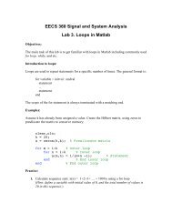
Filter Design
Filter Design
Filter Design

You also want an ePaper? Increase the reach of your titles
YUMPU automatically turns print PDFs into web optimized ePapers that Google loves.
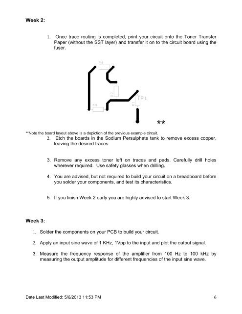
Week 2:<br />
1. Once trace routing is completed, print your circuit onto the Toner Transfer<br />
Paper (without the SST layer) and transfer it on to the circuit board using the<br />
fuser.<br />
**<br />
**Note the board layout above is a depiction of the previous example circuit.<br />
2. Etch the boards in the Sodium Persulphate tank to remove excess copper,<br />
leaving the desired traces.<br />
3. Remove any excess toner left on traces and pads. Carefully drill holes<br />
wherever required. Use safety glasses when drilling.<br />
4. You are advised, but not required to build your circuit on a breadboard before<br />
you solder your components, and test its characteristics.<br />
5. If you finish Week 2 early you are highly advised to start Week 3.<br />
Week 3:<br />
1. Solder the components on your PCB to build your circuit.<br />
2. Apply an input sine wave of 1 KHz, 1Vpp to the input and plot the output signal.<br />
3. Measure the frequency response of the amplifier from 100 Hz to 100 kHz by<br />
measuring the output amplitude for different frequencies of the input sine wave.<br />
Date Last Modified: 5/6/2013 11:53 PM 6