Filter Design
Filter Design
Filter Design

Create successful ePaper yourself
Turn your PDF publications into a flip-book with our unique Google optimized e-Paper software.
HIGH PASS<br />
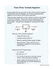
Note that the op-amp is used in its non-inverting mode (the input is connected to pin 3).<br />
The resistor-capacitor configuration between the input and the op-amp's non-inverting<br />
input provides the desired filtering.<br />
Procedure:<br />
Week 1:<br />
1. <strong>Design</strong> a <strong>Filter</strong> for the given Cut-off Frequency and Gain. The Relevant Equations<br />
for both Low pass & High pass circuits are:<br />
Gain: = 1 + R F / R G<br />
Cut off Frequency = 1 / (2 π RC)<br />
Note: Use C = 0.22uF for the capacitor in the filter network.<br />
Select R F and R G between 1 [k] and 50 [k]. If R F and R G are less than 100<br />
[] (chosen to be 1 [k] or greater for a safety margin) too much current will flow<br />
through the feedback loop, and the LM 318 will be damaged. If R F and R G are<br />
greater than 50 [k] not enough current will flow through the feedback loop, and<br />
will invalidate some of the other practical assumptions of the LM 318.<br />
Date Last Modified: 5/6/2013 11:53 PM 3