Filter Design
Filter Design
Filter Design

You also want an ePaper? Increase the reach of your titles
YUMPU automatically turns print PDFs into web optimized ePapers that Google loves.
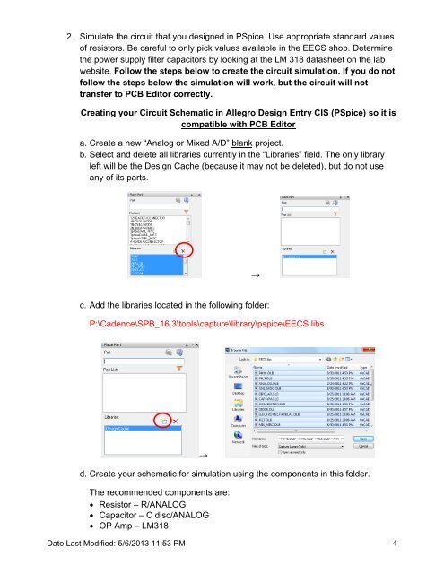
2. Simulate the circuit that you designed in PSpice. Use appropriate standard values<br />
of resistors. Be careful to only pick values available in the EECS shop. Determine<br />
the power supply filter capacitors by looking at the LM 318 datasheet on the lab<br />
website. Follow the steps below to create the circuit simulation. If you do not<br />
follow the steps below the simulation will work, but the circuit will not<br />
transfer to PCB Editor correctly.<br />
Creating your Circuit Schematic in Allegro <strong>Design</strong> Entry CIS (PSpice) so it is<br />
compatible with PCB Editor<br />
a. Create a new “Analog or Mixed A/D” blank project.<br />
b. Select and delete all libraries currently in the “Libraries” field. The only library<br />
left will be the <strong>Design</strong> Cache (because it may not be deleted), but do not use<br />
any of its parts.<br />
→<br />
c. Add the libraries located in the following folder:<br />
P:\Cadence\SPB_16.3\tools\capture\library\pspice\EECS libs<br />
→<br />
d. Create your schematic for simulation using the components in this folder.<br />
The recommended components are:<br />
Resistor – R/ANALOG<br />
Capacitor – C disc/ANALOG<br />
OP Amp – LM318<br />
Date Last Modified: 5/6/2013 11:53 PM 4