VDV MultiMedia Cable Tester - Ideal Industries Inc.
VDV MultiMedia Cable Tester - Ideal Industries Inc.
VDV MultiMedia Cable Tester - Ideal Industries Inc.

You also want an ePaper? Increase the reach of your titles
YUMPU automatically turns print PDFs into web optimized ePapers that Google loves.
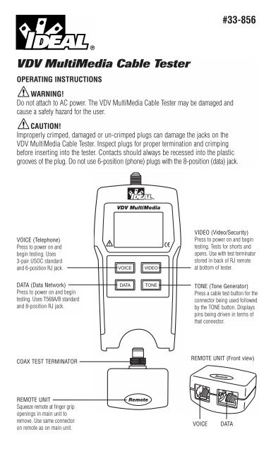
#33-856<br />
<strong>VDV</strong> <strong>MultiMedia</strong> <strong>Cable</strong> <strong>Tester</strong><br />
OPERATING INSTRUCTIONS<br />
WARNING!<br />
Do not attach to AC power. The <strong>VDV</strong> <strong>MultiMedia</strong> <strong>Cable</strong> <strong>Tester</strong> may be damaged and<br />
cause a safety hazard for the user.<br />
CAUTION!<br />
Improperly crimped, damaged or un-crimped plugs can damage the jacks on the<br />
<strong>VDV</strong> <strong>MultiMedia</strong> <strong>Cable</strong> <strong>Tester</strong>. Inspect plugs for proper termination and crimping<br />
before inserting into the tester. Contacts should always be recessed into the plastic<br />
grooves of the plug. Do not use 6-position (phone) plugs with the 8-position (data) jack.<br />
VOICE (Telephone)<br />
Press to power on and<br />
begin testing. Uses<br />
3-pair USOC standard<br />
and 6-position RJ jack.<br />
VIDEO (Video/Security)<br />
Press to power on and begin<br />
testing. Tests for shorts and<br />
opens. Use with test terminator<br />
stored in back of RJ remote<br />
at bottom of tester.<br />
DATA (Data Network)<br />
Press to power on and begin<br />
testing. Uses T568A/B standard<br />
and 8-position RJ jack.<br />
TONE (Tone Generator)<br />
Press a cable test button for the<br />
connector being used followed<br />
by the TONE button. Displays<br />
pins being driven in terms of<br />
that connector.<br />
COAX TEST TERMINATOR<br />
REMOTE UNIT (Front view)<br />
REMOTE UNIT<br />
Squeeze remote at finger grip<br />
openings in main unit to<br />
remove. Use same connector<br />
on remote as on main unit.<br />
VOICE<br />
DATA
Features:<br />
• Tests voice (6-wire), data (8-wire) and video (coax) cabling systems<br />
• Large seven-segment LCD with icons for clear results<br />
• <strong>Cable</strong> test results displayed in wire map format<br />
• Tests for shorts, opens, miswires, reversals and split pairs<br />
• Displays PASS icon for correctly wired T568A/B, both one-to-one and uplink<br />
(cross-over) cables<br />
• Displays PASS icon for correctly wired 6-pin telephone cables both<br />
straight-through and reversed<br />
• Tone generator mode for use with tone tracers<br />
• Auto-off in any mode and low power consumption for long battery life<br />
• Modular Plug Remote and Video Test Terminator store in the bottom end of the case<br />
The <strong>VDV</strong> <strong>MultiMedia</strong> <strong>Cable</strong> <strong>Tester</strong> is designed to test all common low voltage cabling<br />
systems found in today’s automated homes; voice, data or video networks. The <strong>VDV</strong><br />
<strong>MultiMedia</strong> <strong>Cable</strong> <strong>Tester</strong> has a large, bright LCD display and four momentary buttons<br />
used to directly access each function. The remote attaches to the main unit for storage<br />
and patch cable testing.<br />
The <strong>VDV</strong> <strong>MultiMedia</strong> <strong>Cable</strong> <strong>Tester</strong> is turned on by pressing any one of the four momentary<br />
function buttons and begins testing in the mode for the button pressed Telephone (VOICE),<br />
Data Network (DATA), Video/Security (VIDEO), or Tone Generator (TONE). The corresponding<br />
connectors at the top end of the tester are labeled the same as their mode switches. An<br />
LCD icon for the currently selected mode will be on or flashing on the screen. To turn the<br />
<strong>VDV</strong> <strong>MultiMedia</strong> <strong>Cable</strong> <strong>Tester</strong> off when in one of the cable test modes, press the button for<br />
a different cable test mode, but not the TONE button. Pressing the TONE button will start<br />
the tone generator in the Tel Tone, the Video Tone or Data Tone mode, depending on the<br />
current cable test mode. The tone mode will be discussed in detail later on in this section.<br />
Upon completion of a voice or data cable test, the wire map display, ID and any faults are<br />
displayed. The top line of numbers on the display represents the connector pins on the main<br />
unit. The second line of pin numbers represents the connector pin numbers of the remote,<br />
normally being the same as the top line for a one-to-one wired cable. If there is a miswire,<br />
the pin numbers on the second line will indicate the pin numbers detected and the “Fail”<br />
icon will be on. The icon and the pins involved in the error will flash. If no<br />
connection was detected for some of the pins, the first and second line of pin numbers will<br />
be blank in those pin locations. If a short is detected, the second line will have a ‘-’ in<br />
those positions along with the “Short” icon being on. If a split pair is detected, those pin<br />
positions on the first and second line will be flashing the pin numbers detected from the<br />
remote and the “Split” icon will be flashing. If there are multiple errors to display, there<br />
will be a combination of the above error displays. The ID icon will have a number directly<br />
to the right of it, indicating the remote ID number detected from the remote. A new test is<br />
in progress whenever the “Voice” or “Data” icons are on.<br />
In the video mode, the “Open”, “Short” or “Pass” icon will be on to indicate the results of<br />
a test. If the cable passes, the “ID” icon will be on as well as a remote ID number, on the<br />
bottom line of the display. The “Video” icon turns on when a test is in progress.<br />
2
As mentioned above, the tone generator operates in Voice, Data and Video modes.<br />
The different modes are provided so that the pins or pairs being driven with a tone signal<br />
are displayed in terms of one of the three connectors. The specific mode is selected by<br />
pressing one of the cable test buttons (VOICE, VIDEO or DATA) followed by the TONE<br />
button. If the <strong>VDV</strong> <strong>MultiMedia</strong> <strong>Cable</strong> <strong>Tester</strong> was off when the TONE button is pressed, the<br />
last cable test mode used will be selected. The tone generator saves the driven pins for<br />
each mode independently. For example, selecting a different pin to drive in network mode<br />
will not change the driven pin in video mode. Pressing any cable test mode button will<br />
turn off the <strong>VDV</strong> <strong>MultiMedia</strong> <strong>Cable</strong> <strong>Tester</strong> when in tone mode.<br />
1. VOICE <strong>Cable</strong> Test Mode – The <strong>VDV</strong> <strong>MultiMedia</strong> <strong>Cable</strong> <strong>Tester</strong> assumes the 6-position<br />
jack on the main unit and the remote will be used for connecting the tester to the cable<br />
run to be tested. This mode uses the 3-pair USOC standard to define the pairs. Connector<br />
pins 1-6, 2-5 and 3-4 are the pairs defined by this standard. The tester will display the<br />
“Pass” icon when all 6 pins are correctly wired in a one-to-one order. If all 6 pins are<br />
correctly wired in the reverse order, the “Pass” icon along with a flashing “Rev” icon<br />
will be displayed. Standard telephone cables used between a phone set and a wall jack<br />
are usually reverse-pinned.<br />
2. DATA <strong>Cable</strong> Test Mode – The <strong>VDV</strong> <strong>MultiMedia</strong> <strong>Cable</strong> <strong>Tester</strong> assumes the 8-position<br />
jack on the main unit and the remote will be used for connecting the tester to the cable<br />
run to be tested. The TIA/EIA568A/B standard is used to define the pairs. Connector pins<br />
1-2, 3-6, 4-5 and 7-8 are the pairs defined by this standard. The A and B standards are<br />
the same except for color-coding and are indistinguishable from each other by electrical<br />
testing. The tester will display the “Pass” icon when all 8 pins are correctly wired in a<br />
one-to-one order. If all 8 pins are correctly wired with the 1-2 and 3-6 pairs crossed,<br />
the “Pass” icon will be displayed along with a flashing “Uplink” icon. Uplink cables<br />
are also known as crossover or T568A to T568B cables and are commonly used to<br />
connect two computers or two hub/switches directly together.<br />
For shielded data cable, the remote ID will flash alternately with “S” to indicate<br />
presence of shielding.<br />
3. VIDEO COAX <strong>Cable</strong> Test Mode – The <strong>VDV</strong> <strong>MultiMedia</strong> <strong>Cable</strong> <strong>Tester</strong> can test for<br />
open, shorts and ID.<br />
4. TONE – The tone mode generates audio tones for use with tone tracers on all pairs, a<br />
selected pair or a selected pin. The signal generated on a pair has the signal on one pin<br />
and the complement of the signal on the other pin of the pair, yielding a nominal 10 volts<br />
peak-to-peak across the pair. The pin number of the pin or the letters “P” (for pin) and<br />
“S”(for shield) being driven with tone and the currently selected tone pattern are displayed<br />
on the screen along with the “Tone” icon and the icon for the connector assumed to be<br />
used. Once in the tone generator mode, the TONE button steps to the next connector<br />
pin(s) drive option for presses of less than 2 seconds. When the TONE button is pressed<br />
and held down for longer than 2 seconds, the tone pattern options are stepped through<br />
in turn until the button is released. The tone pattern options are Hi, Lo, HiLo1 and HiLo2.<br />
The HiLo options are dual or warble tones of differing pattern duration. Pressing any<br />
button other than TONE turns off the <strong>VDV</strong> <strong>MultiMedia</strong> <strong>Cable</strong> <strong>Tester</strong>. The tone will turn off<br />
automatically after about 2.4 hours.<br />
3
Volts! – The <strong>VDV</strong> <strong>MultiMedia</strong> <strong>Cable</strong> <strong>Tester</strong> monitors for voltage being present on the<br />
jacks during each test cycle. If voltage is found, the “Volts!” icon is displayed and testing<br />
stops until the voltage is removed.<br />
INSTRUCTIONS<br />
Instructions for Use <strong>VDV</strong> <strong>MultiMedia</strong> <strong>Cable</strong> <strong>Tester</strong> powers off automatically 9 minutes after<br />
the last button press in cable testing modes and after 2.4 hours in tone mode. Be sure to<br />
install a battery if using for the first time, see battery installation section.<br />
CABLE TESTING<br />
To Test Voice/Data Patch <strong>Cable</strong> (see caution about cables with bad plugs above)<br />
1. Plug one end of patch cable into main unit.<br />
2. Plug other end of cable into remote unit.<br />
3. Press VOICE or DATA as appropriate for the jack the patch cable is connected to.<br />
The <strong>VDV</strong> <strong>MultiMedia</strong> <strong>Cable</strong> <strong>Tester</strong> will turn on and begin a testing. If tester was already<br />
on, press VOICE or DATA to initiate a new test. Results are invalid if a cable is attached<br />
during a test in progress.<br />
4. To turn <strong>VDV</strong> <strong>MultiMedia</strong> <strong>Cable</strong> <strong>Tester</strong> off, press VIDEO button.<br />
To Test Video/Security Coax <strong>Cable</strong><br />
1. Attach one end of coax cable to be tested to F-connector on main unit.<br />
2. Remove remote unit from main unit by squeezing the remote lightly between the thumb<br />
and forefinger through the openings provided in the main unit and pull out of storage<br />
pocket. Remove video remote from storage pocket on backside of remote and attach to<br />
the other end of the cable to be tested.<br />
3. Press the VIDEO button to turn on the unit and begin testing. The results are updated<br />
about once a second.<br />
4. To turn <strong>VDV</strong> <strong>MultiMedia</strong> <strong>Cable</strong> <strong>Tester</strong> off, press VOICE or DATA buttons.<br />
To Place Tone on a <strong>Cable</strong><br />
1. Connect cable to be traced to a main unit jack. For best signal, do not connect a remote<br />
to the other end. Due to the shielding effect of twisted pairs, the strongest signal is<br />
obtained by having one wire of a pair carry tone. Selecting a single pin instead of a pair<br />
will do this. For video coax cable, the Tone is best applied to the shield and the shield<br />
cannot be grounded.<br />
4
2. Turn on <strong>VDV</strong> <strong>MultiMedia</strong> <strong>Cable</strong> <strong>Tester</strong> by pressing the button associated with the<br />
connector to be used followed by pressing the TONE button. Short presses of the<br />
TONE button will select a different pin. Holding down the TONE button for more than<br />
2 seconds will select a different tone pattern.<br />
3. To turn <strong>VDV</strong> <strong>MultiMedia</strong> <strong>Cable</strong> <strong>Tester</strong> off, press any button except TONE. The tone<br />
will turn off automatically after about 2.4 hours.<br />
INTERPRETING CABLE TEST RESULTS<br />
The Pass icon will be on if the cable has all pins properly connected per T568A/B for<br />
network cables or per 3-pair USOC for telephone cables. The Fail, Short, Open or Split<br />
icon will be on if there is a wiring error. The wire map will display the end-to-end<br />
connections measured whenever possible.<br />
The Pass icon will also be on with a flashing Uplink icon if a network cable has the<br />
1-2 and the 3-6 pairs transposed to indicate a properly wired uplink (crossover) cable.<br />
In Voice mode, the Rev icon will flash if all connected pins are in reverse order and the<br />
Pass icon will also be on if all 6 connections are present. Telephone modular plug cables<br />
used between the wall jack and a phone set are usually reverse pinned.<br />
Definition of Errors – The three classes of faults discussed below are in order of severity.<br />
The severity has to do with the ability of a more severe error to mask less severe errors.<br />
For example, if there is a short in the cable, miswires and split pairs may not be detected<br />
for the pairs involved in the short fault.<br />
Short – The pair has a low resistance connection from one wire of the pair to the other wire<br />
of the pair or to any other wire in the cable or the shield. A short is indicated by the Short<br />
icon being on and flashing -’s in the appropriate pin positions on the second line for the<br />
pin numbers involved in the shorts plus a flashing S icon if the shield is shorted to a pin.<br />
Miswire – A wire or both wires of a pair are not connected to the correct pins at the<br />
other end of the cable. The wire map shows the pin numbers line 1 (main) line 2 (remote).<br />
A reverse pair is a special case of a miswire in which the pair is wired to the correct pair<br />
of pins or to another designated pair of pins, but the two leads are reversed. The <strong>VDV</strong><br />
<strong>MultiMedia</strong> <strong>Cable</strong> <strong>Tester</strong> is able to test for split pair errors as long as the wiring errors<br />
are in pairs. The Fail icon and the pin numbers, which are miswired, will be flashing.<br />
Split Pair – A split pair is an error in the twisting of the wires together within the cable.<br />
The cables generally are made up of eight wires twisted together in 4 pairs. These 4 pairs<br />
are designated as pairs by the wiring standards and are intended to carry a signal and its<br />
return. 1 & 2, 3 & 6, 4 & 5 and 7& 8 are the pairs designated by T568A/B for a RJ45 jack or<br />
plug. A cable can be wired with correct continuity but not with correct pairing. This most<br />
often happens when the cable is terminated consistently at both ends, but in the wrong<br />
order. A dynamic or AC test is required to detect this type of error. If the only error is a<br />
split pair error, the cable has correct continuity. If cross talk is not a concern, as in flat<br />
satin cable, the cable is good if the only error is the split pair error. The Split icon and the<br />
pin numbers on the first and second line of the wire map with split pairs flash when there<br />
is a split pair error.<br />
5
<strong>VDV</strong> <strong>MultiMedia</strong> <strong>Cable</strong> <strong>Tester</strong> has the ability to turn off the split pair error testing. Pressing<br />
the button for the current cable test mode for more than 2 seconds turns off the split pair<br />
testing. The “Split” icon and the word “OFF” appears on the screen momentarily to indicate<br />
this. The split pair testing will resume the next time the tester is turned on, or may be toggled<br />
back on by another 2 second press of the current test mode button.<br />
BATTERY REPLACEMENT<br />
When the battery low icon is on, the battery should be replaced as soon as practical.<br />
The cable testing results will become unreliable when the battery reaches about 4.5 volts.<br />
To replace battery:<br />
1. Remove the screw from the battery door on the back of the unit with a<br />
#1 Phillips-head screwdriver.<br />
2. Pull battery out of cavity and remove battery snap.<br />
3. Connect a new Alkaline 9 volt battery to battery snaps. Place battery back into body<br />
with battery snaps placed toward front end of compartment.<br />
4. Replace battery door and screw being careful to not over tighten the screw.<br />
SPECIFICATIONS<br />
Physical Dimensions<br />
Size: 13.2 × 7.3 × 4.1 cm (5.2 × 2.9 × 1.6 inches)<br />
Weight: 242 grams (8.5 oz.) with battery and remote<br />
Environmental<br />
Operating temperature: 0 to 50 °C (32 to 122 °F)<br />
Storage temperature: -10 to 60 °C (14 to 140 °F)<br />
Humidity: 10% to 90%, non-condensing<br />
6
Battery Life<br />
(9V Alkaline battery, typical) times are for the full capacity of the battery<br />
used continuously in one of the following modes:<br />
Standby: 2.5 years<br />
<strong>Cable</strong> Testing: 150 hours<br />
Tone Generator: 250 hours<br />
<strong>Cable</strong> Types<br />
Data network cable, CAT6, CAT-5E, CAT-5, CAT-4, CAT-3 and Coax<br />
Minimum cable length for testing of split pairs<br />
1 meter (3 feet)<br />
Video Coax cable<br />
100 ohms maximum DC resistance, center conductor plus shield<br />
ACCESSORIES<br />
Satin RJ11 patchcord<br />
Satin RJ45 patchcord<br />
WARRANTY<br />
IDEAL guarantees to the end-user purchaser that its products will be free of all defects in<br />
material and/or workmanship. This warranty extends for a period of 12 months for the test<br />
instrument and 3 months for the cables from the date of manufacture or proof-of-purchase.<br />
The obligations of IDEAL under this warranty is limited to the repair or replacement (at our<br />
option) during the warranty period, of any part that proves to be defective in material or<br />
workmanship under normal use, installation and service, provided the product is returned<br />
to IDEAL freight prepaid. A copy of the purchase receipt must accompany products returned<br />
to us. In the absence of such a receipt, the warranty period will cease 12 months from the<br />
date of manufacture. This warranty does not extend to products that have been subjected<br />
to neglect, accidental or improper use, or to units which have been altered, repaired, or<br />
inspected by other than IDEAL authorized personnel. In no event will IDEAL be liable for<br />
any incidental or consequential damages. The <strong>VDV</strong> <strong>MultiMedia</strong> <strong>Cable</strong> <strong>Tester</strong> is designed<br />
and manufactured to provide trouble-free service. However, if for some reason your tester<br />
should require repair, please follow these instructions.<br />
SHIPPING<br />
1. Before returning any product to IDEAL, you must first request a Return Goods Authorization<br />
Number by contacting our Customer Services Dept. at 800-435-0705. No shipments will<br />
be accepted without this number, which must be clearly marked on the shipping label.<br />
2. Ship the equipment with a copy of the sales receipt, if available.<br />
3. Attach a description of the operational problem.<br />
4. <strong>Inc</strong>lude a contact name, phone number, and e-mail address if possible.<br />
5. Pack securely to prevent damage during shipping.<br />
6. Ship prepaid to: IDEAL INDUSTRIES, INC.; Becker Place; Sycamore, IL 60178<br />
PRODUCT REGISTRATION<br />
Please visit www.idealindustries.com
IDEAL INDUSTRIES, INC.<br />
Sycamore, IL 60178, U.S.A.<br />
800-435-0705 Customer Assistance<br />
www.idealindustries.com<br />
ND 4715-1