TMdrive-MVG Series Catalog - Tmeic.com
TMdrive-MVG Series Catalog - Tmeic.com
TMdrive-MVG Series Catalog - Tmeic.com

Create successful ePaper yourself
Turn your PDF publications into a flip-book with our unique Google optimized e-Paper software.
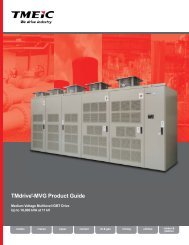
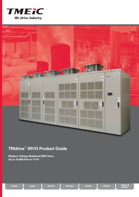
<strong>TMdrive</strong> -<strong>MVG</strong> Product Guide<br />
Medium Voltage Multilevel IGBT Drive<br />
Up to 10,000 kVA at 11 kV<br />
metals<br />
paper<br />
cement<br />
oil & gas<br />
mining<br />
utilities<br />
rubber &<br />
plastics
Global Products for Meeting Global Needs<br />
The <strong>TMdrive</strong>-<strong>MVG</strong> is a general-purpose, mediumvoltage,<br />
variable-frequency AC drive for industrial<br />
power ratings up to 10 MW, in the voltage range<br />
of 3/3.3 kV, 6/6.6 kV, and 10/11 kV. Featuring highquality<br />
Japanese design and manufacture, the<br />
<strong>TMdrive</strong>-<strong>MVG</strong> works with existing or new induction<br />
or synchronous motors and meets users' basic<br />
system requirements as described below:<br />
Design Feature<br />
Customer Benefit<br />
• Conservative design using 1700-volt IGBTs<br />
(Insulated Gate Bipolar Transistor)<br />
• High energy efficiency approx. 97%<br />
• Diode rectifier ensures power factor greater<br />
than 95% in the typical speed control range<br />
• Multiple level drive output waveform to the<br />
motor (27 levels for the 6.6 kV inverter, line to<br />
line voltage, peak to peak)<br />
• Multi-pulse converter rectifier and phase<br />
shifted transformer:<br />
3.3 kV Class: 18 pulse 10 kV Class: 54 pulse<br />
6.6 kV Class: 36 pulse 11 kV Class: 30 pulse<br />
• Designed to keep running after utility supplytransient<br />
voltage dropouts − up to 300 msec.<br />
• Synchronous transfer to line option with no<br />
interruption to motor current (Additional<br />
equipment required)<br />
• Input isolation transformer included in the<br />
drive package<br />
• Direct drive voltage output level<br />
• Highly reliable operation and expected 100,000<br />
hour (12 years) drive MTBF, based on field of<br />
experience with the large global installed base<br />
of <strong>TMdrive</strong>-MV technology<br />
• Considerable energy savings, in particular on<br />
flow control applications<br />
• Capacitors are not required for power<br />
factor correction<br />
• No derating of motor for voltage insulation<br />
or heating is required due to motor-friendly<br />
waveform<br />
• No harmonic filter required to provide<br />
lower harmonic distortion levels than<br />
IEEE-519-1992 guidelines<br />
• Uninterrupted service for critical loads<br />
• Allows control of multiple motors with<br />
one drive<br />
• No motor current or torque transients when<br />
the motor transitions to the AC line<br />
• Better protection of motor<br />
• Simplified installation<br />
• Lower cost installation<br />
• Mitigation of harmonics on the primary side<br />
• No output transformer required to match motor<br />
voltage, saving cost, mounting space, cabling,<br />
and energy<br />
• Allows easy retrofit of existing motors<br />
2
Bringing Reliable Control<br />
to a Wide Variety of Industries<br />
Cement<br />
Oil and Gas<br />
The <strong>TMdrive</strong>-<strong>MVG</strong>'s <strong>com</strong>partmentalized design streamlines<br />
installation, <strong>com</strong>missioning, and maintenance of mediumvoltage<br />
drives in the cement industry. With a Mean Time<br />
Between Failure (MTBF) exceeding 100,000 hours (12 years),<br />
the <strong>MVG</strong> is engineered to deliver rock-solid performance in<br />
virtually any application, making the <strong>TMdrive</strong>-<strong>MVG</strong> a best<br />
choice of many consultants, end users, and cement plant<br />
builders all over the world, including:<br />
• Raw mill fans, bag house fans<br />
• Preheater fans, coal mill fans<br />
• Grinding mills<br />
• Rotary kilns<br />
In the Oil and Gas Industry, the <strong>MVG</strong> family of drives can<br />
be seamlessly integrated with the rest of your pump station<br />
control system with a choice of either 3/3.3, 6/6.6, 10, or<br />
11 kV. They can be applied to existing motors and cabling,<br />
making them an excellent fit in modernization/retrofit<br />
applications, including:<br />
• Oil pumps<br />
• Gas <strong>com</strong>pressors<br />
• Fans<br />
Accurate torque control is a key in controlling large<br />
conveyors. The <strong>MVG</strong>’s flux vector algorithm provides the<br />
accuracy and response for this demanding application.<br />
Mining applications include:<br />
• Raw material conveyor<br />
• Grinding mills<br />
• Pumps<br />
Mining<br />
Utilities/Power Generation<br />
Traditional mechanical methods of controlling flow are<br />
inefficient and require considerable maintenance. In the<br />
Power Generation Utilities Industry, the <strong>MVG</strong> provides more<br />
reliable, accurate, and energy-efficient control of flow while<br />
eliminating the maintenance associated with dampers, vanes,<br />
or valves on:<br />
• Induced and forced draft fans<br />
• Primary and secondary air fans<br />
• Boiler feed water pumps<br />
• Condensate extraction pumps<br />
The metal-making part of the steel plant uses large air<br />
flows and requires high power levels supplied by the<br />
<strong>MVG</strong> to operate:<br />
• Water gas fans<br />
• BOF ID fans<br />
• Dust collection fans<br />
• Blast furnace blower fans<br />
• Utility pumps<br />
Metals<br />
3
A Look on the Inside<br />
MV Drive Technology for<br />
medium voltage operation:<br />
• <strong>Series</strong> connected inverter cell<br />
architecture uses 1700 V IGBT<br />
inverters for best reliability and high<br />
energy efficiency<br />
• Diode bridge rectifiers yield high<br />
power factor operation<br />
• Multi-winding transformer produces<br />
low input power distortion<br />
• Modular drawable power cell design<br />
minimizes the time required for any<br />
maintenance activities<br />
Input Transformer<br />
The special input<br />
transformer has phaseshifted<br />
secondary<br />
windings to produce<br />
multi-pulse converter<br />
operation. This design<br />
exceeds the IEEE 519-<br />
1992 guidelines for<br />
input current distortion.<br />
I/O Board<br />
The I/O board supports<br />
encoder, 24 V dc I/O, 115<br />
V ac inputs and analog<br />
I/O, standard. All I/O are<br />
terminated to a two-piece<br />
modular terminal block<br />
for ease of maintenance,<br />
located in right hand<br />
cabinet.<br />
Main Power Input<br />
Four voltage levels are<br />
available:<br />
• 3-3.3 kV, 3-phase,<br />
50/60 Hz<br />
• 6-6.6 kV, 3-phase,<br />
50/60 Hz<br />
• 10 kV, 3-phase,<br />
50/60 Hz<br />
• 11 kV, 3-phase,<br />
50/60 Hz<br />
Air Cooling<br />
Forced air cooling<br />
system with:<br />
• Intake through<br />
cabinet doors<br />
• Upward flow<br />
through inverter<br />
cells and transformer<br />
• Exhaust at top<br />
of cabinet<br />
Cell Inverters<br />
Example: six banks of<br />
three, series connected<br />
inverter cells, each<br />
containing:<br />
• Diode bridge rectifier<br />
• IGBT PWM inverter<br />
• DC link capacitor<br />
• Drawable module for<br />
ease of maintenance<br />
Control Functions<br />
A single set of control<br />
boards feeds all inverter<br />
cells. The primary control<br />
board performs several<br />
functions:<br />
• Speed and torque<br />
regulation<br />
• Sequencing<br />
• I/O mapping<br />
• Diagnostic data gathering<br />
• Provision for optional<br />
LAN interface<br />
4
Slide-Out Inverter Modules<br />
Each inverter cell contains a three-phase diode converter and a singlephase<br />
IGBT inverter, connected by a DC bus. One cell module is shown<br />
opposite, drawn out of the rack on a slide for service. All the modules are<br />
the same; refer to the diagram below. The mean time to repair the drive<br />
(MTTR) is 30 minutes or less.<br />
DC bus<br />
capacitor<br />
Three-phase<br />
input<br />
Single-phase<br />
output<br />
Diode bridge<br />
rectifier<br />
Inverter with<br />
1700 IGBTs<br />
Inverter Cell Module Removed from Rack<br />
Switching Devices<br />
Switching devices are Insulated Gate<br />
Bipolar Transistors (IGBT)<br />
Inverter Cell Module<br />
Cooling Heat Sink<br />
Heat is transferred from<br />
the switching device heat<br />
sink to the cooling air<br />
Input Fuse<br />
Fused three-phase inputs<br />
to converter<br />
DC Link Capacitors<br />
Smooth and maintain<br />
DC voltage supply to the<br />
inverter (on opposite side<br />
of module).<br />
Control Board<br />
• Board passes Pulse<br />
Width Modulated control<br />
signal to the gate drivers<br />
• Gate driver circuit<br />
boards connect directly<br />
to IGBTs<br />
5
<strong>TMdrive</strong>-<strong>MVG</strong> Architecture<br />
The <strong>TMdrive</strong>-<strong>MVG</strong> main circuit consists of an input transformer and single-phase PWM inverter cells.<br />
For 3 kV, three inverter cells are series connected to create an output with 7 output voltage levels.<br />
<strong>TMdrive</strong>-<strong>MVG</strong> (3 kV class)<br />
.<br />
Power<br />
supply<br />
three-phase<br />
50/60 Hz<br />
<strong>Series</strong><br />
connected<br />
inverter cells<br />
3.0–3.3 kV<br />
output<br />
Input transformer,<br />
phase shifted<br />
secondary windings<br />
for low harmonic<br />
power system impact<br />
M<br />
. .<br />
DC-bus<br />
capacitor<br />
.<br />
.<br />
Inverter Cell Module<br />
.<br />
.<br />
.<br />
.<br />
.<br />
.. .<br />
Diode<br />
rectifier<br />
Single-phase<br />
inverter<br />
6
<strong>TMdrive</strong>-<strong>MVG</strong> Specifications<br />
3.0/3.3 kV <strong>TMdrive</strong>-<strong>MVG</strong><br />
Frame<br />
Rated Output<br />
Current Amps<br />
*1<br />
3.0 kV<br />
Output<br />
kVA<br />
3.3 kV<br />
Output<br />
kVA<br />
Approx.<br />
Motor<br />
Power HP<br />
@3.3 kV *2<br />
Approx.<br />
Motor<br />
Power kW<br />
@3.3 kV *2<br />
Panel Width<br />
mm<br />
(inch)<br />
Panel<br />
Height with<br />
channel base<br />
mm<br />
(inch)<br />
Panel<br />
Depth<br />
mm<br />
(inch)<br />
Approx.<br />
Weight<br />
kg<br />
(lbs)<br />
35 180 200 200 160<br />
I<br />
53 270 300 300 225<br />
2100<br />
(83)<br />
2670<br />
(106)<br />
900<br />
(36)<br />
2700<br />
(5940)<br />
70 360 400 400 300<br />
II<br />
105 540 600 650 480<br />
140 720 800 875 650<br />
2200<br />
(87)<br />
2670<br />
(106)<br />
900<br />
(36)<br />
3400<br />
(7480)<br />
III<br />
167 860 950 1000 780<br />
193 1000 1100 1200 900<br />
228 1180 1300 1400 1000<br />
263 1360 1500 1600 1225<br />
2800<br />
(111)<br />
3100<br />
(122)<br />
2850<br />
(113)<br />
2850<br />
(113)<br />
1000<br />
(40)<br />
1100<br />
(44)<br />
4300<br />
(9460)<br />
5700<br />
(12540)<br />
315 1630 1800 1900 1400<br />
4000<br />
(158)<br />
6800<br />
(14960)<br />
IV<br />
350 1810 2000 2100 1600<br />
385 2000 2200 2400 1750<br />
4100<br />
(162)<br />
2895<br />
(114)<br />
1100<br />
(44)<br />
7400<br />
(16280)<br />
CF 665 3450 3800 4100 3100<br />
11800 2895 1100<br />
Later<br />
CF 727 3770 4150 4500 3400<br />
(465) (114) (44)<br />
Later<br />
V<br />
420 2180 2400 2600 1900<br />
525 2720 3000 3200 2400<br />
4600<br />
(182)<br />
2895<br />
(114)<br />
1300<br />
(52)<br />
9400<br />
(20680)<br />
CF 788 4090 4500 5000 3700<br />
12800 2895 1300<br />
Later<br />
CF 998 5180 5700 6200 4600<br />
(504) (114) (52)<br />
Later<br />
Notes:<br />
For cabinet clearances, overload ratings, and power calculations, see page 11<br />
*1 1.25 PU overload, 60 sec rating; use Frame Amp rating for most acceptable match with motor<br />
*2 Approximate capacity for 3.3 kV-based 6-pole induction motors with typical efficiency (0.94) and power factor (0.87)<br />
CF These are two banks; consult factory for dimensions and weights<br />
Redundant cooling fans increase height<br />
7
<strong>TMdrive</strong>-<strong>MVG</strong> Specifications<br />
6.0/6.6 kV <strong>TMdrive</strong>-<strong>MVG</strong><br />
Frame<br />
Rated Output<br />
Current Amps<br />
*3<br />
6.0 kV<br />
Output<br />
kVA<br />
6.6 kV<br />
Output<br />
kVA<br />
Approx.<br />
Motor<br />
Power HP<br />
@6.6 kV *4<br />
Approx.<br />
Motor<br />
Power kW<br />
@6.6 kV *4<br />
Panel Width<br />
mm<br />
(inch)<br />
Panel<br />
Height with<br />
channel base<br />
mm<br />
(inch)<br />
Panel<br />
Depth<br />
mm<br />
(inch)<br />
Approx.<br />
Weight<br />
kg<br />
(lbs)<br />
35 360 400 400 300<br />
I<br />
53 540 600 650 475<br />
3200<br />
(126)<br />
2670<br />
(106)<br />
900<br />
(36)<br />
3800<br />
(8360)<br />
70 720 800 875 650<br />
II<br />
105 1090 1200 1300 950<br />
140 1450 1600 1750 1300<br />
4000<br />
(158)<br />
2700<br />
(107)<br />
900<br />
(36)<br />
1000<br />
(40)<br />
5400<br />
(11880)<br />
7000<br />
(15400)<br />
III<br />
167 1720 1900 2000 1500<br />
193 2000 2200 2400 1800<br />
228 2360 2600 2800 2000<br />
263 2720 3000 3200 2400<br />
5000<br />
(197)<br />
5100<br />
(201)<br />
2750<br />
(109)<br />
1000<br />
(40)<br />
1100<br />
(44)<br />
7800<br />
(17160)<br />
9100<br />
(20020)<br />
315 3270 3600 3900 2900<br />
350 3630 4000 4300 3200<br />
6100<br />
(241)<br />
12000<br />
(26400)<br />
IV<br />
385 4000 4400 4800 3500<br />
CF 595 6180 6800 7500 5500<br />
2895<br />
(114)<br />
1200<br />
(48)<br />
Later<br />
CF 665 6900 7600 8300 6000<br />
15800<br />
(622)<br />
Later<br />
CF 731 7590 8350 9000 6800 Later<br />
420 4360 4800 5000 3900<br />
473 4900 5400 6000 4400<br />
6300<br />
(248)<br />
15200<br />
(33440)<br />
V<br />
525 5450 6000 6500 4900<br />
CF 797 8270 9100 10000 7400<br />
16200<br />
(638)<br />
2895<br />
(114)<br />
1400<br />
(56)<br />
Later<br />
CF 898 9320 10260 11000 8350<br />
16600<br />
(654)<br />
Later<br />
CF 998 10360 11400 12000 9300<br />
16800<br />
(662)<br />
Later<br />
Notes:<br />
*3 1.25 PU overload, 60 sec rating; use Frame Amp rating for most acceptable match with motor<br />
*4 Approximate capacity for 6.6 kV-based 6-pole induction motors with typical efficiency (0.94) and power factor (0.87)<br />
CF These are two banks; consult factory for dimensions and weights<br />
Redundant cooling fans increase height<br />
8
10/11 kV <strong>TMdrive</strong>-<strong>MVG</strong><br />
Frame<br />
Rated Output<br />
Current Amps<br />
*5<br />
10 kV<br />
Output<br />
kVA<br />
11 kV<br />
Output<br />
kVA<br />
Approx.<br />
Motor<br />
Power HP<br />
@11 kV *6<br />
Approx.<br />
Motor<br />
Power kW<br />
@11 kV *6<br />
Panel Width<br />
mm<br />
(inch)<br />
Panel<br />
Height with<br />
channel base<br />
mm<br />
(inch)<br />
Panel<br />
Depth<br />
mm<br />
(inch)<br />
Approx.<br />
Weight<br />
kg<br />
(lbs)<br />
35 600 660 700 500<br />
I<br />
53 900 990 1100 800<br />
5600<br />
(221)<br />
3250<br />
(128)<br />
1400<br />
(56)<br />
8750<br />
(19260)<br />
70 1200 1320 1400 1000<br />
87 1500 1650 1800 1350<br />
II<br />
105 1800 2000 2200 1600<br />
122 2100 2300 2500 1800<br />
6800<br />
(268)<br />
3250<br />
(128)<br />
1400<br />
(56)<br />
10850<br />
(23880)<br />
140 2400 2640 2900 2100<br />
III<br />
162 2800 3080 3500 2500<br />
191 3300 3630 4000 3000<br />
226 3900 4290 4500 3500<br />
263 4500 5000 5500 4000<br />
7500<br />
(296)<br />
7700<br />
(304)<br />
3250<br />
(128)<br />
1500<br />
(60)<br />
15500<br />
(34110)<br />
18500<br />
(40700)<br />
315 5400 6000 6500 4900<br />
IV<br />
347 6000 6600 7200 5400<br />
12800<br />
(504)<br />
3250<br />
(128)<br />
1500<br />
(60)<br />
29350<br />
(64580)<br />
386 6680 7350 7800 5800<br />
420 7200 8000 8700 6500<br />
V<br />
473 8100 9000 9800 7300<br />
12800<br />
(504)<br />
3250<br />
(128)<br />
1500<br />
(60)<br />
29850<br />
(65680)<br />
525 9000 10000 10900 8000<br />
Notes:<br />
*5 1.25 PU overload, 60 sec rating; use Frame Amp rating for most acceptable match with motor<br />
*6 Approximate capacity for 11 kV-based 6-pole induction motors with typical efficiency (0.94) and power factor (0.87)<br />
Redundant cooling fans increase height<br />
9
<strong>TMdrive</strong>-<strong>MVG</strong> Specifications<br />
Cabinet Minimum Maintenance Space<br />
Drive Frame Capacity<br />
Front Side<br />
Space<br />
Rear Side<br />
Space<br />
Ceiling<br />
Height<br />
Minimum Height<br />
of Ceiling for<br />
Maintenance<br />
3/3.3<br />
kV<br />
class<br />
I 400 kVA 1600 mm (63 in) 20 mm (0.8 in)<br />
II 800 kVA 1600 mm (63 in) 20 mm (0.8 in)<br />
III 1500 kVA 1700 mm (67 in) 20 mm (0.8 in)<br />
IV 2200 kVA 1700 mm (67 in) 20 mm (0.8 in)<br />
3050<br />
3100<br />
Front side<br />
maintenance<br />
space<br />
Rear side<br />
maintenance<br />
space<br />
V 3000 kVA 1900 mm (75 in) 20 mm (0.8 in)<br />
6/6.6<br />
kV<br />
class<br />
I 800 kVA 1600 mm (63 in) 20 mm (0.8 in)<br />
II 1600 kVA 1600 mm (63 in) 20 mm (0.8 in)<br />
III 3000 kVA 1700 mm (67 in) 20 mm (0.8 in)<br />
IV 4400 kVA 1700 mm (67 in) 20 mm (0.8 in)<br />
3050<br />
3100<br />
V 6000 kVA 1900 mm (75 in) 20 mm (0.8 in)<br />
10/11<br />
kV<br />
class<br />
I 1320 kVA 1800 mm (71 in) 600 mm (24 in)<br />
II 2640 kVA 1800 mm (71 in) 600 mm (24 in)<br />
III 5000 kVA 1900 mm (75 in) 600 mm (24 in)<br />
IV 7350 kVA 2000 mm (79 in) 600 mm (24 in)<br />
3500<br />
3550<br />
V 10000 kVA 2000 mm (79 in) 600 mm (24 in)<br />
Notes<br />
1. kVA Inverter = (Power Mtr Shaft ) / (Mtr PF x Mtr Eff)<br />
I Phase = (kVA Inverter ) x (1000) / (1.732) x<br />
(V Mtr Line to Line )<br />
• Mtr PF – 0.87, Mtr Eff = 0.94, ambient temperature is<br />
32˚F–104˚F (0˚C–40˚C).<br />
• Ratings based on a variable torque load (industrial<br />
fans and pumps).<br />
• Altitude above sea level is 0–3300 ft (0–1000 m).<br />
• Dimensions to top of cooling fans are for the<br />
nonredundant type fans.<br />
2. An optional bypass circuit can be separately mounted.<br />
3. Redundant cooling fans are available as an option;<br />
overall height increases.<br />
4. No rear access is required except for 10/11 kV<br />
Class drives.<br />
5. In<strong>com</strong>ing power cabling and motor cabling are bottom<br />
entry; top entry is an option.<br />
6. Air is pulled in through the filters in the cabinet doors<br />
and vented out the top.<br />
7. Available options include motor cooling fans and<br />
control, cabinet space heater, bypass power/control<br />
and dv/dt filter, HV input, sync motor control, smooth<br />
transfer to and from utility.<br />
8. For conservative sizing of cooling equipment,<br />
heat rejection is 3 kW/100 kVA (3 kW/100 hp) of output<br />
power.<br />
9. The panels are fixed to the channel bases and shipped.<br />
10
Features of the <strong>TMdrive</strong>-<strong>MVG</strong><br />
A Clean Wave Inverter<br />
Using the multiple winding input transformer,<br />
the <strong>TMdrive</strong>-<strong>MVG</strong> has multi-pulse rectification<br />
and more than meets the requirements of<br />
IEEE-519 (1992). This reduces the harmonic<br />
current distortion on the power source and<br />
protects the other equipment in the plant.<br />
The harmonic current content measured in an<br />
actual load test is <strong>com</strong>pared with IEEE-519 in<br />
the chart opposite.<br />
Input Voltage<br />
Input Current<br />
Typical Input Wave Forms<br />
Typical Harmonic Contents<br />
of Input Current for 18-pulse System<br />
A Clean Output Wave<br />
As a result of the multilevel PWM control,<br />
the output waveform is close to a sine wave,<br />
and the heat loss caused by harmonics is<br />
negligible. In addition, harmonic currents in<br />
the motor are minimized so there is very little<br />
torque ripple on the output shaft.<br />
Current and Voltage Output<br />
Waveforms for 3 kV Drive<br />
Current and Voltage Output<br />
Waveforms for 6 kV Drive<br />
A Higher Efficiency than<br />
Conventional Drives<br />
Actual factory load tests show the<br />
drive efficiency is approximately 97%<br />
(design value). This high efficiency is<br />
a result of:<br />
• A smaller number of switching<br />
semiconductors by using<br />
1700 V IGBTs<br />
• Lower switching frequencies using<br />
multilevel PWM control reduce the<br />
switching loss of each IGBT<br />
• Direct connection of MV motor<br />
without an output transformer<br />
Example: 6.6 kV drive at 6,000 kVA and 50 Hz<br />
Current 100% 75% 50%<br />
Efficiency 97.1% 97.2% 97.5%<br />
Except for the consumption of control power and auxiliary power.<br />
A High Input Power Factor<br />
Each inverter cell has a diode bridge<br />
rectifier. As a result, the input power<br />
factor is above 95% over the entire<br />
normal operating speed range,<br />
even when driving a multiple-pole<br />
induction motor of low power factor.<br />
With this high power factor, no<br />
power factor correction capacitor is<br />
required.<br />
Power Factor in Italic,<br />
Expressed in %<br />
Percent of Top Speed vs % PF Lagging<br />
* = Interpolated<br />
Value<br />
20 40 60 80 100<br />
20 94.7% 95.5% *95.6% *95.7% 95.8%<br />
Percent of<br />
Full Load<br />
40 96.6% 96.7% *96.4% 96.2%<br />
60 96.3% 96.4% 96.4%<br />
80 96.1% 96.8%<br />
100 97.1%<br />
Examples of measured power factor<br />
11
Common Control Boards to<br />
Reduce Cost of Ownership<br />
Standard Connections<br />
Main Power Supply<br />
Control power for cooling<br />
fan 380/400/415/440 V<br />
3-phase – 50/60 Hz<br />
Control power supply<br />
200 Vac-3 Ph - 50 Hz<br />
220 Vac-3 Ph - 60 Hz<br />
Option: 380/400/415/440 V<br />
– 50/60 Hz<br />
Start/stop sign<br />
Emergency<br />
stop signal<br />
Control I/O<br />
Control Area<br />
Analog Inputs<br />
Analog Outputs<br />
Digital Inputs<br />
Digital Outputs<br />
Speed Feedback<br />
Encoder Input<br />
Reference signals<br />
+/- 0–10 V<br />
or 4–20 mA<br />
LAN Interface Options<br />
Motor Temperature<br />
Sensor<br />
RUN<br />
EM<br />
Display and Diagnostics<br />
PC Configuration<br />
Keypad and Display<br />
Instrumentation Interface<br />
<strong>TMdrive</strong>-<strong>MVG</strong><br />
Output frequency<br />
4-20 mA<br />
Output speed<br />
4-20 mA<br />
BLR<br />
FAULT<br />
RUN<br />
READY<br />
3–11kV output<br />
M<br />
In<strong>com</strong>ing<br />
CB “close”<br />
To trip circuit<br />
of in<strong>com</strong>ing<br />
CB<br />
Specifications<br />
(2) ± 10 V or 4–20 mA, configurable, differential<br />
(4) ± 10 V, 8-bit, configurable, 10 mA max<br />
(2) 24–110 V dc or 48–120 V ac; (6) 24 V dc, configurable<br />
(6) 24 V dc open collector 50 mA<br />
High-resolution tach, 10 kHz, 5 or 15 V dc diff. input,<br />
A Quad B, with marker<br />
Profibus-DP, ISBus, DeviceNet , TOSLINE -S20, or<br />
Modbus RTU<br />
High-resolution torque motor temperature feedback:<br />
1 K Ohm platinum resistor or 100 Ohm platinum RTD<br />
(uses analog input with signal conditioner)<br />
Specifications<br />
Control System Drive Navigator for configuration, local<br />
and remote monitoring, animated block diagrams,<br />
dynamic live and capture buffer based trending, fault<br />
diagnostics, <strong>com</strong>missioning wizard, and regulator<br />
tune-up wizards. Ethernet 10 Mbps point to point or<br />
multi-drop, each drive has its own IP address<br />
Backlit LCD, animated displays<br />
• Parameter editing<br />
• Four configurable bar graphs<br />
• Drive control<br />
Two analog outputs dedicated to motor current<br />
feedback, plus five analog outputs that can be<br />
mapped to variables for external data logging<br />
and analysis<br />
Additional Specifications<br />
Power System Input and Harmonic Data<br />
• Voltage: up to 11 kV, 3-phase, +10%/–10%<br />
• Tolerates power dips up to 25% without tripping,<br />
<strong>com</strong>plete power loss ride through of 300 msec<br />
• 125% Overload (OL) for 60 seconds; other OL ratings available<br />
• Frequency: 50 Hz or 60 Hz, ±5%<br />
• Power factor (PF): 0.95 lag<br />
• True PF: greater than 0.95 lag over 40–100% speed range<br />
• Exceeds the IEEE 519-1992 standard for harmonics,<br />
without filters<br />
• Bottom cable entry<br />
Converter Type<br />
• AC-fed multi-pulse diode using phase shifted transformer<br />
Transformer<br />
• Dry type transformer<br />
• Air cooled type<br />
• Multi LV windings<br />
Inverter<br />
• Multilevel inverter cells:<br />
three in series for 3.3 kV inverter<br />
six in series for 6.6 kV inverter<br />
nine in series for 10 kV inverter<br />
ten in series for 11 kV inverter<br />
• 0–72 Hz<br />
• Up to 120 Hz, option for 3/3.3 and 6/6.6 kV<br />
• For 10/11 kV, maximum frequency 72 Hz<br />
• Multilevel output for motor-friendly waveform<br />
Applicable Standards<br />
• IEC61800-4, JIS, JEC, JEM<br />
Control<br />
• Nonvolatile memory for parameters and fault data<br />
• Vector control with or without speed feedback, or Volts/Hz<br />
• Designed to keep running after utility supply transient voltage<br />
dropouts of 300 ms<br />
• Synchronous transfer to line option<br />
• Synchronous motor control (option)<br />
Vector Control Accuracy and Response<br />
• Maximum speed regulator response: 20 rad/sec<br />
• Speed regulation without speed sensor ± 0.5%<br />
• Maximum torque current response: 500 rad/sec<br />
• Torque accuracy: ± 3% with temp sensor, ± 10% without<br />
Major Protective Functions<br />
• Inverter overcurrent, overvoltage<br />
• Low or loss of system voltage<br />
• Motor ground fault<br />
• Motor overload<br />
• Cooling fan abnormal<br />
• Over-temperature<br />
• CPU error<br />
Mechanical Specifications<br />
Operating Environment and Needs<br />
• Temperature: 0˚ to +40˚C<br />
• Humidity: 85% maximum, noncondensing<br />
• Altitude: Up to 1000 m (3300 ft) above sea level:<br />
• Fan: 380/400/440 Vac, 3 phase, 50 Hz or 60 Hz<br />
Cooling<br />
• Air-cooled with fans on top<br />
Sound<br />
• Approx. 76-79 dB(A)@50Hz, at 3.1ft (1 m) from enclosure<br />
• Approx. 80-83 dB(A)@60Hz, at 3.1ft (1 m) from enclosure<br />
Enclosure<br />
• IP30 except for fan openings (IEC 60529), NEMAI<br />
gasketted equivalent<br />
• Color: Munsell 5Y7/1 (Option: ANSI 61 gray, RAL7032 etc.)<br />
12
Drive/Motor Monitoring<br />
Operator Keypad<br />
High Function Display<br />
• LCD backlight gives<br />
great visibility and<br />
long life<br />
• Bar graphs, icons,<br />
menus, and digital<br />
values <strong>com</strong>bine to<br />
provide concise<br />
status information,<br />
often eliminating the<br />
need for traditional<br />
analog meters<br />
Easy-to-understand<br />
navigation buttons<br />
allow quick access to<br />
information without<br />
resorting to a<br />
PC-based tool<br />
Switch to local<br />
mode to operate<br />
the equipment from<br />
the keypad<br />
RJ-45 Ethernet port<br />
is used for the local<br />
Drive Navigator<br />
(toolbox) connection<br />
Instrumentation Interface<br />
• Two analog outputs are dedicated to motor current feedback<br />
• Five analog outputs are mapped to variables for external<br />
data logging and analysis<br />
Interlock button<br />
disables the drive<br />
Display<br />
Group<br />
Icon<br />
Status Indication<br />
Multi-language Keypad – Optional Operator Interface (below)<br />
Heartbeat<br />
Communication OK<br />
Communication error<br />
Control<br />
State<br />
Local mode<br />
Remote mode<br />
Test mode<br />
Fault<br />
State<br />
Blank<br />
Drive OK<br />
Alarm state<br />
Trip fault<br />
Blinking<br />
Drive<br />
Indication<br />
Motion<br />
Forward rotation<br />
Reverse rotation<br />
Drive not ready<br />
Drive not running<br />
Drive running forward<br />
Drive running reverse<br />
The optional multi-language keypad is a touch-panel display with<br />
the same functionality as the standard keypad. Chinese version is<br />
shown here. The main features are:<br />
• 5.7 inch (145 mm) LCD color display<br />
• Choice of languages, touch selection:<br />
-English<br />
-Japanese<br />
-Chinese<br />
-Russian<br />
-Spanish<br />
-French<br />
-Portuguese<br />
-Italian<br />
-Korean<br />
• The Ethernet <strong>com</strong>munication with the drive, analog check pins,<br />
interlock button, and status LEDs are mounted separately<br />
13
Drive Navigator — Configuration, Monitoring & Analysis<br />
Drive Configuration<br />
All the <strong>TMdrive</strong> family of drives<br />
are configured and <strong>com</strong>missioned<br />
with the Windows-based Drive<br />
Navigator. Wizards intelligently<br />
guide the user through the<br />
required steps. Included are live<br />
block diagrams, highly integrated<br />
help, and high-performance<br />
diagnostics. Several sets of drives<br />
can be maintained using Ethernet<br />
<strong>com</strong>munication. The control block<br />
display opposite shows the main<br />
drive control functions together<br />
with real-time values of the<br />
important variables. Available<br />
Navigator functions include:<br />
Parameter (Set Point) Control<br />
• Loading and saving a<br />
parameter file<br />
• Changing a parameter<br />
• Comparing parameter files<br />
Real-Time Drive Block Diagram<br />
Support Functions<br />
• Control block display<br />
• Snapshot function<br />
• Step response test<br />
• Response wave display<br />
Drive Troubleshooting<br />
This screen displays a<br />
drive first fault and shows<br />
selected trend displays to<br />
assist in determining the<br />
cause. The fastest trend<br />
displays four variables<br />
sampled at a rate of 333<br />
microseconds. The other<br />
two slower trends are<br />
sampled at 1 millisecond<br />
and 100 milliseconds.<br />
Available<br />
Troubleshooting<br />
Functions:<br />
• First fault display<br />
• Operation<br />
preparation display<br />
• Fault trace back<br />
• Trouble records<br />
• Fault history display<br />
• Online manual<br />
14<br />
100 msec.<br />
sampling<br />
1 msec.<br />
sampling<br />
333 micro sec.<br />
sampling
Energy Savings Payback Calculations<br />
Appendix. Energy Savings Payback Calculations<br />
Replacing a mechanical speed control device with an adjustable speed drive usually produces large energy savings plus a<br />
reduction in maintenance costs. This appendix outlines how the energy savings can be calculated as follows:<br />
1. Calculate the cost of energy used by the electric drive speed control system, outlined on this page.<br />
2. Calculate the cost of energy used by the mechanical speed control system, outlined on the next page.<br />
The difference is the energy cost savings. Typical power consumption curves for pumps and fans are shown below.<br />
Power (pu)<br />
1.0<br />
0.8<br />
o<br />
0.6<br />
0.4<br />
0.2<br />
0<br />
Pump with<br />
throttling valve<br />
Energy<br />
savings<br />
o<br />
o<br />
o<br />
o<br />
20% 40% 60% 80% 100%<br />
o<br />
Electrical<br />
ASD<br />
RPM/Flow (pu)<br />
Example: Pump power savings using electric drive (ASD)<br />
Power (pu)<br />
1.0<br />
0.8<br />
0.6<br />
0.4<br />
0.2<br />
0<br />
Fan with<br />
damper<br />
Energy<br />
savings<br />
Fan with inlet<br />
guide vanes<br />
Electrical<br />
ASD<br />
0% 20% 40% 60% 80% 100%<br />
RPM / Flow (pu)<br />
Example: Fan power savings using electric drive (ASD)<br />
Below is an example of the energy cost calculation for a pump driven by a motor and electric drive. The calculation for the<br />
mechanical system is similar and is described on the next page. Since energy consumption varies with speed and flow, you<br />
need the load profile table which shows the number of hours running at the various flows. Refer to the example below.<br />
Energy Cost for Electric Drive Speed Control<br />
Step 9<br />
Step 8<br />
Step 6<br />
Energy Cost<br />
Input kW<br />
$0.07/kWh<br />
1,212<br />
Energy<br />
Drive<br />
Cost<br />
Efficiency<br />
$371,500/yr<br />
96.5%<br />
Step 10<br />
Step 7<br />
Calculation<br />
details<br />
Three-Phase<br />
Electric Supply<br />
Electric<br />
Adjustable<br />
Speed<br />
Drive<br />
Motor<br />
Step 4<br />
Motor<br />
Input kW<br />
Shaft kW<br />
1,169<br />
Motor<br />
1,119<br />
Input<br />
Efficiency<br />
Shaft hp<br />
95.7%<br />
1,500<br />
Step 5<br />
Step 3<br />
Electric Motor<br />
Shaft<br />
Variable speed motor<br />
Pump<br />
Chart & Load<br />
Curve<br />
Step 2<br />
Variable speed pump<br />
Step1<br />
Desired<br />
Flow<br />
90%<br />
Start<br />
here<br />
Output Flow<br />
and Pressure<br />
Step 1<br />
Step 2<br />
Step 3<br />
Select the desired pump<br />
output flow, for example<br />
90%, and number of<br />
hours/day at this flow,<br />
for example 12.<br />
Obtain the variable<br />
speed pump<br />
performance chart and<br />
the load pressure-flow<br />
curve, which is the flow<br />
resistance of the<br />
process being fed.<br />
Find the pump input<br />
power.<br />
Percent Pressure (or Head)<br />
100<br />
Pump Performance Chart & Load Curve<br />
Load Curve<br />
(Process)<br />
Pump Chart<br />
Speed N2<br />
1,800 rpm<br />
80<br />
B<br />
1,500 hp<br />
A<br />
90 100<br />
Percent Output Flow<br />
Pump hp<br />
2,000<br />
Overlay the load pressure-flow curve on the pump<br />
chart and find the pump input shaft horsepower at<br />
the 90% flow (point B). You need the load profile.<br />
See example below.<br />
Pump input power at N2 rpm = 1,500 hp<br />
at point B, 90% flow.<br />
Daily Load Profile (example)<br />
Operation<br />
Hours/day<br />
Percent<br />
Flow<br />
5<br />
100%<br />
12<br />
90%<br />
5<br />
80%<br />
1<br />
70%<br />
1<br />
60%<br />
Step 4<br />
Convert the input shaft<br />
horsepower to shaft kW<br />
Conversion: Horsepower x 0.746 = kW<br />
Input shaft kW = 1,500 hp x 0.746 = 1,119 kW<br />
Step 5<br />
Step 6<br />
Obtain the electric<br />
motor efficiency<br />
Example: Induction motor efficiency 95.7% from<br />
manufacturer's data sheets (find at each RPM)<br />
Motor input power = 1,119 kW/0.957 Efficiency<br />
= 1,169 kW<br />
Step 7<br />
Step 8<br />
Obtain the adjustable<br />
speed drive efficiency<br />
Example: Drive efficiency 96.5% from manufacturer's<br />
data sheets (find at each RPM)<br />
Drive input power = 1,169 kW/0.965 Efficiency<br />
= 1,212 kW<br />
Step 9<br />
Step 10<br />
Obtain the electric<br />
power cost<br />
Example: Energy cost = $0.07/kWh. Calculate cost for<br />
the hours at this flow from load profile; in this example it<br />
is 12 hours/day.<br />
Energy cost = 1,212 kW x 0.07$kWh x 12 hrs/day<br />
x 365 days per year = $371,500 per year. (Repeat<br />
calculation for other flows in load profile and total).<br />
15
TMEIC Drives Offer Complete Coverage<br />
<strong>TMdrive</strong>-<strong>MVG</strong><br />
Volts<br />
TM-XL85<br />
11,000<br />
10,000<br />
<strong>TMdrive</strong>-<strong>MVG</strong><br />
<strong>TMdrive</strong>-<strong>MVG</strong><br />
7,200<br />
<strong>TMdrive</strong>-XL 85<br />
<strong>TMdrive</strong>-XL55<br />
6,600<br />
<strong>TMdrive</strong>-<strong>MVG</strong><br />
<strong>TMdrive</strong>-XL 55<br />
<strong>TMdrive</strong>-XL 75<br />
3,800<br />
<strong>TMdrive</strong>-XL 80<br />
<strong>TMdrive</strong>-70<br />
3,300<br />
1,250<br />
<strong>TMdrive</strong>-<strong>MVG</strong><br />
<strong>TMdrive</strong>-30<br />
<strong>TMdrive</strong>-50<br />
<strong>TMdrive</strong>-80<br />
<strong>TMdrive</strong>-70<br />
4<br />
5.4<br />
100<br />
1,000<br />
10,000<br />
134 1,340<br />
13,400<br />
20,000<br />
26,800<br />
50,000<br />
67,000<br />
100,000 kW<br />
134,000 Hp<br />
Global Office Locations:<br />
Toshiba Mitsubishi-Electric Industrial<br />
Systems Corporation<br />
Mita 43 MT Bldg.<br />
13-16 Mita 3 chome, Minato-ku Tokyo<br />
108-0073 Japan<br />
Tel.: +81-3-5441-9788<br />
Fax: +81-3-5441-9795<br />
Web: www.tmeic.co.jp/global/index.html<br />
TMEIC Corporation (USA)<br />
Office: 1325 Electric Road, Suite 200<br />
Roanoke, VA, United States 24018<br />
Mailing: 2060 Cook Drive<br />
Salem, VA, United States 24153<br />
Tel.: +1-540-283-2000<br />
Fax: +1-540-283-2001<br />
Web: www.tmeic.<strong>com</strong><br />
TMEIC Industrial Systems India Pvt Limited<br />
Tel.:+91 40 4434 0000<br />
Shanghai TMEIC Electric Drive Technology Co.<br />
Rm 2901, Shanghaimart, 2299 Yan'An Rd. (W),<br />
Changning District, Shangai 200336, P.R. China<br />
Tel.: +86 21 62360588 ex 717<br />
Fax: +86 21 64413019<br />
TMEIC Asia Company Limited<br />
150 Beach Road #15-08 Gateway West, Singapore 189720<br />
Tel.: +65 6292 7226<br />
Fax: +65 6292 0817<br />
Toshiba Mitsubishi-Electric Industrial<br />
Systems (Beijing) Corp.<br />
21/F., Building B, In.do Mansion<br />
48 Zhichunlu A, Haidian District,<br />
Beijing 100098, PRC<br />
Tel.: +86 10 5873-2277<br />
Fax: +86 10 5873-2208<br />
Email: sales@tmeic-cn.<strong>com</strong><br />
TMEIC Europe Limited<br />
6-9 The Square, Stockley Park,<br />
Uxbridge, Middlesex, United Kingdom,<br />
UB11 1FW<br />
Tel.: +44 870 950 7220<br />
Fax: +44 870 950 7221<br />
Email: info@tmeic.eu<br />
Web: www.tmeic.<strong>com</strong><br />
Germany Office<br />
Tel.: +49 699 819 4722<br />
Italy Office<br />
Tel.: +39 080 5046190<br />
<strong>TMdrive</strong> is a trademark of Toshiba Mitsubishi-Electric Industrial Systems Corporation.<br />
All other products mentioned are registered trademarks and/or trademarks of their<br />
respective <strong>com</strong>panies.<br />
All specifications in this document are subject to change without notice. The above<br />
brochure is provided free of charge and without obligation to the reader or to<br />
TMEIC, and is for informational purposes only. TMEIC does not accept, nor imply,<br />
the acceptance of any liability with regard to the use of the information provided.<br />
TMEIC provides the information included herein as is and without warranty of any<br />
kind, express or implied, including but not limited to any implied statutory warranty<br />
of merchantability or fitness for particular purposes. The brochure is not an implied<br />
or express contract.<br />
© 2009 Toshiba Mitsubishi-Electric Industrial Systems Corporation, Japan<br />
All Rights Reserved<br />
A-0024-1110-E