Variable Frequency Drives - a Comparison of VSI ... - Tmeic.com
Variable Frequency Drives - a Comparison of VSI ... - Tmeic.com
Variable Frequency Drives - a Comparison of VSI ... - Tmeic.com

Create successful ePaper yourself
Turn your PDF publications into a flip-book with our unique Google optimized e-Paper software.
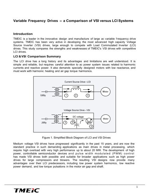
<strong>Variable</strong> <strong>Frequency</strong> <strong>Drives</strong> - a <strong>Comparison</strong> <strong>of</strong> <strong>VSI</strong> versus LCI SystemsIntroductionTMEIC is a leader in the innovative design and manufacture <strong>of</strong> large ac variable f requency drivesystems. TMEIC has been very active in developing the most advanced high capacity VoltageSource Inverter (<strong>VSI</strong>) drives, large enough to <strong>com</strong>pete with Load Commutated Inverter (LCI)drives. This study <strong>com</strong>pares the strengths and weaknesses <strong>of</strong> TMEIC's <strong>VSI</strong> drives with <strong>com</strong>petitiveLCI drives.LCI & <strong>VSI</strong> <strong>Comparison</strong> SummaryThe LCI drive has a long history and its advantages and limitations are well understood. It issimple and reliable, but requires careful attention to ac power system issues related to harmoniccurrents and reactive power. It also demands specially designed motors with low reactance, andmust work with harmonic heating and air gap torque harmonics.Figure 1. Simplified Block Diagram <strong>of</strong> LCI and <strong>VSI</strong> <strong>Drives</strong>Medium voltage <strong>VSI</strong> drives have progressed significantly in the past 15 years, and are now thestandard practice in such demanding applications as main drives in metal processing, whichrequire high overload with very high performance up to about 20 MW. The development <strong>of</strong> highpower, controllable semiconductor devices and pulse width modulated (PWM) controlhas made <strong>VSI</strong> drives both possible and suitable for broader applications such as high powerdrives for large <strong>com</strong>pressors and blowers. The resulting <strong>VSI</strong> designs now provide manyadvantages over their LCI predecessors, including low power system harmonics, low reactivepower demand, and low torque pulsations in the motor air gap and shaft.________________________________________________________________________________________________________1
1. Summary <strong>Comparison</strong> <strong>of</strong> <strong>VSI</strong> versus LCI Technology & SystemsThe following table summarizes the differences between <strong>VSI</strong> drives and LCI drives. These will bediscussed in later sections.Line Current TotalHarmonicDistortionAir gap torquerippleInput PowerFactorPower systemstabilityAC powerdisturbanceReliability, MTBFRepair time,MTTREquipment sizeMotorMotor typesMotor power andDriveDrive outputvoltage<strong>VSI</strong> System2 % THDHarmonic filter is notrequired0.5 – 1 %Standard mechanicalsystem design is possibleGreater than 0.95PF correction equipment isnot necessaryStableRide through or Automaticrestart28 yearsProven technologyAbout 0.5 hoursStandard <strong>VSI</strong> drive lineupIndependent fromconverterInduction or Synchronousmotor100 MW, 4 banksTMdrive-XL85XL type <strong>VSI</strong> up to 7.2 kV;MVG type <strong>VSI</strong> up to 11 kVLCI SystemUp to 12 % THDHarmonic filter is requiredUp to 7 %Special mechanical system designrequired for torque pulsations0.5 – 0.92Power factor equipment (capacitor)is necessaryDelicateCan ride throughGreater than 10 year MTBFProven technologyAbout 2 hoursMuch more space required for LCIlineup, Harmonic Filter, PFcorrection, and ReactorSpecial design.Strongly affected by converter andharmonic heatingSynchronous motor only120 MWUp to 11 kV________________________________________________________________________________________________________2
2. Supplier CapabilityRecent semiconductor and <strong>VSI</strong> developments have produced high power <strong>VSI</strong> drives, with a singlechannel power level up to 30 MVA, as shown in Figure 2. Multiple parallel channels can be employedas described in the table.Figure 2.Typical large <strong>VSI</strong>TMEIC TMdrive-XL85TMEIC <strong>VSI</strong> Capability<strong>VSI</strong> output power rangefor single channelVoltage <strong>of</strong> maximummotor sizePower SemiconductortypeMaximum number <strong>of</strong>parallel <strong>VSI</strong> channelsTMdrive-708/10MVATMdrive-XL55TMdrive-XL75TMdrive-XL858 MVA 20 MVA 30 MVA3.3 kV 6.6 kV 6.0 kV 7.2 kVIEGT IGBT IEGT GCT4 2 4 4Maximum system power 40 MVA 16 MVA 80 MVA 120 MVALength <strong>of</strong> single channellineup126 inch 221 inch 370 inch 319 inch________________________________________________________________________________________________________3
LCIs have been used for many years for their high power and variable speed. A typical large LCI isshown in Figure 3.Figure 3.Typical large LCICapability <strong>of</strong> Competitive LCIsBrand A LCIBrand B LCILCI output range for synchronousmotorsMotor voltage <strong>of</strong> maximum sizesynchronous motorPower Semiconductor switchingdevice typeMaximum MW rating <strong>of</strong> single LCIchannelStandard 72 MW Standard 74 MW10.2 kV 11 kVSCRSCR36 37 (120 max)Maximum system power Special, 101 MW Special, 120 MWLength <strong>of</strong> single channel lineup, notincluding power factor correctionand harmonic filterNA433 inchLCIs are usually larger than the <strong>com</strong>parative power <strong>VSI</strong>. This is illustrated in Figure 4.________________________________________________________________________________________________________4
3. Design Considerations<strong>VSI</strong> Drive DesignFigure 4. Size <strong>Comparison</strong> <strong>of</strong> <strong>VSI</strong> System with LCI Systema. The only limitations in the designs are the power converter ratings. These ratings are based onthe capacities <strong>of</strong> the power semiconductor devices (IEGT and GCT) and the cooling systems.The nominal ratings are based on 40° C maximum ambient temperature and altitudes less than1OOOm. Applications outside these conditions require de-rating.b. There are no limitations on input voltage because the input transformer is separate from thedrive. The maximum motor voltage is inherent in the converter design depending on thevoltage margin in the devices and power circuit topology. TMEIC has used the highest motorvoltage possible consistent with adequate device voltage margin.c. The TMdrive-XL55, XL75, and XL85 drives have 36-pulse diode rectifier source converters.The likelihood <strong>of</strong> beat frequencies and inter-harmonics is very low. For <strong>com</strong>pressor applications,the loading required to maintain continuous current in the source converter occurs well belowthe minimum continuous speed.d. The 36-pulse source connection requires six sets <strong>of</strong> 3-phase cables. To minimize cost, thedistance between the input transformer and the drive is made as small as possible. However,there is no electrical limit to the distance except for voltage drop in very long cables.e. The only limitation in cable length between the drive and motor is the voltage drop in thecables.________________________________________________________________________________________________________5
f. An output filter has not been used in the past for any <strong>VSI</strong> drives.g. The motors for <strong>VSI</strong> drives are custom built with appropriate motor insulation systems. Thisusually means a higher voltage insulation system than for a standard utility-fed motor.LCI Drive Designa. The input transformer is separate from the LCI drive, so there are no limits on the inputtransformer primary voltage. The motor voltage can be as high as 11 kV (with the motorconnected directly to the drive) based on the rating <strong>of</strong> the SCRs and the <strong>com</strong>ponents in thepower circuit.b. The LCI drive always operates at continuous current by design. Inter-harmonics in the powersystem are minimized by having sufficient inductance in the dc link inductor that decouples thesource and load converters.c. The cable limits for the LCI system are established by the capacitance <strong>of</strong> the cables. There is acapacitance limit that should not be exceeded to prevent di/dt failures in the SCRs; this limit isusually about 300 m.d. Cable length limits to the motor are subject to the same considerations for capacitance andvoltage drop as for the cabling between the transformer and source converter.e. Output filters are not applicable to LCI drives.4. Supplier Capability and Experience with VFD-driven MotorsThe LCI can only operate with a synchronous motor, but the <strong>VSI</strong> can operate with a synchronous oran induction motor. Since the induction motor has a lower cost, in many medium powerapplications this is an advantage to the <strong>VSI</strong> system. TMEIC has extensive experience building bothlarge induction and synchronous variable speed motors, as summarized in the table below.Motor TypeSynchronous motorInduction motorMotor voltageLarge motor designNumber <strong>of</strong> 3-phasewinding setsTMEIC Motor CapabilityPower range up to approximately 100 MWSpeed range up to 6,500 rpm (2-pole motor)Power range up to 25 MWSpeed range up to 12,000 rpm (2-pole motor)Up to 13.8 kVCustom design1________________________________________________________________________________________________________6
5. Power System Harmonics and need for FiltersLCIs still develop considerable input current harmonics, although using multiple converters improvesthe situation. <strong>VSI</strong> development has reduced the effect <strong>of</strong> the converter on the power supply to levelswell below the IEEE519 standard. This is illustrated in Figure 5.Figure 5. Total Harmonic Distortion for large <strong>VSI</strong> and LCI<strong>VSI</strong> Harmonic DistortionTMEIC's large XL driveshave 36-pulse diodesource converters, resultingin very low input currentharmonics. As shown inFigure 5, the total harmonicdistortion (THD) is 2.2 %,well below the IEEE519standard.LCI Harmonic DistortionLCI total harmonic current distortion (THD)can be as high as 10-12 % for 12-pulsesystems, requiring harmonic filters on theinput. LCI drives have either 6-pulse or 12-pulse source converters. If multipleconverters are used in a system, thetransformers for the system can bedesigned with secondary phase shifts thatresult in low harmonics on the ac system.For example, a dual channel system withtwo 12-pulse source converters can beconnected for 24-pulse harmonic currentsthat need no harmonic filters.________________________________________________________________________________________________________7
6. Power Factor versus LoadLCI drives have low input power factor, especially at lower speeds, and <strong>of</strong>ten additional power factorcorrection equipment is required. <strong>VSI</strong> drives on the other hand operate at close to unity power factor.Figure 6. Power Factor Variation with Speed<strong>VSI</strong> Power FactorThe power factor <strong>of</strong> a <strong>VSI</strong> with dioderectifiers is essentially constant at 0.95 orbetter over the normal operating range.The diode converters only draw kW fromthe ac supply and no phase delay ispossible.Regenerative source converters (activefront ends) operate at unity power factor,or can operate to provide VARs to thepower system (leading power factor). Thischaracteristic can be used on isolateddrives supplied by weak power systemsthat may require voltage support. Thereactive power can be made withoutexternal capacitors and is controllablewithin the rating <strong>of</strong> the source converter.The TMdrive-70 and TMdrive-80 haveregenerative source converters.LCI Power factorThe input power factor <strong>of</strong> LCIdrives varies with the motorvoltage, which is usuallyproportional to motor speedwhen the motor is operatingbelow rated voltage. For avariable torque load, the inputpower factor varies from 0.4 at50% speed to 0.92 at ratedmotor voltage and speed.Power Factor variation withspeed is shown in Figure 6.This reactive power demandusually requires addition <strong>of</strong>capacitors to support voltage atthe supply bus.________________________________________________________________________________________________________8
7. Machine side Harmonics and their Effect on Motor Design<strong>VSI</strong>s have three or five switching levels producing output harmonics much lower than those from anLCI. Motors used with an LCI require special design to ac<strong>com</strong>modate these harmonic currents andresulting heat.Figure 7. LCI Voltage and Current Waveforms<strong>VSI</strong> Output HarmonicsData on the <strong>VSI</strong> output harmoniccurrents are used in designing themotor and accounting for the motortemperature. Generally, the currentharmonics from a PWM drive arelow because the voltage harmonicsare reduced by effective waveformshaping and the higher number <strong>of</strong>switching levels in the drive, fivewith TMEIC XL drivesLCI Output HarmonicsThe motor is designed for theharmonic currents it will experiencein operation. Depending on thenumber <strong>of</strong> windings, the harmoniccurrents may be 6-pulse (25 %THD) or 12-pulse (10 % THD).Even with a 12-pulse connection,the current harmonics are likely tobe much higher than a PWM-fedmotor. Proper motor design mustac<strong>com</strong>modate the harmoniccurrents.________________________________________________________________________________________________________9
8. Torque Ripple Produced in the MotorThe main risk with output torque pulsations is they may be close to a mechanical resonant frequencyand excite powerful torsional vibrations, which can lead to shaft or coupling cracks and failure. Pooroutput waveforms from the LCI can produce such torque pulsations or ripples. There are not manystrategies for improving the motor air gap torque pulsations, usually modifications to the mechanicaldrive train are the best way to avoid resonances, for example a damped coupling can be inserted.Figure 8. LCI Motor Starting Current Waveforms causing Torque Pulsations________________________________________________________________________________________________________10
Figure 9. <strong>VSI</strong> Motor Current Waveforms causing Negligible Torque Pulsations<strong>VSI</strong> Torque RippleThe Pulse Width Modulation(PWM) drive control strategyhas been developed tominimize or eliminate lowfrequency m o t o r a i r g a ptorque pulsations whendriving a <strong>com</strong>pressor. Thetarget value for motor air gaptorque harmonics atfrequencies less than 100 Hz(6,000 rpm) is less than 2%<strong>of</strong> rated motor torque.LCI Torque RippleAn LCI normally has large motor air gap torquepulsations that are proportional to the averagemotor torque. The amplitude depends on thenumber <strong>of</strong> converters connected to the motor.A 12-pulse motor (two converters) would haveabout 25% peak-to-peak torque ripple. If theripple frequency is close to the torsional shaftvibration frequency, resonance can occur.The possibility <strong>of</strong> modulation torques is alsopresent in an LCI drive. The source converterripple frequency and the load converter ripplecan interact across the dc link reactor to causelow frequency modulation <strong>of</strong> the motorcurrents. This can result in low frequencytorque pulsations at high motor speeds.________________________________________________________________________________________________________11
9. ReliabilityBoth the <strong>VSI</strong> and LCI have high reliability. Based on 12 years <strong>of</strong> field experience with over 1000medium voltage TMdrive-70 <strong>VSI</strong> drives in the steel industry, the MTBF is 37 years. The MTBF <strong>of</strong> LCIsis also believed to be high.<strong>VSI</strong> ReliabilityBased on field experience with similarmedium voltage <strong>VSI</strong> drives, the MTBF <strong>of</strong>a single XL drive has been estimate tobe 28 years. These drives are designedand built to high quality standards andhave redundant w a t e r cooling waterpumps with automatic switchover.LCI ReliabilityThe MTBF <strong>of</strong> a typical LCI driveis more than 10 years, based ona large amount <strong>of</strong> fieldoperating experience over thepast 40 years.10. Drive RepairThrough careful design and modular construction, the repair times <strong>of</strong> both the <strong>VSI</strong> and LCI have beenreduced to just a few hours.<strong>VSI</strong> RepairThe repair time (MTTR) <strong>of</strong> the <strong>VSI</strong> drive isabout 0.5 hours for power units and control,assuming trained technicians and sparemodules are readily available. Completepower modules are replaced; faultymodules are repaired at a TMEIC servicecenter.LCI RepairThe estimated MTTR <strong>of</strong> anLCI drive is 2 hours fromidentification <strong>of</strong> the problemto replacement <strong>of</strong> the failedpart in the power section orcontrol system.________________________________________________________________________________________________________12
11. System EfficienciesThe motor efficiencies shown in the following table are based on 2-pole synchronous motors.The drive efficiencies a r e published data from TMEIC and two LCI vendors. The overall systemefficiency is the product <strong>of</strong> all the system <strong>com</strong>ponents – Drive, Motor, Transformer, Power FactorCorrection, and Filter. The results show the overall <strong>VSI</strong> system efficiencies are about1% higher than LCI systems, mainly due to the required power factor correction and harmonicfilter.Figure 10. <strong>Comparison</strong> <strong>of</strong> Overall System Efficiency for different size systemsComponent and System EfficienciesPowerLevelDriveTypeDriveEffic.%MotorEffic.%TransformerEffic. %HarmonicFilter/PowerFactor correctionEffic. %EntireSystemEffic.%15 MW<strong>VSI</strong>LCI98.699.096.696.298.598.5Not required99.093.892.925 MW<strong>VSI</strong>LCI98.699.097.296.898.598.5Not required99.094.493.550 MW<strong>VSI</strong>LCI98.699.098.097.699.099.0Not required99.095.794.7________________________________________________________________________________________________________13
SummaryThe latest h i g h - p o w e r <strong>VSI</strong> designs now provide many advantages over their LCI predecessors.These advantages include low power system harmonics, low reactive power demand, and lowtorque pulsations in the motor air gap and shaft. In addition, the ability to drive induction motorsinstead <strong>of</strong> more expensive synchronous motors provides for equipment cost savings.Paul BlaiklockTMEIC CorporationRoanoke, VirginiaFebruary, 2013________________________________________________________________________________________________________14