Instruction Sheet - Industrial Controls
Instruction Sheet - Industrial Controls
Instruction Sheet - Industrial Controls

You also want an ePaper? Increase the reach of your titles
YUMPU automatically turns print PDFs into web optimized ePapers that Google loves.
Installation Information<br />
Model-D<br />
Gas Pressure Switches<br />
Specifications<br />
Antunes <strong>Controls</strong> Gas Pressure switches monitor gas<br />
pressure. The models are available in high pressure<br />
and low pressure single gas switches and also in a<br />
double Hi-Lo combination switch. Pressure range varies<br />
from 1” of water column to 50” of water column.<br />
The combination switch provides both high pressure<br />
and low pressure units in one switch. This saves wiring<br />
and installation space over an interlock system with<br />
separate high pressure and low pressure switches.<br />
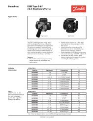
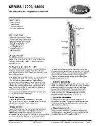
Single Gas Pressure Switch<br />
Each switch is adjustable within its ranges, as shown<br />
on the range scale on the front. The latch position in<br />
the reset type models, and lever indicator position in<br />
the recycle type models shows whether the switch is<br />
on or off.<br />
High Low Gas Pressure Switch<br />
Please read this instruction sheet carefully to assure<br />
correct installation. This equipment must be installed<br />
only by a licensed electrician who is experienced<br />
with combustion safeguard control systems and<br />
understands the functions of an interlocking switch<br />
such as gas pressure switches. Prior to being put<br />
into operation in conjunction with the combustion<br />
safeguard systems, all switches should be tested<br />
for proper range setting and proper wiring. Check<br />
piping connections and switch housing for leaks<br />
with a soap bubble test. All exhaust fans and<br />
blowers should be inspected and checked for<br />
proper rotation prior to starting up. If you have any<br />
problems or questions, phone, fax, email or write to<br />
the manufacturer, Antunes <strong>Controls</strong>.<br />
GDI 1010803D22 01/04<br />
LR
MODEL - D<br />
Electrical Ratings: All Models<br />
4A @125 VAC<br />
3A @250-277 VAC<br />
1/8 HP @125 VAC<br />
1/4 HP @ 250 VAC<br />
Pilot Duty - 125 VA, 125/250 VAC<br />
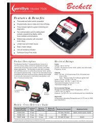
Electrical Wiring: Combination Models<br />
Model: HLGP-D<br />
Duty: High Low Gas Reset Switch<br />
Elec. Rating: 4A, 125 VAC, 3A, 250-277 VAC<br />
1/8 HP @125 VAC, 1/4 HP @ 250 VAC<br />
Pilot Duty: 125 VA, 125-250 VAC<br />
<br />
<br />
Model: RHLGP-D<br />
Duty: High Low Gas Reset Switch<br />
Elec. Rating: 4A, 125 VAC, 3A, 250-277 VAC<br />
1/8 HP @125 VAC, 1/4 HP @ 250 VAC<br />
Pilot Duty: 125 VA, 125-250 VAC<br />
R e s e t<br />
HLGP-D<br />
High Gas<br />
NC<br />
NO<br />
NC<br />
NO<br />
C<br />
C<br />
By Others<br />
Indicator On<br />
Indicator Off<br />
Reset lever will latch<br />
when gas pressure is<br />
below setting<br />
Reset lever will latch<br />
when gas pressure is<br />
above setting<br />
By Others<br />
Low Gas<br />
Field wiring to be rated @75ºC for max 120ºF Ambient<br />
Field wiring to be rated @90ºC for max 140ºF Ambient<br />
Max Surge Pressure: 10 PSIG<br />
R e s e t<br />
RHLGP-D<br />
High Gas<br />
NC<br />
NO<br />
NC<br />
NO<br />
C<br />
C<br />
By Others<br />
Indicator On<br />
Indicator Off<br />
Contacts C & NC<br />
break when pressure<br />
rises above setting<br />
Contacts C & NO<br />
make when pressure<br />
rises above setting<br />
By Others<br />
Low Gas<br />
Field wiring to be rated @75ºC for max 120ºF Ambient<br />
Field wiring to be rated @90ºC for max 140ºF Ambient<br />
Max Surge Pressure: 10 PSIG<br />
Electrical Wiring: Single Models<br />
Model: HGP-D<br />
Duty: High Gas Reset Switch<br />
Elec. Rating: 4A, 125 VAC, 3A, 250-277 VAC<br />
1/8 HP @125 VAC, 1/4 HP @ 250 VAC<br />
Pilot Duty: 125 VA, 125-250 VAC<br />
Model: LGP-D<br />
Duty: Low Gas Reset Switch<br />
Elec. Rating: 4A, 125 VAC, 3A, 250-277 VAC<br />
1/8 HP @125 VAC, 1/4 HP @ 250 VAC<br />
Pilot Duty: 125 VA, 125-250 VAC<br />
R e s e t<br />
HGP-D<br />
NC<br />
NO<br />
C<br />
Indicator On<br />
By Others<br />
Reset lever will latch<br />
when gas pressure is<br />
below setting contact<br />
C & NC make<br />
R e s e t<br />
LGP-D<br />
NC<br />
NO<br />
C<br />
Indicator Off<br />
By Others<br />
Reset lever will latch<br />
when gas pressure is<br />
above setting contact<br />
C & NO make<br />
Field wiring to be rated @75ºC for max 120ºF Ambient<br />
Field wiring to be rated @90ºC for max 140ºF Ambient<br />
Max Surge Pressure: 10 PSIG<br />
Field wiring to be rated @75ºC for max 120ºF Ambient<br />
Field wiring to be rated @90ºC for max 140ºF Ambient<br />
Max Surge Pressure: 10 PSIG<br />
Model: RHGP-D<br />
Duty: High Gas Recycle Switch<br />
Elec. Rating: 4A, 125 VAC, 3A, 250-277 VAC<br />
1/8 HP @125 VAC, 1/4 HP @ 250 VAC<br />
Pilot Duty: 125 VA, 125-250 VAC<br />
Model: RLGP-D<br />
Duty: Low Gas Recycle Switch<br />
Elec. Rating: 4A, 125 VAC, 3A, 250-277 VAC<br />
1/8 HP @125 VAC, 1/4 HP @ 250 VAC<br />
Pilot Duty: 125 VA, 125-250 VAC<br />
Recycle<br />
RHGP-D<br />
NC<br />
NO<br />
C<br />
Indicator On<br />
By Others<br />
Contacts C & NC<br />
break when pressure<br />
rises above setting<br />
Recycle<br />
RLGP-D<br />
NC<br />
NO<br />
C<br />
Indicator Off<br />
By Others<br />
Contacts C & NO<br />
make when pressure<br />
rises above setting<br />
Field wiring to be rated @75ºC for max 120ºF Ambient<br />
Field wiring to be rated @90ºC for max 140ºF Ambient<br />
Max Surge Pressure: 10 PSIG<br />
Field wiring to be rated @75ºC for max 120ºF Ambient<br />
Field wiring to be rated @90ºC for max 140ºF Ambient<br />
Max Surge Pressure: 10 PSIG
MODEL - D<br />
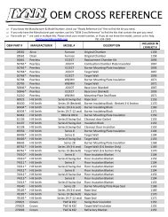
Mounting: Simple Mounting - All Models<br />
Single Model Mounting Bracket<br />
1/2”<br />
13 mm<br />
All Mounting Holes (Dia.)<br />
7/32” 5/16” 7/32”<br />
5.5 mm 8 mm 5.5 mm<br />
Double Model Mounting Bracket<br />
All Mounting Holes 5/16” (8mm) Diameter<br />
1/2”<br />
13 mm<br />
3 3/4”<br />
95 mm<br />
7/8”<br />
22 mm<br />
7/8”<br />
22 mm<br />
1”<br />
25 mm<br />
2”<br />
51 mm<br />
1”<br />
25 mm<br />
2 5/8”<br />
67 mm<br />
1 1/8”<br />
28 mm<br />
7/8”<br />
22 mm<br />
1/2”<br />
13 mm<br />
All gas pressure switches must be mounted in a horizontal<br />
position, with the inlet stem down. Switches should be<br />
reasonably level but do not require accurate leveling.<br />
Single gas switch models have a 1/4” N.P.T. gas inlet.<br />
Double combination Hi-Lo switches have a 3/8” N.P.T. for high<br />
pressure inlet and a 1/8” N.P.T. for low pressure inlet.<br />
Gas vent outlets are 1/8” N.P.T. on all models.<br />
Piping can be either standard black pipe or aluminum tubing.<br />
All switches can be supported by the inlet pipe, but optional<br />
mounting brackets are available if needed.<br />
All switches have been factory-calibrated and tested for leaks.<br />
However, it is recommended that after the installation is<br />
completed, switch, gas pipe inlets, and connections be tested<br />
for leaks with a soap bubble test.<br />
Maximum surge pressure: 10 PSIG<br />
Maximum ambient operating temperature: 140°F or 60°C<br />
Minimum ambient operating temperature: -40°F or -40°C<br />
Operation<br />
Low Gas Pressure<br />
Low gas pressure switches break the electrical circuit<br />
on pressure drop at the point when gas pressure<br />
becomes lower than the indicated set pressure.<br />
Before the manual reset latch can be properly latched,<br />
gas pressure in the chamber must be higher than the<br />
indicated setting. The position of the reset latch on the<br />
top cover of the switch shows whether reset latch is<br />
in the on or off position. Reset latch must be in “on”<br />
position after latching to be properly set.<br />
High Gas Pressure<br />
High gas pressure switches break the electrical circuit<br />
when pressure rises above the indicated preset<br />
pressure. The reset latch should be latched in the “on”<br />
position if the gas pressure in the switch chamber is<br />
below the indicated high setting.<br />
Recycle Models<br />
High and Low Gas Pressure<br />
Recycle models operate automatically and do not need<br />
to be reset. Otherwise they are constructed, adjusted,<br />
and operate in the same manner as the reset models.<br />
Combination Models<br />
The combination unit contains one high pressure unit<br />
and one low pressure unit, in the ranges you select.<br />
They may be either reset or recycle type. Each unit has<br />
on/off indicator, and its own range scale indicator.<br />
Reset Latch<br />
Range Scale
Model Numbers<br />
Reset<br />
Recycle<br />
HLGP-D Combination Double Unit RHLGP-D<br />
LGP-D Single Unit, Lo-Pressure RLGP-D<br />
HGP-D Single Unit, Hi-Pressure RHGP-D<br />
Ranges Available<br />
High Gas Pressure<br />
(HGP-D, RHGP-D)<br />
Low Gas Pressure<br />
(LGP-D, RLGP-D)<br />
W.C. mm/W.C. W.C. mm/W.C.<br />
5 - 28” W.C. 125-700 2-14” W.C. 50-350<br />
10 - 50” W.C. 250-1250 10-50” W.C. 250-1250<br />
To order: For example, if you<br />
wanted a switch with a low<br />
pressure cut-off at 4” reset type,<br />
you would order Model LGP-D<br />
1-6”. If you wanted a combination<br />
switch with a high pressure cut-off<br />
at 40” W.C. and a low pressure<br />
cut-off at 8” W.C. in recycle type,<br />
you would order Model RHLGP-D<br />
10-50”, 2-14”.<br />
Dimensions: High Low Gas Pressure Switch<br />
Front<br />
Dimensions: Single Gas Pressure Switch<br />
Front<br />
4 1/4”<br />
(108 mm)<br />
1/8” NPT<br />
Gas Vent<br />
4 1/16”<br />
(103 mm)<br />
5 5/8”<br />
(143 mm)<br />
Side<br />
1/8” NPT<br />
High Pressure<br />
Inlet<br />
5 3/8”<br />
(136 mm)<br />
1/8” NPT<br />
Low Pressure<br />
Gas Vent<br />
4 1/16”<br />
(103 mm)<br />
Inlet 1/4” NPT<br />
Vent 1/8” NPT<br />
4 1/16”<br />
(103 mm)<br />
It is understood and agreed that seller’s liability whether in<br />
Limitation of Liability<br />
The price stated for the equipment is a consideration in limiting<br />
contract, in tort, under any warranty, in negligence or otherwise<br />
shall not exceed the return of the amount of the purchase<br />
price paid by purchaser and under no circumstances shall<br />
seller’s liability. No action, regardless of form, arising out of the<br />
transactions may be brought by purchaser more than one year<br />
after the cause of action has accrued.<br />
seller be liable for special, indirect or consequential damages.<br />
180 Kehoe Boulevard Carol Stream, Illinois 60188 • USA • Ph: (630) 784-1000 • (800) 253-2991•Fx:(630) 784-1650<br />
www.ajantunes.com