L7224U Oil Electronic Aquastat® Controller - Patriot Supply
L7224U Oil Electronic Aquastat® Controller - Patriot Supply
L7224U Oil Electronic Aquastat® Controller - Patriot Supply

You also want an ePaper? Increase the reach of your titles
YUMPU automatically turns print PDFs into web optimized ePapers that Google loves.
<strong>L7224U</strong><br />
<strong>Oil</strong> <strong>Electronic</strong> Aquastat ® <strong>Controller</strong><br />
APPLICATION<br />
The EnviraCOM enabled <strong>L7224U</strong> <strong>Oil</strong> <strong>Electronic</strong><br />
Aquastat ® <strong>Controller</strong> provides electronic temperature<br />
sensing in a UL limit-rated controller with a single<br />
sensing probe. The <strong>L7224U</strong> controls the circulator, oil<br />
burner and boiler temperature.<br />
The <strong>L7224U</strong> is “Outdoor Temperature Reset” ready,<br />
which is enabled when connected to the 50022037-002<br />
Outdoor Reset Module. (option 1)<br />
Additionally, the <strong>L7224U</strong> provides adjustable short cycle.<br />
The <strong>L7224U</strong> replaces the L8124A, L8124C, L7124U,<br />
L7148A, L7248A,C, L7224A,C, and L8148A <strong>Controller</strong>s.<br />
The Aquastat <strong>Controller</strong> is intended for use in residentialtype<br />
applications.<br />
The <strong>L7224U</strong> provides status and diagnostic information<br />
through an LED display combined with LED lights as well<br />
as EnviraCOM enabled thermostats and diagnostic tools<br />
to enhance the diagnostic process.<br />
SPECIFICATIONS<br />
Electrical Ratings:<br />
Voltage: 120 Vac, 60 Hz.<br />
Power: 7 VA maximum at 120 Vac plus external loads.<br />
Thermostat current: 100 mA nominal at 24 Vac.<br />
Burner Relay:<br />
7.4 A at 120 Vac Full Load Amperage (FLA);<br />
44.4 A inrush Locked Rotor Amperage (LRA);<br />
Less Ignition Load: 360 VA.<br />
Circulator Relay:<br />
7.4 A at 120 Vac FLA; 44.4 A inrush LRA.<br />
Zone <strong>Controller</strong> (ZC): 7.4 A at 120 Vac FLA;<br />
44.4 A inrush LRA.<br />
INSTALLATION INSTRUCTIONS<br />
Accessories (Ordered Separately):<br />
50022037-002 AquaReset Outdoor Reset Module<br />
C7089U1006 Outdoor Temperature Sensor (used with<br />
the 50022037-002)<br />
W8735S1000 (AquaReset Outdoor Reset Kit) includes<br />
50022037-002 and C7089U1006)<br />
50022037-005 Domestic Hot Water Module<br />
32003971-003 Temperature Sensor (used with<br />
50022037-005)<br />
W8735S1008 AquaReset Domestic Hot Water Kit<br />
(includes 50022037-005 and 32003971-003)<br />
Sensor (See Table 2).<br />
Sensor Well Clamp 121371AA.<br />
14,000,485-016 1/4 in. (6.35 mm) diameter, 1-1/4 in.<br />
(31.75 mm) length glass cartridge Fuse, 1 A,<br />
Slow-Blow.<br />
120650 Heat Conductive Compound.<br />
Part<br />
Number<br />
Table 1. Wells for <strong>L7224U</strong> <strong>Controller</strong>.<br />
Spud Size<br />
in. (mm)<br />
Insertion<br />
in. (mm)<br />
Insulation<br />
in. (mm)<br />
123869A 1/2 (12.7) NPT 3 (76.2) 1-1/2 (38.1)<br />
123870A 3/4 (19.05) NPT 3 (76.2) 1-1/2 (38.1)<br />
Table 2. Sensors for <strong>L7224U</strong> <strong>Controller</strong>.<br />
Part Number<br />
Length in.<br />
(mm) Application<br />
50001464-001 12 (304.8) Well-mounted controls<br />
50001464-002 18 (457.2) Flush-mounted controls<br />
50001464-003 24 (609.6)<br />
50001464-004 36 (914.4)<br />
50001464-005 48 (1219.2)<br />
NOTE:<br />
All loads combined cannot exceed 2000 VA.<br />
Environmental Ratings:<br />
Temperature: -30° F to +150° F (-34° C to +66° C).<br />
Humidity: 0 to 95% relative humidity, noncondensing.<br />
Approvals:<br />
Underwriters Laboratories Inc. Component Recognized.<br />
Canadian Underwriters Laboratories Inc. Component<br />
Recognized.<br />
69-1720-03
<strong>L7224U</strong> OIL ELECTRONIC AQUASTAT ® CONTROLLER<br />
INSTALLATION<br />
When Installing this Product...<br />
1. Read these instructions carefully. Failure to follow<br />
them could damage the product or cause a hazardous<br />
condition.<br />
2. Check the ratings given in the instructions and on<br />
the product to make sure the product is suitable for<br />
your application.<br />
3. The installer must be a trained, experienced service<br />
technician.<br />
4. After installation is complete, check out product<br />
operation as provided in these instructions.<br />
5. Set High Limit, Low Limit and Differential to the settings<br />
recommended by the boiler OEM.<br />
6. Record the maximum High Limit setting from the<br />
replaced controller in the text box provided on the<br />
cover insert label.<br />
7. Record the High Limit setting at the time of installation<br />
in the text box provided on the cover insert<br />
label.<br />
WARNING<br />
Electrical Shock Hazard.<br />
Can cause severe injury, death or property<br />
damage.<br />
Disconnect power supply before beginning<br />
installation to prevent electrical shock or<br />
equipment damage.<br />
Mounting<br />
The <strong>L7224U</strong> can be mounted in a well mount, horizontal<br />
or vertical position, or flush mounted remote from the well.<br />
IMPORTANT<br />
Immersion well must fit sensing element and<br />
sensor must rest against bottom of well.<br />
New Installation<br />
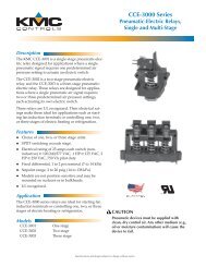
Order well assemblies separately; refer to Table 1 and<br />
form no. 68-0040, Immersion Wells and Compression<br />
Fittings for Temperature <strong>Controller</strong>s. Boilers usually have<br />
tappings that allow the well to be mounted horizontally so<br />
boiler water of average temperature can circulate freely<br />
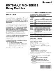
over the well. See Fig. 1 for mounting dimensions.<br />
3/4<br />
(75)<br />
7-1/8<br />
(181)<br />
6-1/2<br />
(166)<br />
5-11/16<br />
(145)<br />
3-1/32<br />
(77)<br />
3/8<br />
(10)<br />
1-3/16<br />
(30)<br />
1-1/8 (29)<br />
2-5/8 (67)<br />
4-1/4 (109)<br />
3-13/32 (86)<br />
2x 1/4 (7) x 3/8 (9)<br />
1/16 (2)<br />
2-1/16 (53)<br />
M22147B<br />
Fig. 1. <strong>L7224U</strong> mounting dimensions in inches (mm).<br />
1. Turn off all power and drain the boiler.<br />
2. If no tapping is provided, prepare properly sized and<br />
threaded tapping near the top of the boiler.<br />
3. Sparingly coat the well threads with pipe dope.<br />
NOTE:<br />
Do not attempt to tighten by using the case as a<br />
handle.<br />
4. Install the well in the boiler tapping and tighten<br />
securely.<br />
5. Refill boiler and check for water leakage.<br />
6. Identify if installation requires vertical or horizontal<br />
mounting.<br />
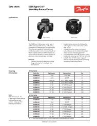
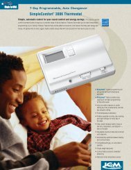
7. Remove the well knockout, for either vertical or<br />
horizontal mounting, by carefully prying the<br />
knockout from the back of the case, using a<br />
flat-bladed screw driver. Refer to Fig. 2.<br />
69-1720—03 2
<strong>L7224U</strong> OIL ELECTRONIC AQUASTAT ® CONTROLLER<br />
SENSOR WIRES<br />
CONTROLLER CASE<br />
BOILER<br />
KNOCKOUT FOR<br />
HORIZONTAL<br />
MOUNT<br />
IMMERSION<br />
WELL<br />
SENSOR<br />
SCREWDRIVER<br />
KNOCKOUT FOR<br />
VERTICAL MOUNT<br />
M22118<br />
Fig. 2. Removing horizontal or vertical mounting<br />
knockout.<br />
8. Loosen but do not remove the well clamp screw.<br />
9. Fit the case into the well so the clamp on the case<br />
slides over the flange on the well.<br />
10. Securely tighten the clamp screw.<br />
11. Insert the sensor element into the well until it<br />
bottoms. (If necessary, slightly bend the wire inside<br />
the case to hold the sensor against the bottom of<br />
the well.)<br />
12. Turn power ON.<br />
13. Set High Limit, Low Limit and Differentials to the<br />
settings recommended by the boiler OEM. (See<br />
OPERATION section, also refer to INSTALLATION<br />
steps 6 and 7.)<br />
IMPORTANT<br />
Best thermal response is obtained with a well<br />
that snugly fits the sensor. Insert the sensor until<br />
it rests against the bottom of the well. Use a well<br />
of correct length and bend the wiring, if necessary,<br />
to hold the bulb against the bottom of the<br />
well.<br />
If the well is not a snug fit on the sensor, use the<br />
heat-conductive compound (furnished with<br />
TRADELINE ® models) as follows: Fold the<br />
plastic bag of compound lengthwise and twist it<br />
gently. Then snip off end of bag and work the<br />
open end of the bag all the way into the well.<br />
Slowly pull out the bag while squeezing it firmly<br />
to distribute compound evenly in the well. Bend<br />
the wiring, if necessary, to hold the sensor<br />
against the bottom of the well and to hold outer<br />
end of the sensor in firm contact with the side of<br />
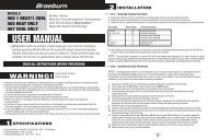
the well. See Fig. 3. Wipe excess compound<br />
from the outer end of the well.<br />
IMMERSION<br />
WELL CLAMP<br />
IMMERSION WELL<br />
CLAMP SCREW<br />
HEAT-CONDUCTIVE COMPOUND<br />
(OPTIONAL)<br />
M16120<br />
Fig. 3. Position of sensor in immersion well.<br />
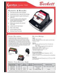
Flush-Mounted Aquastat Replacement<br />
Turn off all power and remove the old controller. Refer to<br />
the cover insert of the old controller to identify and tag<br />
each external lead as it is disconnected. If the old well is<br />
unsuitable for the new installation, remove it and replace it<br />
with a suitable new well. If the old well is suitable, use it.<br />
See Fig. 1 and 4 for mounting tab location.<br />
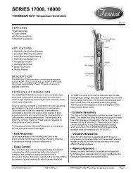
ZR<br />
L1<br />
L2<br />
C2<br />
B2<br />
C1<br />
B1<br />
ZC<br />
LINE<br />
THERMOSTAT<br />
TERMINALS<br />
TX<br />
TT<br />
FLUSH MOUNTING TAB (2)<br />
T<br />
T 3<br />
2<br />
1<br />
B1 ZC C1<br />
ENVIRACOM TM<br />
TERMINALS<br />
DISPLAY<br />
LED's<br />
CAPACITOR<br />
SENSOR<br />
CONNECTOR<br />
RELAYS<br />
TRANSFORMER<br />
SENSOR HOLES<br />
FUSE<br />
RELAY<br />
M22119A<br />
Fig. 4. Location of <strong>L7224U</strong> flush-mounting tabs and<br />
LEDs.<br />
3 69-1720—03
<strong>L7224U</strong> OIL ELECTRONIC AQUASTAT ® CONTROLLER<br />
Well-Mounted Aquastat Replacement<br />
Turn off all power and remove the old controller. Refer to<br />
the cover insert of the old controller to identify and tag<br />
each external lead as it is disconnected. If the old well is<br />
unsuitable for the new installation, remove it and proceed<br />
with instructions for new installation. If the old well is<br />
suitable, use it.<br />
1. Loosen, but do not remove, the well clamp screw on<br />
the side of the controller case.<br />
2. Position immersion well clamp snugly over the<br />
flange of the adapter and tighten the clamp screw.<br />
3. Insert the sensor into the well as shown in Fig. 5.<br />
(If desired, distribute the heat-conductive compound<br />
in the tube prior to sensor insertion, as<br />
described in New Installation.)<br />
4. Make sure sensor is fully seated to bottom of well<br />
(Fig. 5). Use a small pencil to measure depth of<br />
sensor in well, if necessary.<br />
SENSOR WIRES<br />
BOILER<br />
IMMERSION<br />
WELL<br />
SENSOR<br />
IMPORTANT<br />
The terminals on these Aquastat <strong>Controller</strong>s are<br />
approved for use with copper wire only.<br />
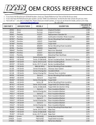
Follow the appropriate wiring diagrams shown on the<br />
inside of the front cover of the <strong>L7224U</strong> or in Fig. 9, 10, and<br />
11.<br />
Refer to Fig. 6 for Connections for the optional Outdoor<br />
Reset Module and the Domestic Hot Water (DHW)<br />
module. In subsequent wiring diagrams these modules<br />
will be displayed with a dotted line signifying that they are<br />
optional.<br />
ZR<br />
L1<br />
L2<br />
LINE<br />
T<br />
T 3<br />
2<br />
1<br />
50022037-002<br />
OUTDOOR<br />
RESET MODULE<br />
1 2 3 OT OT<br />
C7089U1006<br />
OUTDOOR<br />
SENSOR<br />
50022037-005<br />
DOMESTIC HOT<br />
WATER MODULE<br />
C2<br />
Fig. 5. Replacement sensor installation.<br />
Replacement Sensor Installation<br />
Turn off all power and carefully disconnect sensor from<br />
circuit board by pulling gently on the connector.<br />
1. Gently pull sensor from thermo well and through circuit<br />
board by pulling on leadwires.<br />
2. Carefully align replacement sensor with hole in<br />
circuit board and guide through Aquastat case and<br />
into well. Refer to Fig. 5.<br />
3. Make sure sensor is fully seated to bottom of well<br />
(see Fig. 5). Use a small pencil to measure depth of<br />
sensor in well, if necessary.<br />
4. Connect sensor to circuit board by pressing<br />
connector on sensor unit into mating connector on<br />
circuit board (refer to Fig. 6).<br />
5. For remote sensors (flush mounted Aquastat) be<br />
sure to use the 121371AA clamp to securely hold<br />
sensor in place. See Accessories.<br />
WIRING<br />
HEAT-CONDUCTIVE COMPOUND<br />
(OPTIONAL)<br />
M22026<br />
WARNING<br />
Electrical Shock Hazard.<br />
Can cause serious injury or death.<br />
Disconnect power supply before making wiring<br />
connections to prevent electrical shock or<br />
equipment damage.<br />
All wiring must comply with local electrical codes and<br />
ordinances. Do not exceed the specifications in the<br />
Application section when wiring this controller.<br />
B2<br />
C1<br />
B1<br />
ZC<br />
Fig. 6. Wiring the Outdoor Reset Module and the<br />
Domestic Hot Water Module.<br />
OPERATION<br />
1 2 3 TS TS<br />
32003971-003<br />
TEMPERATURE<br />
SENSOR<br />
M29651<br />
General<br />
The <strong>L7224U</strong> <strong>Oil</strong> <strong>Electronic</strong> Aquastat <strong>Controller</strong> is a<br />
primary safety limit-rated device designed for use with oil<br />
fired boilers with line voltage burners and circulators.<br />
Many boilers do not include wiring or controller<br />
compartments as part of the design, but are provided with<br />
an integral, replaceable, immersion well that is the<br />
mounting hardware for the Aquastat <strong>Controller</strong>s. Wiring to<br />
the other controllers is done through flexible metal<br />
conduit.<br />
For boilers that do include a remotely (flush) mounted<br />
controller, the wiring may be completed with conduit or<br />
routed behind the boiler sheet metal.<br />
A separate electromechanical High Limit is not required in<br />
a system that uses this controller to meet Underwriters<br />
Laboratories Inc. requirements for oil-fired boiler<br />
assemblies, UL 726.<br />
On the <strong>L7224U</strong>, the High Limit, High Limit Differential,<br />
Low Limit, and Low Limit Differential and Anti-Short Cycle<br />
time can be adjusted to the setting recommended by the<br />
boiler OEM.<br />
69-1720—03 4
<strong>L7224U</strong> OIL ELECTRONIC AQUASTAT ® CONTROLLER<br />
The overall range of the High Limit is from 130° F to<br />
240° F (54° C to 116° C). Select devices may have<br />
different ranges. Some models have limited ranges on the<br />
High Limit setpoint; this limited range is listed on the<br />
device label.<br />
The range of the Low Limit is from 110° F to 220° F<br />
(43° C to 104° C). Select devices may have different<br />
ranges. The range of the Anti-Short Cycle time is from 10<br />
seconds to five minutes.<br />
If a 50022037-002 “Outdoor Reset Module” is installed,<br />
the reset curve can be set by entering the minimum<br />
outdoor temperature, minimum (water or boiler)<br />
temperature, and maximum outdoor temperature on the<br />
3-digit display. The range of the minimum outdoor<br />
temperature is from -40°F to 40°F (-40°C to 4.4°C) and<br />
has a default setting of 0°F (-18°C). The range of the<br />
maximum outdoor temperature is from 30°F to 70°F (-1°C<br />
to 21°C) and has a default setting of 40°F (4.4°C). The<br />
range of the minimum (water or boiler) temperature is<br />
from 80°F to 180°F (27°C to 82°C) and has a default<br />
setting of 130°F (54°C). See the “Outdoor Reset Module”<br />
Installation Instructions (form number 69-2335) for more<br />
information on setting the boiler reset curve and all related<br />
parameters.<br />
The <strong>L7224U</strong> is designed for use with 24 Vac electronic<br />
and electromechanical thermostats and EnviraCOM<br />
enabled thermostats, and have screw-type terminals for<br />
easy field connection.<br />
To replace a L8148A,C L7148A or L7248A,C controller,<br />
the Low Limit function must be disabled; see Adjusting<br />
Settings for directions.<br />
Adjusting Settings<br />
To discourage unauthorized changing of Aquastat<br />
settings, a procedure to enter the ADJUSTMENT mode is<br />
required. To enter the ADJUSTMENT mode, press the<br />
UP, DOWN, and I buttons (refer to Fig. 9) simultaneously<br />
for three seconds. Press the I button until the feature<br />
requiring adjustment is displayed:<br />
• HL_ — High Limit.<br />
• Hdf — High Limit Differential.<br />
• LL_ — Low Limit.<br />
• Ldf — Low Limit Differential.<br />
• duu — ZR input configured as external Domestic Hot<br />
Water (DHW) request (ON/OFF)<br />
• ASC — Anti Short-Cycle Timeout (seconds); “OFF” is<br />
disabled.<br />
• otL — Outdoor Temperature Low (minimum)<br />
parameter for the outdoor reset curve (F or C)*<br />
• otH — Outdoor Temperature High (maximum)<br />
parameter for outdoor reset curve (F or C)*<br />
• btL — Boiler Temperature Low (minimum) parameter<br />
for outdoor reset curve*<br />
• bP — Boost Period (minutes). “OFF” is displayed if<br />
Boost is inactive*<br />
• bS — Boost step (F or C) shown only if Boost is active<br />
(bP=ON)*<br />
• UUS — Warm Weather Shutdown Temperature (F or<br />
C)*<br />
• F-C — Temperature units (F or C)<br />
* Settings available for adjustment on the 3-digit display<br />
only if the AquaReset Outdoor Reset Module is installed.<br />
Then press the UP and/or DOWN buttons to move the set<br />
point to the desired value. After 60 seconds without any<br />
button inputs, the controller will automatically return to the<br />
RUN mode.<br />
To use the <strong>L7224U</strong> in a cold start boiler application,<br />
disable the Low Limit function by pressing the UP arrow<br />
button, DOWN arrow button and I button simultaneously<br />
for three seconds. Then push the I button until LL_ is<br />
displayed. Then press the down arrow button until OFF is<br />
displayed.<br />
Display<br />
In the RUN mode, the Aquastat will flash “bt” (boiler temp)<br />
followed by the temperature (i.e., 220), followed by °F or<br />
°C.<br />
To read boiler settings, press the I key to read the<br />
parameter of interest. For example, press I and HL (High<br />
Limit) is displayed, followed by a three-digit number, i.e.,<br />
220, followed by °F or °C. Pressing the I button again will<br />
display the LL (Low Limit) followed by a three-digit<br />
number and the corresponding degree designator. See<br />
Fig. 7 for explanation of display readout.<br />
After approximately 60 seconds without any key presses,<br />
the display will enter a dim display mode. To return to the<br />
bright display mode, simply press and release any key.<br />
5 69-1720—03
<strong>L7224U</strong> OIL ELECTRONIC AQUASTAT ® CONTROLLER<br />
Text<br />
Err<br />
bt<br />
HdF<br />
LL<br />
Ldf<br />
tt<br />
ttE<br />
brn<br />
Cir<br />
ZC<br />
Zr<br />
Description<br />
Boiler Temperature<br />
High Limit Differential<br />
Low Limit (L7224 only)<br />
Low Limit Differential (L7224 only)<br />
Local Thermostat Status<br />
EnviraCOM Thermostat Status<br />
ELL External Low Limit Enabled (L7248L only)<br />
duu ZR Configured as Domestic Hot Water<br />
Request (L7224, L7248L only)<br />
ASC Anti Short-Cycle Timeout<br />
bSP 2 Boiler Setpoint<br />
dhc 3 DHW Module Connected (YES or NO)<br />
ot 2 Outdoor Temperature<br />
otL 2 Outdoor Temperature Low<br />
otH 2 Outdoor Temperature High<br />
btL 2 Boiler Temperature Low<br />
bP 2 Boost Period<br />
Fig. 7. Explanation of display readout.<br />
*Settings viewable on the 3-digit display only if the<br />
“Outdoor Reset Module” is installed.<br />
Display<br />
Shows<br />
bS 2 Boost Step<br />
UUS 2 Warm Weather Shutdown Temperature<br />
°F Units are displayed in degrees Fahrenheit<br />
°C Units are displayed in degrees Celsius<br />
OFF Input or Output is OFF<br />
On Input or Output is ON<br />
1 DISPLAY SHOWS LOCAL SETTING; NOT THE SETTING<br />
AS MODIFIED BY AN EXTERNAL ENVIRACOM CONTROL.<br />
2<br />
3<br />
Error Code (if one is present)<br />
HL 1 High Limit<br />
B1 (Burner) output (ON or OFF)<br />
C1 (Circulator) output (ON or OFF)<br />
ZC (Zone Control) output (ON or OFF)<br />
ZR (Zone Request) Call for HEAT (ON or OFF)<br />
SETTINGS ARE VIEWABLE ONLY IF THE OUTDOOR<br />
RESET MODULE AND OUTDOOR TEMPERATURE<br />
SENSOR ARE INSTALLED AND FUNCTIONING PROPERLY.<br />
SETTINGS ARE VIEWABLE ONLY IF THE DOMESTIC<br />
HOT WATER MODULE AND SENSOR ARE INSTALLED<br />
AND FUNCTIONING PROPERLY.<br />
M29552<br />
Operation<br />
The <strong>L7224U</strong> can be in any of four operational states:<br />
Normal, High Limit, Low Limit and Error. The controller<br />
moves back and forth from High Limit to Normal to Low<br />
Limit state as part of normal operation. The operating<br />
states are:<br />
1. Normal: Boiler temperature went below the High<br />
Limit setting (minus the Differential) and has not<br />
exceeded the High Limit setting; or, the boiler temperature<br />
went above the Low Limit setting and has<br />
not gone below the Low Limit setting (minus the Differential).<br />
2. High Limit: Boiler temperature went above the High<br />
Limit setting and has not dropped below the High<br />
Limit setting (minus the Differential).<br />
3. Low Limit: Boiler temperature went below the Low<br />
Limit setting (minus the Low Limit Differential) and<br />
has not gone above the Low Limit setting.<br />
4. Error: The controller has detected an error condition<br />
(e.g., open sensor) and has shut down the burner<br />
output. The Zone Control (ZC) output is energized.<br />
The controller continues to monitor the system and<br />
automatically restarts if the error condition clears.<br />
Refer to Table 4–6.<br />
The operating sequence for the <strong>L7224U</strong> is shown in Table<br />
3.<br />
High Limit <strong>Controller</strong><br />
The High Limit opens and turns off the burner when the<br />
water temperature reaches the setpoint. The High Limit<br />
automatically resets after the water temperature drops<br />
past the setpoint and through the adjustable Differential.<br />
Low Limit and Circulator <strong>Controller</strong><br />
On a temperature rise, the burner circuit breaks and the<br />
circulator circuit makes (assuming no call for heat is<br />
present) at the Low Limit setpoint. On a temperature drop<br />
of 10° F (6° C) below the Low Limit setpoint (with the<br />
adjustable Differential at the minimum setting of 10° F<br />
(6° C)), the burner circuit makes and the circulator circuit<br />
breaks. Refer to Fig. 7.<br />
HIGH LIMIT<br />
SETTING<br />
LOW LIMIT<br />
SETTING<br />
10ºF (6ºC)<br />
DIFFERENCE<br />
10ºF (6ºC)<br />
DIFFERENCE<br />
SWITCH BREAKS ON<br />
TEMPERATURE RISE.<br />
BURNER TURNS OFF.<br />
CIRCULATOR OPERATES<br />
ON A CALL FOR HEAT.<br />
SWITCH MAKES ON<br />
TEMPERATURE FALL.<br />
BURNER OPERATES ON A<br />
CALL FOR HEAT.<br />
WITH NO HEATING<br />
DEMAND, SWITCH BREAKS<br />
ON TEMPERATURE RISE.<br />
1<br />
SWITCH MAKES ON<br />
TEMPERATURE FALL,<br />
BURNER IS ON TO<br />
MAINTAIN MINIMUM<br />
WATER TEMPERATURE.<br />
CIRCULATOR IS OFF.<br />
1 WHEN WATER REACHES LOW LIMIT SETTING, THE BURNER SHUTS<br />
OFF OR THE CIRCULATOR PUMP STARTS (WHEN CALLING FOR HEAT).<br />
M23365<br />
Fig. 8. Setpoints and differentials.<br />
69-1720—03 6
<strong>L7224U</strong> OIL ELECTRONIC AQUASTAT ® CONTROLLER<br />
NOTE:<br />
Setting the Low Limit above the High Limit less<br />
the High Limit Differential is not allowed as<br />
improper circulator and Zone Control functions<br />
could result.<br />
Anti Short-Cycle Feature<br />
The Anti Short-Cycle feature allows for field selection of a<br />
minimum delay time between burner cycles. Should a call<br />
for heat occur following the end of the previous heat cycle<br />
and before the Anti-Short Cycle delay time is expired, the<br />
circulator will be allowed to run, but the burner will be held<br />
off until the time has elapsed.<br />
TROUBLESHOOTING<br />
When attempting to diagnose system performance,<br />
reference to the LED display can help to identify specific<br />
areas not working properly. The LED display will scroll<br />
Err, followed by a digit (1-8). Refer to Table 7 for a<br />
description of each error and suggested actions and Table<br />
8 for a troubleshooting guide.<br />
L1<br />
(HOT)<br />
L2<br />
NOTE:<br />
The Anti Short-Cycle feature is blocked if DHW<br />
demand occurs. DHW demands are serviced<br />
immediately, without any delay.<br />
T<br />
T 3<br />
2<br />
1<br />
NOTE:<br />
When the Aquastat is connected to the oil primary<br />
and/or thermostat via the EnviraCOM bus,<br />
the Anti Short-Cycle time does not apply to recycle<br />
events such as loss of airflow or flame. It<br />
applies only to loss of demand.<br />
SENSOR<br />
ZR<br />
LINE<br />
ZR-Domestic Hot Water (DHW) Request<br />
The ZR terminal on the <strong>L7224U</strong> can be selected to<br />
service an indirect water heater heat request. This<br />
parameter is set via the 3 digit display (see Adjusting<br />
Settings section of this document). A heat request via the<br />
ZC terminal will have priority over all other features such<br />
as the Anti-Short Cycle feature or those enabled by the<br />
Outdoor Reset Module (See form69-2235 for more<br />
information).<br />
LINE<br />
VOLTAGE<br />
CIRCULATOR<br />
LINE<br />
VOLTAGE<br />
OIL BURNER<br />
RELAY<br />
L1<br />
L2<br />
C2<br />
B2<br />
C1<br />
B1<br />
ZC<br />
M22028A<br />
CHECKOUT<br />
Fig. 9. <strong>L7224U</strong> single zone connections.<br />
Put the system into operation and observe at least one<br />
complete cycle to make sure that the controller operates<br />
properly. See TROUBLESHOOTING section to use LED<br />
to assist in determining system operation.<br />
7 69-1720—03
<strong>L7224U</strong> OIL ELECTRONIC AQUASTAT ® CONTROLLER<br />
Table 3. L7224/L7248 <strong>Controller</strong> Operating Sequence.<br />
Action<br />
System Response<br />
Thermostat Circulator starts when water temperature is<br />
calls for heat. above Low Limit setting (if applicable).<br />
Boiler temperature is checked. Burner<br />
starts when water temperature is below<br />
High Limit setting.<br />
If Anti-short Cycle Time is enabled, the<br />
burner does not start until the set Antishort<br />
Cycle Time between cycles expires<br />
after the previous call for heat was<br />
satisfied.<br />
Boiler<br />
temperature<br />
exceeds the<br />
High Limit.<br />
Thermostat is<br />
satisfied.<br />
Boiler<br />
temperature<br />
drops below<br />
the Low Limit<br />
setting minus<br />
the<br />
differential (if<br />
applicable).<br />
Error<br />
conditions<br />
1-5.<br />
Error<br />
condition 6.<br />
Error<br />
condition 7.<br />
Error<br />
condition 8.<br />
Error<br />
condition 9*.<br />
Burner is turned off. Burner restarts when<br />
the water temperature drops below the<br />
High Limit setting minus the Differential.<br />
Circulator and burner turn off.<br />
Burner is turned on, Circulator is turned<br />
off. Burner stops when the water<br />
temperature exceeds the Low Limit<br />
setting.<br />
If an error condition is detected, all outputs<br />
except ZC are shut down. Burner is off.<br />
The controller continues to function and<br />
restarts when error is corrected.<br />
During the error check sequence, the<br />
system checks for drift in the sensor and<br />
corrosion in the connections.<br />
EnviraCOM communication is not<br />
available.<br />
The controller has reset the High Limit,<br />
Low Limit and Differential Setting to a<br />
default setting and will continue to run at<br />
those settings. Performance of the system<br />
will be degraded.<br />
If the error condition is detected, all<br />
outputs except ZC are shut down. Burner<br />
is off.The controller continues to function<br />
and restarts when all three user keys have<br />
been pressed longer than 60 seconds.<br />
System continues to run with no outdoor<br />
reset functionality<br />
Error System continues to run with outdoor reset<br />
condition 10*. parameters enabled as programmed.<br />
Error cleared automatically.<br />
Error System continues to run with boiler temp<br />
condition 11*. set to High Limit.<br />
* Error condition only available when the Outdoor Reset<br />
Module is installed.<br />
Table 4. L7224 <strong>Controller</strong> Operating Sequence with<br />
multiple zones connected through the ZR terminal<br />
Action<br />
System Response<br />
Zone Request (ZR)<br />
terminal is<br />
connected to L1<br />
(Zone calls for<br />
heat).<br />
Boiler temperature<br />
exceeds the High<br />
Limit.<br />
Zone Request input<br />
is de-energized<br />
(Zones are<br />
satisfied).<br />
Boiler temperature<br />
drops below the<br />
Low Limit setting<br />
minus the<br />
differential (if<br />
applicable).<br />
Boiler temperature is checked.<br />
Burner starts when water<br />
temperature is below High Limit<br />
setting. Anti Short-Cycle Time is<br />
applied, see Table 3.<br />
Burner is turned off. Burner restarts<br />
when the water temperature drops<br />
below the High Limit setting minus<br />
the Differential.<br />
Burner turns off.<br />
Burner turns on and Zone Control<br />
is de-energized. Burner turns off<br />
and Zone Control is re-energized<br />
when the water temperature<br />
exceeds the Low Limit setting.<br />
Table 5. <strong>Controller</strong> Operating Sequence with External<br />
Low Limit device connected trough the ZR terminal.<br />
Action<br />
System Response<br />
Zone Request (ZR)<br />
terminal is<br />
connected to L1<br />
(External Low Limit<br />
call for heat).<br />
Boiler temperature<br />
exceeds the High<br />
Limit.<br />
Zone Request input<br />
is de-energized<br />
(External Low Limit<br />
is satisfied).<br />
Boiler temperature is checked.<br />
Burner starts when water<br />
temperature is below High Limit<br />
setting. Circulator turns off.<br />
Burner is turned off. Burner restarts<br />
when the water temperature drops<br />
below the High Limit setting minus<br />
the Differential.<br />
Burner is turned off.<br />
Table 6. L7224 <strong>Controller</strong> Operating Sequence with<br />
Domestic Hot Water connected trough the ZR<br />
terminal.<br />
Action<br />
System Response<br />
Zone Request (ZR)<br />
terminal is connected to<br />
L1 (Domestic Hot Water<br />
calls for heat).<br />
Boiler temperature<br />
exceeds the High Limit.<br />
Zone Request input is<br />
de-energized (Domestic<br />
Hot Water is satisfied).<br />
Boiler temperature is checked.<br />
Burner starts when water<br />
temperature is below High<br />
Limit setting.<br />
Burner is turned off. Burner<br />
restarts when the water<br />
temperature drops below the<br />
High Limit setting minus the<br />
Differential.<br />
Burner is turned off.<br />
69-1720—03 8
Aquastat<br />
Error<br />
Code<br />
Table 7. LED Error Codes.<br />
<strong>L7224U</strong> OIL ELECTRONIC AQUASTAT ® CONTROLLER<br />
Cause/Action<br />
Err1 Aquastat sensor fault; check water sensor. 18<br />
Err2 ECOM fault; check EnviraCOM wiring. 18<br />
Err3 Excessive electrical noise or frequency out of range. Hardware fault; replace controller. 18, 58<br />
Err4 B1 fault; check B1 wiring/voltage. 64<br />
Err5 Low Line; check L1-L2, 110 Vac. 59<br />
a Warnings are generated to enunciate the system is not operating optimally, but the Aquastat is still operating and<br />
maintaining boiler temperature. In the instance where an Outdoor Reset Module is used, the warnings may indicate a<br />
reset curve setting error one or more features is not running optimally, and the Aquastat is reverting to default settings<br />
or has stopped running the Outdoor Reset algorithms. The warnings are cleared when the issue(s) is resolved.<br />
b To clear Err 8 condition, depress and hold all three user keys simultaneously for 60 seconds. Err 8 condition clears<br />
and display returns to normal. Err 8 condition is designed to catch welded relays on the Aquastat and will normally<br />
only occur near end of life for the control. If Err 8 condition has occurred early in the controls life, be sure to check for<br />
voltage feedback to B1 when B1 should be off and check current draw on b terminal to be sure burner is not drawing<br />
excessive current. Err 8 condition will keep repeating if B1 fault is not cleared.<br />
WARNING<br />
Electrical Shock Hazard.<br />
Can cause severe injury or death.<br />
All circuits must have a common disconnect to<br />
prevent the possibility of electrical shock.<br />
EnviraCOM<br />
Alarm<br />
a<br />
Err6 Warning: Fuse; check ECOM wires, replace fuse. 92<br />
Err7 Warning: EEPROM, HL, LL, Hdf, Ldf; reset to default values. N/A<br />
b<br />
Err 8 Repeated B1 fault (voltage present at B1 when output is turned off); check B1 wiring/voltage. 25<br />
Err9 a Warning: Outdoor Reset System failure; communication to Outdoor Reset Module lost,<br />
Outdoor Reset Module failure, multiple outdoor temperature sensors detected on the bus, or<br />
outdoor temperature sensor failure. Check EnviraCOM wiring (1, 2, 3), check sensor wiring.<br />
50, 53, 149<br />
Err 10 a<br />
Err 11 a<br />
Warning: Boost Failure; Boost Mode active at least once per cycle for the last 60 consecutive<br />
cycles. Check Outdoor Reset curve settings.<br />
DHW Module/Sensor failure; communication to DHW Module lost, DHW Module failure, or<br />
temperature sensor failure. Check EnviraCOM wiring (1, 2, 3), check sensor wiring.<br />
150<br />
146, 147,<br />
148<br />
9 69-1720—03
<strong>L7224U</strong> OIL ELECTRONIC AQUASTAT ® CONTROLLER<br />
a Refer to Fig. 7 for Display and LED locations.<br />
b ZC LED ON indicates ZC terminal power is OFF.<br />
c ZC LED OFF indicates ZC terminal power is ON.<br />
Table 8. Troubleshooting Guide a .<br />
System Condition Diagnostic Condition Check Action<br />
Boiler is cold, house<br />
is cold.<br />
Boiler is hot, house<br />
is cold.<br />
Boiler is hot, no hot<br />
potable water<br />
Display is OFF. 120 Vac system power. Turn system power on.<br />
Display is ON.<br />
24 Vac T-T. No 24 V; replace controller.<br />
TT-LED is OFF.<br />
Display is ON.<br />
TT-LED is OFF.<br />
Display is ON.<br />
TT-LED is ON.<br />
B1 LED is ON.<br />
Display is ON.<br />
TT-LED is ON.<br />
Display is ON.<br />
TT-LED is ON.<br />
C1 LED is ON.<br />
Display is ON.<br />
TT-LED is ON.<br />
C1 LED is OFF.<br />
ZC LED is ON b .<br />
Display is ON.<br />
TT-LED is ON.<br />
ZC LED is OFF c .<br />
24 V present; disconnect<br />
thermostat, short T-T.<br />
Boiler starts, check wiring and<br />
thermostat.<br />
120 Vac at B1-B2. • If no, replace controller.<br />
• If yes, check burner and<br />
wiring.<br />
Refer to Err on display. —<br />
120 Vac at C1-C2. • 120 Vac at C1-C2, check<br />
wiring to pump.<br />
• Wiring ok, is pump running?<br />
If not, replace the pump.<br />
• If pump is running, check for<br />
trapped air or closed zone<br />
valves.<br />
Boiler below the Low Limit<br />
temperature, wait for boiler to<br />
go above Low Limit<br />
temperature.<br />
Boiler above LL? If yes, check<br />
for 120 Vac between ZC and<br />
L2.<br />
—<br />
• If no 120 Vac, replace<br />
controller.<br />
• If yes, check zone relays,<br />
circulators and wiring.<br />
•<br />
69-1720—03 10
<strong>L7224U</strong> OIL ELECTRONIC AQUASTAT ® CONTROLLER<br />
TO ADDITIONAL R845A<br />
RELAYS FOR OTHER ZONES<br />
ZONE 2<br />
CIRCULATOR<br />
L1 1<br />
(HOT) L2<br />
R845A RELAY ZONE 2<br />
6<br />
5<br />
3<br />
4<br />
1<br />
2<br />
ZONE 2<br />
LOW VOLTAGE<br />
THERMOSTAT<br />
L7248L<br />
2<br />
LOW VOLTAGE<br />
THERMOSTAT<br />
ENVIRACOM<br />
3<br />
TERMINALS<br />
50022037-002 OUTDOOR<br />
RESET MODULE<br />
SENSOR<br />
T<br />
T 3<br />
2<br />
1<br />
1 2 3 OT OT<br />
4<br />
C7089U OUTDOOR<br />
SENSOR<br />
ZR<br />
LINE<br />
LINE<br />
VOLTAGE<br />
CIRCULATOR<br />
L1<br />
L2<br />
C2<br />
B2<br />
LINE<br />
VOLTAGE<br />
OIL BURNER<br />
RELAY<br />
C1<br />
B1<br />
ZC<br />
1<br />
POWER SUPPLY. PROVIDE DISCONNECT MEANS AND OVERLOAD PROTECTION AS REQUIRED.<br />
2<br />
3<br />
CONTROL CASE MUST BE CONNECTED TO EARTH GROUND. USE GROUNDING<br />
SCREW PROVIDED.<br />
ENVIRACOM TERMINALS.<br />
4<br />
OPTIONAL OUTDOOR RESET MODULE AND OUTDOOR SENSOR SHOWN.<br />
M29687<br />
Fig. 10. <strong>L7224U</strong> multizone system with circulator connections.<br />
11 69-1720—03
<strong>L7224U</strong> OIL ELECTRONIC AQUASTAT ® CONTROLLER<br />
3<br />
2<br />
1<br />
50022037-002<br />
OUTDOOR<br />
RESET MODULE<br />
1 2 3 OT OT<br />
TH9421C<br />
6<br />
C7089U<br />
OUTDOOR<br />
SENSOR<br />
R7184<br />
T<br />
T 3<br />
LIMIT<br />
L1<br />
1<br />
L1 3 2 1<br />
(HOT) L2<br />
L7224<br />
2<br />
L2<br />
T<br />
5<br />
ENVIRACOM<br />
TERMINAL<br />
1<br />
BURNER<br />
MOTOR<br />
3<br />
BURNER<br />
MOTOR<br />
SENSOR<br />
T 3<br />
2<br />
1<br />
IGNITOR<br />
3<br />
IGNITOR<br />
ZR<br />
LINE<br />
VALVE<br />
3<br />
VALVE<br />
4<br />
LINE<br />
VOLTAGE<br />
CIRCULATOR<br />
L1<br />
L2<br />
C2<br />
TO REMOTE<br />
ALARM<br />
2<br />
CIRCUIT<br />
CAD<br />
CELL<br />
CAD<br />
CELL<br />
B2<br />
C1<br />
B1<br />
JUNCTION<br />
BOX<br />
LEGEND SCREW TERMINAL 1/4 IN. (6 MM) QUICK CONNECT TERMINAL<br />
SOLDERLESS WIRE CONNECTION<br />
ZC<br />
1<br />
2<br />
3<br />
POWER SUPPLY. PROVIDE DISCONNECT MEANS AND OVERLOAD<br />
PROTECTION AS REQUIRED.<br />
OPTIONAL FEATURE ON SELECT MODELS.<br />
REFER TO DEVICE LABEL FOR WIRE COLOR CODE.<br />
4<br />
5<br />
6<br />
VALVE IS OPTIONAL ON SPECIFIED MODELS.<br />
ENVIRACOM TERMINAL 3 IS ALSO THE FIRST THERMOSTAT TERMINAL.<br />
OPTIONAL OUTDOOR RESET MODULE AND OUTDOOR SENSOR.<br />
M29686<br />
Fig. 11. <strong>L7224U</strong> multizone system with circulator connections and EnviraCOM thermostat.<br />
69-1720—03 12
<strong>L7224U</strong> OIL ELECTRONIC AQUASTAT ® CONTROLLER<br />
MATERIAL SAFETY DATA SHEET<br />
Section 1. Product And Company<br />
Identification<br />
Product Name: Heat Conductive Compound<br />
MSDS ID: DS9021<br />
Synonyms: MS1699<br />
Product Use: Heat conductive material used to enhance<br />
contact and heat transfer in temperature sensor<br />
applications.<br />
Manufacturer: Honeywell Inc.<br />
1985 Douglas Drive North<br />
Minneapolis, MN 55422.<br />
Date Released: October 8, 1999<br />
Customer Response Center: 800-328-5111<br />
Emergency Telephone Information: 888-809-3787<br />
NFPA Ratings:<br />
Health 0; Flammability 1; Reactivity 0; Personal<br />
Protection B<br />
Section 2. Composition, Information on<br />
Ingredients<br />
Ingredient CAS Number Percent PEL TVL<br />
#2 Lithium Complex Grease (70%):<br />
Mineral <strong>Oil</strong> 64742-65-0 35-50 5 mg/m 3 5 mg/m 3<br />
Mineral <strong>Oil</strong> 64742-62-7 20-25 5 mg/m 3 5 mg/m 3<br />
Lithium Hydrostearate/Sebacate 68815-49-6 4-9 — —<br />
Complex<br />
Zinc Alkyldithiophosphate 68649-42-3 0-2 — —<br />
Aluminum Paste (30%):<br />
Aluminum, as Al 7429-90-5 20-25 15 mg/m 3 10 mg/m 3<br />
Aliphatic Petroleum Distillates 8052-41-3 10-15 2900 mg/m 3 525 mg/m 3<br />
Stearic Acid 57-11-4 1-2 — —<br />
Aromatic Petroleum Distillates 64742-95-6 1-2 5 mg/m 3 5 mg/m 3<br />
Additional Information: Part No. 120650 (0.5 oz tube); Part No. 107408 (4 oz can); Part No. 197007 (5 gallon<br />
container). May also contain minute amounts of lithium and molybdenum lubricant compounds.<br />
Section 3. Hazard Identification<br />
Acute Health Effects:<br />
Skin: Excessive contact may cause skin irritation and<br />
dermatitis.<br />
Eye: Direct contact with eye will cause irritation.<br />
Inhalation: No adverse effects are expected.<br />
Ingestion: Ingestion of product may cause nausea,<br />
vomiting and diarrhea.<br />
Chronic Health Effects:<br />
Existing skin rash or dermatitis may be aggravated by<br />
repeated contact.<br />
OSHA Hazard Classifications: None.<br />
Carcinogenicity: Not considered to be a carcinogen by<br />
either OSHA, NTP, IARC, or ACGIH.<br />
13 69-1720—03
<strong>L7224U</strong> OIL ELECTRONIC AQUASTAT ® CONTROLLER<br />
Section 4. First Aid Measures<br />
Eye Contact: Flush eyes with water for 15 minutes.<br />
Remove any contact lenses and continue to flush.<br />
Obtain medical attention if irritation develops and<br />
persists.<br />
Skin Contact: Remove excess with cloth or paper.<br />
Wash thoroughly with mild soap and water. Obtain<br />
medical attention if irritation develops and persists.<br />
Ingestion: Contact physician or local poison control<br />
center immediately.<br />
Inhalation: Remove patient to fresh air and obtain<br />
medical attention if symptoms develop.<br />
Section 5. Fire Fighting Measures<br />
Material Flash Point: > 383° F (195° C). Will burn if<br />
exposed to flame.<br />
Extinguishing Media: Carbon dioxide, dry chemical or<br />
foam.<br />
Special Fire Fighting Procedures: None.<br />
Explosion Hazards: None. Aluminum powder can react<br />
with water to release flammable hydrogen gas. In the<br />
form of this product, this reaction is not expected.<br />
Section 6. Accidental Release Measures<br />
Scrape up and dispose of as solid waste in accordance<br />
with state and federal regulations.<br />
Section 7. Handling and Storage<br />
Store in dry place. Keep container closed when not in<br />
use.<br />
Section 8. Exposure Controls and<br />
Personal Protection<br />
Ventilation: No special ventilation is required when<br />
working with this product.<br />
Respiratory Protection: None required.<br />
Eye Protection: Not normally required. However, use<br />
chemical safety goggles or faceshield if potential for<br />
eye contact exists, especially if material is heated.<br />
Hand/Clothing Protection: Not normally required.<br />
Protective gloves and clothing are recommended, as<br />
material is difficult to remove from skin and clothing.<br />
Other Protective Equipment: None required.<br />
Section 9. Physical and Chemical<br />
Properties<br />
Appearance/Odor: Aluminum color, semi-solid<br />
material, pleasant odor.<br />
Solubility in Water: Negligible.<br />
Specific Gravity: 0.86.<br />
Section 10. Stability and Reactivity<br />
Stability: Stable.<br />
Reactivity: Hazardous polymerization will not occur.<br />
Incompatibilities: Strong oxidizing agents and<br />
halogens.<br />
Hazardous Decomposition Products: Carbon dioxide,<br />
carbon monoxide.<br />
Section 11. Toxicology Information<br />
No data available.<br />
Section 12. Ecological Information<br />
Chemical Fate Information: Hydrocarbon components<br />
will biodegrade in soil; relatively persistent in water.<br />
Section 13. Disposal Consideration<br />
Dispose of as solid waste in accordance with local,<br />
state and federal regulations.<br />
Section 14. Transportation Information<br />
DOT Classification: Not classified as hazardous.<br />
Section 15. Regulatory Information<br />
SARA Title III Supplier Notification: Include in Section<br />
311/312 inventory reports if amounts exceed 10,000<br />
pounds. Aluminum compounds are subject to the<br />
reporting requirements under Section 313 of<br />
Emergency Planning and Community Right-To-Know<br />
Act of 1986 (40 CFR 372). Ingredients listed in TSCA<br />
Inventory.<br />
Section 16. Other Information<br />
This information is furnished without warranty,<br />
expressed or implied, except that it is accurate to the<br />
best of our knowledge.<br />
69-1720—03 14
<strong>L7224U</strong> OIL ELECTRONIC AQUASTAT ® CONTROLLER<br />
15 69-1720—03
<strong>L7224U</strong> OIL ELECTRONIC AQUASTAT ® CONTROLLER<br />
Automation and Control Solutions<br />
Honeywell International Inc. Honeywell Limited-Honeywell Limitée<br />
1985 Douglas Drive North 35 Dynamic Drive<br />
Golden Valley, MN 55422 Toronto, Ontario M1V 4Z9<br />
customer.honeywell.com<br />
® U.S. Registered Trademark<br />
© 2009 Honeywell International Inc.<br />
69-1720—03 M.S. Rev. 08-09