Installation Guide - Patriot Supply
Installation Guide - Patriot Supply
Installation Guide - Patriot Supply

You also want an ePaper? Increase the reach of your titles
YUMPU automatically turns print PDFs into web optimized ePapers that Google loves.
AMX300 Series<br />
DirectConnect Mixing Valve<br />
INSTALLATION INSTRUCTIONS<br />
APPLICATION<br />
The AMX300 Series DirectConnect Mixing Valves fit any<br />
application requiring accurate control of water temperature by<br />
mixing hot and cold water such as domestic water. The valves<br />
are designed for mounting directly onto the water heater in<br />
residences, hotels, schools, hospitals, or nursing homes.<br />
Benefits<br />
The AMX300 valves provide increased comfort and safety for<br />
the user, as well as reduced installation time for the plumbing<br />
contractor.<br />
Operation<br />
Automatic operation is provided by a thermostatic element.<br />
The element will control hot and cold water supply based on<br />
valve setting. If cold water is shut off, the valve will reduce the<br />
mixed water flow rate in seconds.<br />
The internal parts of the valve are coated with Teflon® to<br />
reduce scale build-up for better performance in marginal<br />
quality water.<br />
NOTE:<br />
Even with the Teflon coating, the internal parts of the<br />
valve may still suffer scale build-up and may require<br />
cleaning periodically.<br />
SPECIFICATIONS<br />
Maximum Hot Water Inlet Temperature: 212° F (100° C).<br />
Operating cold water inlet temperature range:<br />
33° F to 80° F (.5° C to 27° C).<br />
Operating hot water inlet temperature range:<br />
100° F to 212° F (38° C to 100° C).<br />
Mixed Water <strong>Supply</strong> temperature range:<br />
100° F to 145° F (38° C to 63º C).<br />
Minimum Required Temperature Difference between Hot<br />
and Mix: 3° F (2° C).<br />
Minimum Flow: 0.25 gpm (0.95 lpm).<br />
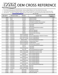
1. Recirculation Port: 1/2 in. NPT (See Flag 1 in Fig 1).<br />
2. Alternate Hot Port: 1/2 in. NPT (See Flag 2 in Fig 1).<br />
Maximum Working Pressure: 150 psi.<br />
Average Cv across valve operating temperature range:<br />
2.3<br />
Body Material: Nickel-plated brass/bronze construction,<br />
Teflon® coated valve body wear surface, Teflon® coated<br />
brass shuttle, EPDM O-rings, and proportional design<br />
(simultaneous control of hot and cold ports).<br />
Dimensions: See Fig. 1.<br />
CAUTION<br />
Injury Hazard.<br />
Exceeding recommended maximum mix temperature<br />
can cause burns.<br />
NOTE:<br />
If installing AMX300 Series Valve on a system using<br />
PEX, consult PEX tubing manufacturer for maximum<br />
allowable temperature ratings.<br />
C<br />
62-3112-03
AMX300 SERIES DIRECTCONNECT MIXING VALVE<br />
30º<br />
7/8-14 UNF-2A<br />
1-13/16<br />
(46)<br />
Ø1-1/2<br />
(38)<br />
1.500<br />
3/4-14 NPT<br />
2<br />
1-5/32<br />
(29)<br />
3-15/32<br />
(89)<br />
1<br />
2<br />
(50)<br />
4-7/32<br />
(107)<br />
1 RECIRCULATION PORT: 1/2 IN. NPT<br />
1-3/32<br />
(28)<br />
3<br />
1-3/8<br />
(34)<br />
2 ALTERNATE HOT PORT: 1/2 IN. NPT<br />
3 HOT INLET CONNECTION: 3/4-14 NPT<br />
Fig. 1. AM300 Mixing Valve dimensions in in. (mm).<br />
M31030<br />
INSTALLATION<br />
NOTE TO INSTALLER: This product should be installed by a<br />
qualified individual, in accordance with local codes and<br />
ordinances. It is the responsibility of the installer to properly<br />
select, install and adjust these devices as specified in these<br />
instructions.<br />
CAUTION<br />
Injury Hazard.<br />
Exceeding recommended maximum mix<br />
temperature can cause burns.<br />
Temperature of mixed water from the AMX300 Series<br />
DirectConnect Mixing Valve outlet should not exceed<br />
120° F (49° C).<br />
IMPORTANT<br />
1. Do NOT expose the mixing valve to temperatures<br />
below 32° F (0° C) or allow it to freeze.<br />
2. Do NOT subject the mixing valve to excess heat<br />
during installation.<br />
3. Do NOT use excess thread sealant. if sealant<br />
inadvertently enters into the mixing valve chamber, it<br />
may cause the internal assembly to malfunction.<br />
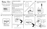
1. Before adjusting the outlet mixed water temperature,<br />
make sure that the AMX300 Valve is properly installed<br />
on the 3/4 in. hot water nipple of the water heater and<br />
that the cold water supply to the AMX300 Valve is<br />
connected. To be compliant with ASSE 1017 code, a<br />
check valve on the cold water side is required.<br />
2. To adjust the outlet mixed water temperature, you must<br />
first attach the Thermostrip (included with the valve) on<br />
the outlet pipe connected to the valve. Clean the outlet<br />
pipe of the valve first and then firmly apply the Thermostrip.<br />
Flow water and adjust the mixed water outlet temperature<br />
to the desired setting range.<br />
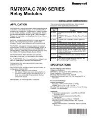
Thermostrip<br />
Accuracy expires<br />
after MMMYYYY<br />
11043<br />
11244<br />
11446<br />
11647<br />
11848<br />
12049<br />
12250<br />
Fig. 2. Thermostrip temperature indicator.<br />
NOTES:<br />
1. The Thermostrip temperature markers are colorcoded<br />
for easy reference (See Fig. 2). The actual<br />
mixed water temperature is indicated in green<br />
with 5° F (3° C) increments. Blue means slightly<br />
lower than displayed temperature, and brown<br />
means slightly higher than displayed temperature.<br />
2. The thermostrip is intended for one-time use<br />
during initial temperature setting.<br />
3. Open a hot water tap close to the water heater so that<br />
mixed water will flow through the AMX300 Valve. The<br />
Thermostrip will show the actual temperature of the<br />
mixed water within 10 seconds.<br />
4. To decrease or increase the outlet water temperature,<br />
push the mixing valve's handle in towards the valve and<br />
turn it clockwise or counterclockwise until the desired<br />
temperature is displayed on the Thermostrip.<br />
5. Ensure that the handwheel is in the locked-out position<br />
when finishing the temperature adjustment.<br />
12451<br />
WARNING<br />
Do not operate the valve at temperatures outside<br />
its calibrated range.<br />
12652<br />
12853<br />
13054<br />
13255<br />
13456<br />
13657<br />
13858<br />
14060<br />
ºF ºc<br />
M29725<br />
62-3112—03 2
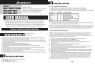
AMX300 SERIES DIRECTCONNECT MIXING VALVE<br />
Typical <strong>Installation</strong> Diagrams<br />
AMX<br />
SERIES<br />
VALVE<br />
M<br />
R H<br />
C<br />
COLD<br />
WATER<br />
HEATER<br />
(1)<br />
IN<br />
COLD<br />
WATER<br />
TEE<br />
OUT<br />
EXPANSION<br />
TANK<br />
8<br />
(203)<br />
MIN<br />
ALLOWABLE<br />
SERVICE<br />
VALVE<br />
LOCATION<br />
Fig. 3. Water heater without recirculation.<br />
COLD<br />
WATER<br />
SUPPLY<br />
V<br />
M31031<br />
The AMX300 Mixing Valve allows easy recirculation<br />
connection through the integrated recirculation port. A<br />
temperature-controlled circulating pump is required to move<br />
the tempered water through the recirculation loop. The<br />
Honeywell L6006C1018 Aquastat® Controller is the<br />
recommended temperature control device for the circulator.<br />
The Honeywell Aquastat Controller should be set 5° to 10° F<br />
(3° to 5° C) below the controlled mixed water outlet<br />
temperature.<br />
CAUTION<br />
Injury Hazard.<br />
Exceeding recommended maximum outlet mixed<br />
water temperature can cause burns.<br />
The AMX300 Series DirectConnect Mixing Valve outlet mixed<br />
water temperature should not exceed 120° F (49° C).<br />
VALVE MAINTENANCE<br />
T<br />
PUMP<br />
(1)<br />
COLD<br />
AMX<br />
SERIES<br />
VALVE M<br />
R C<br />
H<br />
WATER<br />
HEATER<br />
(1)<br />
IN<br />
COLD<br />
WATER<br />
TEE<br />
OUT<br />
8<br />
(203)<br />
MIN<br />
ALLOWABLE<br />
SERVICE<br />
VALVE<br />
LOCATION<br />
COLD<br />
WATER<br />
SUPPLY<br />
V<br />
Hard water conditions may result in scale deposits causing<br />
binding of internal parts in extreme cases. Cleaning the<br />
internal parts will usually restore the valve operating<br />
conditions. In some cases, it may be necessary to replace the<br />
lower assembly. (See Fig 5.) A Thermostatic Element<br />
Replacement Kit, AM-1-025RP, is provided by Honeywell.<br />
To clean or replace the lower assembly, shut off the water<br />
supply and:<br />
1. With a screwdriver, remove the screw and the handwheel.<br />
2. Unscrew the lower nut (turn it counterclockwise) to<br />
remove the top assembly. The brass top assembly will<br />
pop up.<br />
3. Remove the lower assembly, diffuser, and spring.<br />
EXPANSION<br />
TANK<br />
Fig. 4. Water heater with recirculation<br />
M31032<br />
Legend:<br />
1 = Check Valve.<br />
V = Any device that turns the domestic water system into a<br />
closed system, such as a backflow preventer, a check valve or<br />
a pressure reducing valve.<br />
T = Recirculation pump thermostat control.<br />
NOTE: Installing a device to function as “V” in Fig. 4 is<br />
optional and depends on local codes. If a V type<br />
valve is used, it is mandatory that a thermal expansion<br />
tank be installed as shown, otherwise, dangerously<br />
high pressures could result or the water heater<br />
safety relief valve will frequently expel water. If no V<br />
device is used, a thermal expansion tank is not<br />
required.<br />
Recirculation Loop<br />
The purpose of a recirculation loop is to supply immediate<br />
tempered water to all hot water fixtures. This helps conserve<br />
water. In the recirculation loop, the hot water supply returns<br />
from the fixture furthest from the heating source and is<br />
connected to the AMX300 Mixing Valve recirculation port<br />
(marked "R" on the valve body) and the cold supply line of the<br />
water heater.<br />
WARNING<br />
Do not use solvents or scratch the metallic or<br />
Teflon® coated surfaces.<br />
4. Carefully remove any scaling (calcium deposits) or<br />
foreign particles from the valve seat and other internal<br />
parts. Use vinegar to remove the calcium deposits.<br />
Soak parts until the calcium deposits become soft<br />
enough to be scrubbed and washed off.<br />
5. Replace the clean spring, diffuser and lower assembly<br />
following the instructions below or use a new replacement<br />
kit assembly.<br />
a. Insert the spring into the diffuser.<br />
b. Insert the diffuser with the spring end first into the<br />
body.<br />
c. Fit the valve top assembly into the lower assembly<br />
and insert into the valve.<br />
d. Tighten the lower nut.<br />
e. Tighten the upper nut.<br />
6. Place the handwheel on the valve.<br />
7. Screw the handwheel onto the valve.<br />
8. Push down and turn the handwheel to set the desired<br />
temperature.<br />
NOTE:<br />
Additional thermostrips are available from Honeywell<br />
in packs of 10 (TS205-064).<br />
3 62-3112—03
AMX300 SERIES DIRECTCONNECT MIXING VALVE<br />
FLAT SHOULDER SCREW<br />
SPRING<br />
SPINDLE ASSY<br />
O-RING<br />
DIFFUSER<br />
VALVE BODY<br />
HANDWHEEL<br />
PLASTIC SPOOL<br />
THERMAL ELEMENT<br />
SPRING, AQUAMIX-1<br />
PLUG<br />
Fig. 5. Expanded view of the AMX300 Series Mixing Valve.<br />
M31029A<br />
PRESSURE DROP (PSI)<br />
38.0<br />
36.0<br />
34.0<br />
32.0<br />
30.0<br />
28.0<br />
26.0<br />
24.0<br />
22.0<br />
20.0<br />
18.0<br />
16.0<br />
14.0<br />
12.0<br />
10.0<br />
8.0<br />
6.0<br />
4.0<br />
2.0<br />
0.0<br />
AMX3 PRESSURE DROP CHART<br />
5 6 7 8 9 10 11 12 13 14 15 16<br />
FLOW (GPM)<br />
M31033<br />
Fig. 6. Pressure Drop Chart<br />
Allen® is a registered trademark of Industrial Fasteners, Inc.<br />
Teflon is a registered trademark of E I duPont de Nemours and Company<br />
Automation and Control Solutions<br />
Honeywell International Inc. Honeywell Limited-Honeywell Limitée<br />
1985 Douglas Drive North 35 Dynamic Drive<br />
Golden Valley, MN 55422 Toronto, Ontario M1V 4Z9<br />
customer.honeywell.com<br />
® U.S. Registered Trademark<br />
© 2009 Honeywell International Inc.<br />
62-3112—03 K.K. Rev. 09-09