U5B-Z3 High Performance Water Pressure Reducing Valve
U5B-Z3 High Performance Water Pressure Reducing Valve
U5B-Z3 High Performance Water Pressure Reducing Valve

Create successful ePaper yourself
Turn your PDF publications into a flip-book with our unique Google optimized e-Paper software.
For Residential and Commercial Applications<br />
ES-<strong>U5B</strong><br />
Job Name ––––––––––––––––––––––––––––––––––––––––––– Contractor ––––––––––––––––––––––––––––––––––––––––––––<br />
Job Location ––––––––––––––––––––––––––––––––––––––––– Approval –––––––––––––––––––––––––––––––––––––––––––––<br />
Engineer ––––––––––––––––––––––––––––––––––––––––––––– Contractor’s P.O. No. –––––––––––––––––––––––––––––––––––<br />
Approval ––––––––––––––––––––––––––––––––––––––––––––– Representative ––––––––––––––––––––––––––––––––––––––––<br />
Series <strong>U5B</strong><br />
<strong>Water</strong> <strong>Pressure</strong> <strong>Reducing</strong> <strong>Valve</strong>s*<br />
Sizes: 1 ⁄2" – 2" (15 – 50mm)<br />
Series <strong>U5B</strong> <strong>Water</strong> <strong>Pressure</strong> <strong>Reducing</strong> <strong>Valve</strong>s are designed to reduce incoming<br />
water pressure to a sensible level to protect plumbing system components<br />
and reduce water consumption. This series is suitable for<br />
water supply pressures up to 300psi (20.7 bar) and may be adjusted from<br />
25 – 75psi (172 – 517 kPa). The standard setting is 50psi (345 kPa). All<br />
parts are quickly and easily serviceable without removing the valve from the<br />
line. The <strong>U5B</strong>’s standard bypass feature permits the flow of water back<br />
through the valve into the main when pressures, due to thermal expansion<br />
on the outlet side of the valve, exceed the pressure in the main.<br />
Features<br />
• Standard construction includes <strong>Z3</strong> sealed spring cage and corrosion<br />
resistant adjusting cage screws for accessable outdoor or pit installations<br />
• Integral stainless steel strainer<br />
• Replaceable seat module<br />
• Bronze body construction<br />
• Serviceable in line<br />
• Bypass feature controls thermal expansion pressure (<strong>U5B</strong>-<strong>Z3</strong>)**<br />
• <strong>High</strong> temperature resistant reinforced diaphragm for hot water<br />
Models<br />
<strong>U5B</strong>-<strong>Z3</strong><br />
<strong>U5B</strong>-S-<strong>Z3</strong><br />
5M3-Z6<br />
<strong>U5B</strong>-QC-<strong>Z3</strong><br />
Specifications<br />
NPT threaded female union inlet x NPT female outlet w/built in<br />
thermal expansion bypass<br />
Solder union inlet x NPT female outlet w/built in thermal<br />
expansion bypass<br />
<strong>Water</strong> meter threaded connections and 7 1 ⁄2" (190mm) lay<br />
length for new or existing meter box installations. For 5 ⁄8"<br />
(16mm), 5 ⁄8" x 3 ⁄4" (16 x 20mm) or 3 ⁄4" (20mm) meter<br />
setters or resetters<br />
Quick-Connect Single-Union – Inlet end<br />
Standard Specifications: A <strong>Water</strong> <strong>Pressure</strong> <strong>Reducing</strong> <strong>Valve</strong> with integral<br />
strainer shall be installed in the water service pipe near its entrance to the<br />
building where supply main pressure exceeds 60psi (413 kPa) to reduce it<br />
to 50psi (345 kPa) or lower. The valve shall feature a bronze body suitable<br />
for water supply pressures up to 300psi (20.7 bar). Provision shall be made<br />
to permit the bypass flow of water around the valve back into the main<br />
when pressures, due to thermal expansion on the outlet side of the valve,<br />
exceed the pressure in the main. <strong>Water</strong> <strong>Pressure</strong> <strong>Reducing</strong> <strong>Valve</strong> with builtin<br />
bypass check valves will be acceptable. Approved valve shall be listed to<br />
ASSE 1003 and IAPMO and certified to CSA B356. <strong>Valve</strong> shall be a Watts<br />
Regulator Company Series <strong>U5B</strong>-<strong>Z3</strong>.<br />
* A water saving test program concluded that reducing the supply pressure<br />
from 80-50psi (551-345 kPa) resulted in a water savings of 30%.<br />
** Bypass will not work if inlet pressure is above 150psi (10.3 bar).<br />
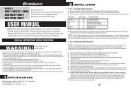
<strong>U5B</strong>-<strong>Z3</strong><br />
Sensitive spring and large diaphragm<br />
area provide for accurate pressure<br />
control and wide range of adjustment.<br />
<strong>High</strong> temperature resisting<br />
diaphragm for hot or cold water.<br />
Suffix B Bypass feature<br />
Large integral<br />
stainless steel<br />
strainer screen<br />
easily removed<br />
for cleaning.<br />
Stainless steel seat<br />
Suffix B<br />
Thermal Expansion Bypass Check <strong>Valve</strong> Feature<br />
Expanded<br />
<strong>Pressure</strong><br />
Initial<br />
<strong>Pressure</strong><br />
Bronze body construction<br />
Reduced<br />
<strong>Pressure</strong><br />
Disc holder removable<br />
for replacement of disc<br />
without dismantling<br />
the valve - no special<br />
tools required.<br />
Spring (not shown)<br />
“LP” Model only<br />
Inlet Seat and Disc<br />
Watts product specifications in U.S. customary units and metric are approximate and are provided for reference only. For precise measurements,<br />
please contact Watts Technical Service. Watts reserves the right to change or modify product design, construction, specifications, or materials<br />
without prior notice and without incurring any obligation to make such changes and modifications on Watts products previously or subsequently sold.
Materials<br />
Body:<br />
Seat:<br />
Integral Strainer:<br />
Diaphragm:<br />
<strong>Valve</strong> Disc:<br />
Bronze<br />
Replaceable stainless steel<br />
Stainless steel<br />
Reinforced EPDM<br />
EPDM<br />
Note: for LP models where application temperatures exceed 160°F (71°C),<br />
but not over 180°F (82°C), a Teflon ® protector should be added to<br />
sizes 1 1 ⁄4" – 2" (32 – 50mm).<br />
5M3-Z6 model provided with cast iron spring cage<br />
<strong>Pressure</strong> – Temperature<br />
Temperature Range: 33°F – 160°F (0.5°C – 71°C)<br />
Maximum Working <strong>Pressure</strong>: 300psi (20.7 bar)<br />
Adjustable Reduced <strong>Pressure</strong> Range: 25 – 75psi (172 – 517 kPa)<br />
Standard Reduced <strong>Pressure</strong> Setting: 50psi (345 kPa)<br />
Options<br />
Add Suffix<br />
G Gauge tapping<br />
GG Gauge tapping and 160psi (11 bar) gauge<br />
HP <strong>High</strong> pressure range 75 – 100psi (5.2 – 6.9 bar)<br />
LP Low pressure range 10 – 35psi (69 – 241 kPa)<br />
Standards<br />
Meets requirements of ASSE Standard 1003; (ANSI A112.26.2); CSA<br />
Standard B356; Southern Standard Plumbing Code and listed by IAPMO.<br />
Teflon® is a registered trademark of E.I. Dupont de Nemours & Company.<br />
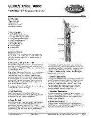
Capacity<br />
Reduced <strong>Pressure</strong> Fall-off<br />
Reduced <strong>Pressure</strong> Fall-off<br />
kPa psi<br />
172 25<br />
138 20<br />
103 15<br />
69 10<br />
34 5<br />
0 0<br />
0 10 20 30 40 50 gpm<br />
0 38 76 114 152 190 lpm<br />
kPa psi<br />
172 25<br />
138 20<br />
103 15<br />
69 10<br />
34 5<br />
0 0<br />
Sizes 1 ⁄2", 3 ⁄4", 1" (15, 20, 25mm)<br />
1<br />
⁄2" 3<br />
⁄4" 1"<br />
Sizes 1 1 ⁄4", 1 1 ⁄2", 2" (32, 40, 50mm)<br />
1 1 ⁄4"<br />
1 1 ⁄2"<br />
10 30 50 70 90 110 gpm<br />
38 114 190 266 342 418 lpm<br />
2"<br />
Dimensions - Weights<br />
Et<br />
A - <strong>U5B</strong>-<strong>Z3</strong><br />
A1 - <strong>U5B</strong>-S-<strong>Z3</strong><br />
ET - NPT Engagement for tight joint<br />
ES - Female sweat socket depth<br />
EQC- Quick-Connect<br />
F* (Max)<br />
G<br />
Es<br />
FQC<br />
D<br />
C (Max)<br />
EQC<br />
A1<br />
A<br />
MODEL SIZE (DN) DIMENSIONS WEIGHT<br />
A A1 C D G Et Es EQC FQC F *<br />
in. mm in. mm in. mm in. mm in. mm in. mm in. mm in. mm in. mm in. mm in. mm lbs. kgs.<br />
<strong>U5B</strong>-<strong>Z3</strong> 1<br />
⁄2 15 5 5 ⁄8 142.8 5 1 ⁄2 139.7 5 7 ⁄8 149.2 1 5 ⁄8 41.2 3 1 ⁄16 77.7 7<br />
⁄16 11.1 1<br />
⁄2 12.7 1 7 ⁄16 36 1 1 ⁄2 38 10 1 ⁄4 260.3 4 1.8<br />
3<br />
⁄4 20 6 3 ⁄16 157.1 6 1 ⁄4 158.7 6 7 ⁄8 174.6 1 7 ⁄8 47.6 3 1 ⁄2 88.9 1<br />
⁄2 12.7 3<br />
⁄4 19 1 9 ⁄16 40 1 11 ⁄16 42 11 1 ⁄2 292.1 5 2.3<br />
1 25 6 5 ⁄8 168.2 6 3 ⁄4 171.4 7 3 ⁄8 187.3 2 50.8 4 101.6 9 ⁄16 14.2 7<br />
⁄8 22.2 1 11 ⁄16 43 1 3 ⁄4 45 12 1 ⁄8 307.9 6 2.7<br />
1 1 ⁄4 32 7 15 ⁄16 190.5 7 11 ⁄16 195.2 8 3 ⁄8 212.7 2 1 ⁄4 57.1 4 1 ⁄2 113.3 5<br />
⁄8 15.8 1 25.4 13 3 ⁄8 339.7 9.4 4.3<br />
1 1 ⁄2 40 9 7 ⁄16 239.7 9 3 ⁄4 247.6 9 3 ⁄8 238.1 2 7 ⁄8 73 4 3 ⁄4 120.6 5<br />
⁄8 15.8 1 1 ⁄8 28.5 15 381.0 14.4 6.5<br />
2 50 10 7 ⁄8 276.2 11 1 ⁄2 292.1 12 1 ⁄4 311.1 3 1 ⁄4 82.5 6 152.4 5<br />
⁄8 15.8 1 3 ⁄8 34.9 18 1 ⁄4 463.5 23 10.4<br />
* Dimension includes optional gauge<br />
<strong>Water</strong> Safety & Flow Control Products<br />
USA: 815 Chestnut St., No. Andover, MA 01845-6098; www.watts.com<br />
Canada: 5435 North Service Rd., Burlington, ONT. L7L 5H7; www.wattscanada.ca<br />
ES-<strong>U5B</strong> 0821 © Watts, 2008