Installation Manual - Jackson Systems
Installation Manual - Jackson Systems
Installation Manual - Jackson Systems

You also want an ePaper? Increase the reach of your titles
YUMPU automatically turns print PDFs into web optimized ePapers that Google loves.
1<br />
Specifications<br />
cont.<br />
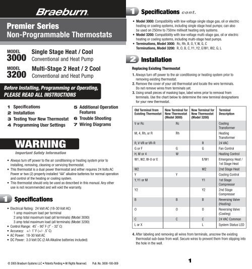
Premier Series<br />
Non-Programmable Thermostats<br />
MODEL<br />
3000<br />
MODEL<br />
3200<br />
1<br />
2<br />
3<br />
4<br />
Specifications<br />
<strong>Installation</strong><br />
Testing Your New Thermostat<br />
Programming User Settings<br />
WARNING<br />
Important Safety Information<br />
1 Specifications<br />
Single Stage Heat / Cool<br />
Conventional and Heat Pump<br />
Multi-Stage 2 Heat / 2 Cool<br />
Conventional and Heat Pump<br />
Before Installing, Programming or Operating,<br />
PLEASE READ ALL INSTRUCTIONS<br />
• Electrical Rating: 24 Volt AC (18-30 Volt AC)<br />
1 amp maximum load per terminal<br />
2 amp total maximum load (all terminals) (Model 3000)<br />
3 amp total maximum load (all terminals) (Model 3200)<br />
• Control Range: 45˚ - 90˚ F (7˚ - 32˚ C)<br />
• Accuracy: +/- 1˚ F (+/- .5˚ C)<br />
• AC Power: 18-30 Volt AC<br />
• DC Power: 3.0 Volt DC (2 AA Alkaline batteries included)<br />
5<br />
6<br />
7<br />
Additional Operation<br />
Features<br />
Trouble Shooting<br />
Wiring Diagrams<br />
• Always turn off power to the air conditioning or heating system prior to<br />
installing, removing, cleaning or servicing thermostat.<br />
• This thermostat is a dual power thermostat and either requires 24 Volts AC<br />
Power or two (2) properly installed “AA” alkaline batteries for normal operation<br />
and control of the heating or cooling system.<br />
• This thermostat should only be used as described in this manual. Any other<br />
use is not recommended and will void the warranty.<br />
• Model 3000: Compatibility with low voltage single stage gas, oil or electric<br />
heating or cooling systems, including single stage heat pumps; can also<br />
be used on 250mv to 750mv millivolt heating only systems.<br />
• Model 3200: Compatibility with low voltage multi-stage gas, oil or electric<br />
heating or cooling systems, including multi-stage heat pumps.<br />
• Terminations, Model 3000: Rc, Rh, B, O, Y, W, G, C<br />
Terminations, Model 3200: R, O, B, C, Y1, Y2, E/W1, W2, G, L<br />
2<br />
<strong>Installation</strong><br />
Replacing Existing Thermostat<br />
1. Always turn off power to the air conditioning or heating system prior to<br />
removing existing thermostat.<br />
2. Remove the cover of your old thermostat and locate the wire terminals.<br />
Do not remove wires from terminals yet.<br />
3. Using small pieces of masking tape, label wires prior to removal from<br />
terminals. Use the chart below to determine the new terminal designations<br />
for your new thermostat.<br />
Old Terminal from<br />
Existing Thermostat<br />
New Terminal for<br />
New Thermostat<br />
(Model 3000)<br />
New Terminal for<br />
New Thermostat<br />
(Model 3200)<br />
Terminal<br />
Description<br />
V or Rc Rc Cooling<br />
Transformer<br />
M, 4, Rh, or R Rh Heating<br />
Transformer<br />
R, V-VR or VR-R R 24 VAC<br />
G or F G G Fan Control<br />
H, W or 4 W Heating Control<br />
W1, W2, W-U or E E/W1 Emergency Heat /<br />
1st Stage Heat<br />
W2 W2 2nd Stage Heat<br />
Y Y Cooling Control<br />
Y, Y1 or M Y1 1st Stage<br />
Compressor<br />
Y2 Y2 2nd Stage<br />
Compressor<br />
B B B Reversing Valve<br />
(Heating)<br />
O O O Reversing Valve<br />
(Cooling)<br />
C C C 24 VAC Common<br />
L or X L System Status LED<br />
4. After labeling and removing all wires from terminals, unscrew the existing<br />
thermostat sub-base from wall. Secure wires to prevent them from slipping into<br />
the hole in the wall.<br />
© 2005 Braeburn <strong>Systems</strong> LLC • Patents Pending • All Rights Reserved. Pub. No. 3000-100-009<br />
1
2 <strong>Installation</strong> cont.<br />
NOTE–MODEL 3000: This thermostat is designed for use with 24 Volt-AC low<br />
voltage single stage gas, oil or electric heating or cooling systems, including<br />
single stage heat pumps and can also be used on 250mv to 750mv millivolt<br />
heating only systems. Do not use this thermostat on applications with voltages<br />
above 30 Volts AC.<br />
NOTE–MODEL 3200: This thermostat is designed for use with 24 Volt-AC low<br />
voltage multi-stage gas, oil or electric heating or cooling systems, including<br />
multi-stage heat pump systems. Do not use this thermostat on applications with<br />
voltages above 30 Volts AC.<br />
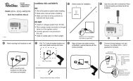
Installing Your New Thermostat<br />
NOTE: If installing this thermostat in a new installation, locate the thermostat 4<br />
to 5 feet above the floor in accordance with applicable building codes. Install the<br />
thermostat in a location that provides good airflow characteristics and avoid areas<br />
behind doors, near corners, air vents, direct sunlight or heat generating devices.<br />
<strong>Installation</strong> in these areas could impact thermostat performance. Wiring must<br />
conform to all building codes and ordinances as required by local and national<br />
code authorities having jurisdiction.<br />
1. Turn off power to the air conditioning or heating system prior to installing thermostat.<br />
2. Place system switch on front of thermostat to OFF position.<br />
3. Place fan control switch on front of thermostat to AUTO position.<br />
4. Remove front of thermostat body from sub-base by pressing release latch.<br />
5. Place the thermostat sub-base against wall in the desired thermostat location.<br />
6. Guide thermostat wires through hole in sub-base. Continue to hold against wall.<br />
7. Mark placement of mounting holes and drill using a 3/16" drill bit.<br />
8. Gently tap supplied plastic anchors into the holes in the wall.<br />
9. Place the thermostat sub-base against the wall in the desired location, making<br />
sure the mounting holes are aligned and the thermostat wires are inserted<br />
through opening in sub-base.<br />
10. Fasten sub-base to wall using supplied screws into the plastic wall anchors.<br />
11. Connect wires to quick wiring terminal block as appropriate using the new<br />
terminal designations. See Section 7.<br />
12. Make sure all of the wire connections are secure and are not touching any other<br />
terminal to prevent electrical shorts and potential damage to the thermostat.<br />
13. Turn the front thermostat body over, exposing the rear view of the circuit board.<br />
14. Locate the internal ˚F / ˚C switch on the circuit board. Using your fingers, flip<br />
the switch toward the preferred temperature ˚F / ˚C scale.<br />
15. Locate the internal fan option switch, HG (Gas) / HE (Elec) on the circuit board.<br />
This switch controls the heating system fan delay. Select gas for gas or oil fired<br />
systems. This will allow the furnace to run for a few seconds before initiating<br />
the fan. Select electric for systems with electric furnace elements that require<br />
the fan to come on immediately. Using your finger, flip the switch toward the<br />
HG (Gas) or HE (Elec).<br />
16. Locate the internal NORM / HP switch on the circuit board. This switch<br />
configures the thermostat for conventional (NORM) heating and cooling systems<br />
or heat pump (HP) systems. Using your fingers, flip the switch toward the<br />
NORM or HP.<br />
17. MODEL 3200 ONLY: Locate the auxiliary heat option switch, AE-AG, on the<br />
circuit board. For electric auxiliary heat units, the switch should be set to the<br />
AE position. For units with gas or oil auxiliary heat, move the switch to the AG<br />
position. This will lock out the compressor stage 1 minute after a second stage<br />
heat call for maximum efficiency.<br />
2 <strong>Installation</strong> cont.<br />
18. Attach front body of thermostat to sub-base of thermostat, being careful<br />
to align the terminal pins on the front body with the terminal block on<br />
the sub-base.<br />
19. Open front thermostat door and open battery compartment door.<br />
20. Install two new "AA" alkaline batteries. Locate the positive (+) ends of the<br />
batteries and match them with the positive (+) terminals located in the battery<br />
compartment. Close battery compartment.<br />
21. Restore system power so you can test installation.<br />
NOTE: If batteries were installed prior to accomplishing steps 14 through 16,<br />
you will need to reset the thermostat to register thermostat switch configurations<br />
prior to programming any user settings. Gently press the RESET button on the<br />
front of the thermostat using a paper clip or a small pencil tip.<br />
NOTE–MODEL 3200: If the thermostat is<br />
configured for a conventional system and the<br />
system switch is in the EM HEAT position, the<br />
unit will still function in a conventional 2 stage<br />
HEAT mode, but the display will flash<br />
NO EM HEAT SET.<br />
Testing Your New Thermostat<br />
WARNING! Read BEFORE Testing<br />
2 3<br />
3<br />
• Do not short (or jumper) across terminals on the gas valve or at the heating or<br />
cooling system control board to test the thermostat installation. This could<br />
damage the thermostat and void the warranty.<br />
• Do not select COOL mode if the outside temperature is below 50˚ F (10˚ C). This<br />
could damage the controlled cooling system and may cause personal injury.<br />
• This thermostat includes an automatic compressor protection feature to avoid<br />
potential damage to the cooling system from short cycling. This thermostat<br />
automatically provides a 5-minute delay after turning off the cooling or heating<br />
system output to protect the compressor.<br />
NOTE: Test your thermostat prior to programming any user settings. Pressing the<br />
RESET button will erase any user entries previously programmed and return them<br />
to their default values.<br />
1. Place the system switch in the HEAT position.<br />
2. Press the button on the keypad until the set point temperature setting is a<br />
minimum of 3 degrees higher than the current room temperature. The heating<br />
system should start within several seconds. The fan may not turn on immediately<br />
due to the heating system built-in fan delay.<br />
3. Place the system switch in the OFF position. The heating system should stop<br />
within several seconds on conventional heating or cooling systems. On heat<br />
pump systems, you must wait 5 minutes for the automatic compressor short<br />
cycle protection period to expire, or press the RESET button to bypass this<br />
feature for initial testing purposes. Pressing the RESET button will erase any<br />
user program settings.<br />
4. Place the system switch in the COOL position.<br />
5. Press the button on the keypad until the set point temperature is a minimum<br />
of 3 degrees lower than the current room temperature.
3<br />
Testing Your New Thermostat<br />
cont.<br />
4<br />
Programming User Settings<br />
cont.<br />
6. The cooling system should start within several seconds. Place the system switch<br />
in the OFF position. The cooling system should stop within a few seconds.<br />
7. Place the fan switch in the ON position. The system blower should start.<br />
8. Place the fan switch in the AUTO position. The system blower should stop.<br />
4<br />
Programming User Settings<br />
Default Thermostat Settings<br />
Function<br />
Operation Mode<br />
Room Temperature<br />
Set Point Temperature<br />
Temperature Scale<br />
Low Battery Warning<br />
1st Stage Differential<br />
2nd Stage Differential<br />
Short Cycle Protection Timer<br />
Output Relays<br />
Residual Cooling Fan Delay<br />
Recirculating Fan Timer<br />
Keypad Lock<br />
Setting Temperature Differentials<br />
Status After Reset<br />
Normal Operating Mode<br />
70˚ F (21.0˚ C), to be<br />
renewed within 5 seconds<br />
According to system switch<br />
Heat or Off: 62˚ F (17.0˚ C)<br />
Emergency Heat (model 3200 only):<br />
62˚ F (17.0˚ C)<br />
Cool: 85˚ F (29.0˚ C)<br />
˚F or ˚C dependent on switch setting<br />
Off, to be renewed within 5 seconds<br />
Off if 24V is present<br />
0.5˚ F (0.3˚C)<br />
2˚ F (1.0˚ C) (model 3200 only)<br />
Reset<br />
Off<br />
60 Seconds<br />
Reset with 120 Min. Off Cycle<br />
Unlocked<br />
The default settings for the first and second stage differentials are compatible<br />
with most systems and applications. This is normally set at time of installation and<br />
usually does not require any modification under normal operating conditions. If you<br />
feel that your system is turning on too often, simply follow the instructions below.<br />
NOTE: The temperature differential settings are the same for both the heating<br />
and cooling systems.<br />
Setting First Stage Differential<br />
The default setting is 0.5˚ F (0.25˚ C). The room temperature must change .5˚ F<br />
(0.25˚ C) from the set point temperature before the thermostat will initiate the<br />
system in heating or cooling.<br />
1. In normal operating mode, press and hold<br />
the and buttons at the same time for 3<br />
seconds. LCD display will show "SET D1 X˚",<br />
where "X" equals the ˚F / ˚C differential setting.<br />
This is the current first stage differential setting.<br />
2. Press the or buttons to set the first stage differential to your desired<br />
setting of .5˚, 1˚, or 2˚ F (.25––displayed as .3˚, .5˚ or 1˚ C).<br />
Setting First Stage Differential (continued from page 4)<br />
3. Press both the and buttons at the same time again to change the next<br />
setting. For the model 3200, the next setting is the Second Stage Differential.<br />
For the model 3000, the next setting is the Residual Cooling Fan Delay, or wait<br />
5 seconds for the thermostat to return to the normal operating mode.<br />
Setting Second Stage Differential (Model 3200 Only)<br />
The default setting is 2˚ F (1.0˚ C). The room temperature must change 2˚ F<br />
(1.0˚ C) in addition to the first stage differential setting before the thermostat will<br />
initiate the second stage of the system in heating.<br />
4. Press and hold the and buttons at the same<br />
time again and the LCD display will show "SET<br />
D2 X˚", where "X" equals the ˚F / ˚C differential<br />
setting. This is the current second stage<br />
differential setting.<br />
5. Press the or buttons to set the second stage differential to your desired<br />
setting of 2˚, 3˚, 4˚, 5˚or 6˚ F (1˚, 1.5˚, 2˚, 2.5˚ or 3˚ C).<br />
6. Press and hold the and buttons at the same time to change the residual<br />
cooling fan delay, or wait 5 seconds for the thermostat to return to the<br />
normal operating mode.<br />
Setting Residual Cooling Fan Delay<br />
The default setting is 60 seconds. During the COOL mode of operation, the fan<br />
will stay on for 60 seconds after the cooling system has reached the set point<br />
temperature and has turned off the compressor. This improves system efficiency<br />
during cooling operation.<br />
1. The display will show "FAN SET XX", where<br />
"XX" is the fan delay time in seconds.<br />
2. Press the or button to change the Residual<br />
Cooling Fan Delay (0, 30, 60, or 90 seconds).<br />
3. Press both the and buttons at the same time again to change the<br />
Recirculating Fan cycle, or wait 5 seconds for the thermostat to return to the<br />
normal operating mode.<br />
Setting the Recirculating Fan Cycle (also see section 5)<br />
The default is 24 minutes.<br />
1. The display will show "FAN OC SET XX",<br />
where "XX" is the maximum interval of time<br />
(in minutes) that the fan will remain off if the<br />
Recirculating Fan Mode is selected.<br />
2. Press the or button to change the<br />
Recirculating Fan off cycle (60, 40 or 24 minutes).<br />
3. Press both the and buttons at the same time again to return to the normal<br />
operating mode, or wait 5 seconds for the thermostat to return to the normal<br />
mode automatically.<br />
NOTE: To erase all user program settings, gently press the RESET button using a<br />
paper clip or a small pencil tip. This will return all thermostat settings to their<br />
default values, erasing all program settings entered by the user.<br />
4 5
5<br />
Additional Operation Features<br />
Review Set Temperature<br />
1. Press and hold the or button. The current<br />
set point temperature will be displayed in place<br />
of the current room temperature, and the<br />
indicator SET will be displayed.<br />
2. The display will return to normal operating mode<br />
when the or button is released. The SET indicator will turn off, indicating<br />
that the current temperature shown in the display is the room temperature.<br />
Changing Set Temperature<br />
1. Press and hold or button for more than 1<br />
second. The entire display will flash once and<br />
the SET indicator will be flashing. Release the<br />
or button and press the or button again<br />
to adjust the set temperature.<br />
2. The display will return to normal operating mode after 5 seconds, or you<br />
can press both the and buttons at the same time to return to normal<br />
operating mode.<br />
3. The SET indicator will turn off in the display, indicating that the current<br />
temperature shown in the display is the room temperature.<br />
NOTE: Select either COOL or HEAT with the system switch to view or change<br />
cooling or heating set points.<br />
Recirculating Fan Mode (see section 4)<br />
The Recirculating Fan Mode provides more even temperature distribution and<br />
improves indoor air quality by circulating air through the furnace filtration system<br />
more often. The Recirculating Fan Mode can be selected by moving the fan<br />
switch to the recirculate position . If no call for heating or cooling occurs<br />
®<br />
within the fan off cycle set in section 4, the fan will run for 12 minutes. The<br />
highest setting, 60 minutes, will run the fan least often–17% minimum run time.<br />
The lowest setting, 24 minutes (factory default), will run the fan most often–33%<br />
minimum run time. During any call for heating or cooling, fan control operates in<br />
the AUTO mode. This feature is available in the HEAT, OFF, or COOL mode.<br />
Keypad Lockout<br />
To prevent accidental or undesired adjustment of<br />
the thermostat set point, the Keypad Lockout<br />
feature disables the operation of the temperature<br />
setting keys, but not the backlight key. In order to<br />
enable the keypad lock, press and hold either the<br />
or button together with the backlight button<br />
for 5 seconds. The LOCK icon in the display will flash once per second, then<br />
appear continuously in the display. The keypad is now locked.<br />
To unlock the keypad, press and hold either the or button together with the<br />
backlight key for 1 second. The LOCK icon will disappear from the display, and<br />
the key pad is now unlocked.<br />
5 Additional Operation Features cont.<br />
Compressor Protection Feature<br />
This thermostat includes an automatic compressor protection feature to avoid<br />
potential damage to the system from short cycling. This thermostat automatically<br />
provides a 5-minute delay after turning off the cooling system output to protect<br />
the compressor. This protection is also present in the heat mode of operation on<br />
heat pump systems to protect the compressor.<br />
NOTE: The installer can bypass the compressor protection feature by pressing<br />
the RESET button. This will erase all user program settings, returning all settings<br />
to their default values. This should only be used during installation for testing<br />
purposes or to reset a thermostat to regain normal operation.<br />
Low Battery Detection and Replacement<br />
This thermostat requires two (2) properly installed<br />
"AA" alkaline batteries to provide power for the<br />
thermostat if 24 volt AC power is not connected to<br />
the terminal block. This thermostat is equipped<br />
with a unique, three level low battery detection<br />
feature that constantly monitors the batteries<br />
during normal operating mode to determine whether they have sufficient power to<br />
provide proper operation.<br />
When this feature determines that the battery status is low, a low battery indicator<br />
will appear in the display. After 30 days the battery indicator will start to flash, and<br />
after 60 days the battery indicator will begin to flash faster, indicating that the<br />
batteries need to be replaced immediately to maintain system operation and<br />
program settings.<br />
Replacing the Batteries<br />
1. Open the front cover and locate the battery compartment door.<br />
2. Remove the two "AA" alkaline batteries located in the battery compartment.<br />
3. Install two new "AA" alkaline batteries into battery compartment. Make sure<br />
to match the positive (+) ends of the batteries with the positive (+) terminals<br />
located in the battery compartment.<br />
4. Close battery compartment. The low battery indicator should not appear<br />
in the display.<br />
Non-Volatile Memory<br />
In the event of a power failure, the Non-Volatile Memory feature allows all settings<br />
to be recovered, eliminating the need to reset temperature and differential settings.<br />
When AC power is restored after an outage or batteries are reinserted, all settings<br />
are retrieved from memory and reinstated.<br />
6<br />
7
5 Additional Operation Features cont.<br />
Status Indicators (Model 3200 Only)<br />
There are three status indicators that can be displayed to notify you of key<br />
system information.<br />
AUX:<br />
This will turn on when the auxiliary<br />
second stage of heating or cooling is<br />
active. The auxiliary stage of heating is<br />
usually the least economical stage of heat.<br />
CHECK: Indicator will be displayed when a<br />
malfunction occurs in the heat pump<br />
system. When this light is active, call a<br />
professional service technician to verify<br />
system performance and switch the<br />
system to Emergency Heat mode if<br />
required to maintain room temperature.<br />
EM:<br />
6<br />
Indicator will be displayed when<br />
Emergency Heat Mode of operation is<br />
selected using the system selector<br />
switch. When selected, the heat pump<br />
stage of heat is turned off and the<br />
emergency (auxiliary) stage of heating is<br />
used to maintain the set point temperature.<br />
Troubleshooting<br />
Symptom: Thermostat does not turn on heating or cooling system.<br />
Potential Solution: Check to see if OFF is shown in display. This indicates that<br />
the system is turned off at the thermostat. Move the system selector switch to<br />
the HEAT or COOL position. After the compressor short cycle protection 5-minute<br />
period expires, the system should start.<br />
Compressor protection feature may be in effect due to compressor short cycle<br />
conditions. See Section 5.<br />
Heating or cooling system may be malfunctioning. Call a professional service<br />
technician immediately to verify system operation.<br />
Symptom: Thermostat turns on heating instead of cooling or cooling instead<br />
of heating.<br />
Potential Solution: Check thermostat wiring to make sure that the heating<br />
and cooling stages are connected to the correct terminals on the wiring terminal<br />
block. See Section 7.<br />
Symptom: Thermostat turns heating or cooling system on too often or not<br />
often enough.<br />
Potential Solution: Increase or decrease temperature differential settings as<br />
appropriate to provide the desired performance level. See Section 4.<br />
Symptom: Low battery indicator is shown in thermostat display.<br />
Potential Solution: Replace batteries immediately to maintain proper system<br />
operation. See Section 5.<br />
6<br />
Troubleshooting<br />
cont.<br />
Symptom: OFF is shown in thermostat display<br />
and heating or cooling system will not start.<br />
Potential Solution: This indicates that the system<br />
is turned off at the thermostat. The thermostat<br />
must be in HEAT or COOL modes of operation to<br />
control the heating or cooling system. Move the<br />
system selector switch to the HEAT or COOL position.<br />
Symptom: Thermostat display is blank.<br />
Potential Solution: It is possible that AC power is not present at the thermostat<br />
and/or the batteries are drained. Check fuse, circuit breaker and thermostat<br />
wiring as appropriate to verify AC power is available. Replace batteries before<br />
reprogramming thermostat. See Section 5. If AC power is present, call a<br />
professional service technician to verify thermostat and system performance.<br />
Symptom: The room is too warm or too cold.<br />
Potential Solution: See Section 5. Review current set point and change<br />
as necessary.<br />
Symptom: Fan runs intermittently or when system is off.<br />
Potential Solution: Fan switch is in Recirculate Mode .<br />
Symptom: HI is shown in the thermostat display.<br />
Potential Solution: The temperature sensed by<br />
the thermostat is higher than the 99˚ F (37˚ C)<br />
upper limit of the thermostats display range. The<br />
display will return to normal after the sensed<br />
temperature lowers within the 40˚ to 99˚ F (4˚ to<br />
37˚ C) display range. Turn on the cooling system or use other methods to lower the<br />
temperature accordingly.<br />
This condition could occur from the system being turned off during an exceptionally<br />
warm period or upon installation when the thermostat has been stored for a<br />
long period of time in a warm vehicle or location prior to being installed.<br />
Symptom: LO is shown in the thermostat display.<br />
Potential Solution: The temperature sensed by<br />
the thermostat is lower than the 40˚ F (4˚ C) lower<br />
limit of the thermostat’s display range. The display<br />
will return to normal after the sensed temperature<br />
rises within the 40˚ to 99˚ F (4˚ to 37˚ C) display<br />
range. Turn on the heating system to raise the temperature as needed for comfort<br />
within the room.<br />
This condition could occur from the system being turned off during a cold weather<br />
period or upon installation when the thermostat has been stored for a long period<br />
of time in a cold vehicle or location prior to being installed. The thermostat should<br />
be allowed to warm up prior to installation in order to provide proper heating<br />
control once installed.<br />
Symptom: Cannot program a set point temperature higher than 90˚ F (32˚ C).<br />
Potential Solution: This is above the normal thermostat temperature setting<br />
range of 45˚ to 90˚ F (7˚ to 32˚ C).<br />
®<br />
8 9
6 Troubleshooting cont.<br />
Symptom: Cannot program a set point temperature lower than 45˚ F (7˚ C).<br />
Potential Solution: This is below the normal thermostat temperature setting<br />
range of 45˚ to 90˚ F (7˚ to 32˚ C).<br />
Symptom: Thermostat will not allow me to change the set point.<br />
Potential Solution: The keypad is locked. Press either the or key and the<br />
backlight key at the same time to unlock.<br />
Symptom: Fan continues to run all the time whether the system is on or off.<br />
Potential Solution: Check to make sure the fan control switch is in the AUTO<br />
position. This will allow the fan to run only when the heating or cooling system is<br />
turned on and running.<br />
Check thermostat wiring to make sure that the fan control wiring is connected to<br />
the correct terminals on the wiring terminal block. See Section 7.<br />
Symptom: CHECK is shown in thermostat display.<br />
(model 3200 only)<br />
Potential Solution: Switch to emergency heat<br />
if heat is required. Please contact a professional<br />
service technician to verify thermostat and<br />
system performance.<br />
Symptom: NO EM HEAT SET is shown in the<br />
thermostat display. (model 3200 only)<br />
Potential Solution: The thermostat (model 3200<br />
only) is configured for a conventional system,<br />
and the system switch is in the EM HEAT position.<br />
The unit will still function in a conventional 2<br />
stage HEAT mode, but the display will flash NO<br />
EM HEAT SET. Move the system switch to the HEAT position.<br />
7<br />
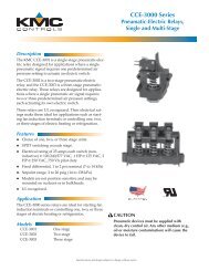
Wiring Diagrams<br />
MODEL 3000: Conventional <strong>Systems</strong> (Single Transformer)<br />
Factory Installed<br />
Jumper<br />
Rc Rh B O Y<br />
Cool<br />
Control<br />
W<br />
Heat<br />
Control<br />
G<br />
Fan<br />
Control<br />
C<br />
Transformer Common<br />
(See NOTE 1)<br />
7<br />
Wiring Diagrams<br />
MODEL 3000: Conventional <strong>Systems</strong> (Dual Transformer)<br />
Remove<br />
Factory Installed<br />
Jumper<br />
Hot Side<br />
Cool<br />
Transformer<br />
Factory Installed<br />
Jumper<br />
Rc<br />
Hot Side<br />
Heat<br />
Transformer<br />
Rc<br />
Rh<br />
Heat 24 VAC<br />
Transformer<br />
120<br />
Volt AC<br />
Rh<br />
Cool<br />
Control<br />
Heat<br />
Control<br />
Fan<br />
Control<br />
Cool 24 VAC<br />
Transformer<br />
120<br />
Volt AC<br />
MODEL 3000: Heat Pump <strong>Systems</strong><br />
Reversing Valve<br />
(Active in Heating<br />
- See NOTE 2)<br />
Hot Side<br />
Transformer<br />
cont.<br />
B O Y W G C<br />
24 Volt AC<br />
Transformer<br />
120<br />
Volt AC<br />
Compressor<br />
Control<br />
Transformer Common<br />
(See NOTE)<br />
NOTE: Transformer Common connection not required for battery-only<br />
operation of thermostat.<br />
B O Y W G C<br />
Reversing Valve<br />
(Active in Cooling<br />
- See NOTE 2)<br />
Fan<br />
Control<br />
Transformer Common<br />
(See NOTE 1)<br />
NOTES: 1. Transformer Common connection not required for battery-only operation<br />
of thermostat. 2. For units requiring reversing valve to be energized during heating,<br />
connect reversing valve to B terminal. For units requiring reversing valve to be energized<br />
during cooling, connect reversing valve to O terminal.<br />
Hot Side<br />
Transformer<br />
24 Volt AC<br />
Transformer<br />
120<br />
Volt AC<br />
NOTES: 1. Transformer Common connection not required for battery-only operation<br />
of thermostat. 2. For Heating or Cooling Only system, ignore opposite connection.<br />
3. For 2-wire 24 Volt AC or 250mv - 750mv Millivolt Heating <strong>Systems</strong>, ignore cooling<br />
connection and fan control.<br />
10<br />
11
Transformer Common<br />
(See NOTE 1)<br />
7 Wiring Diagrams cont.<br />
MODEL 3200: Conventional <strong>Systems</strong><br />
R O B C Y1 Y2 E/W1 W2 G<br />
Transformer Common (See NOTE 1)<br />
1st Stage<br />
Compressor Control<br />
2nd Stage<br />
Compressor<br />
Control<br />
(See NOTE 2)<br />
1st Stage<br />
Heat Control<br />
2nd Stage<br />
Heat Control<br />
Fan Control<br />
L<br />
5 YEAR<br />
LIMITED<br />
WARRANTY<br />
Neutral<br />
R O B C Y1 Y2 E/W1 W2 G L<br />
Reversing<br />
Valve (Active<br />
in Cooling-<br />
(See NOTE 4)<br />
MODEL 3200: Heat Pump <strong>Systems</strong><br />
Reversing<br />
Valve (Active<br />
in Heating-<br />
See NOTE 4)<br />
1st Stage<br />
Compressor<br />
Control<br />
2nd Stage<br />
Compressor<br />
Control<br />
(if equipped)<br />
Emergency<br />
Heat Control<br />
(if equipped)<br />
2nd Stage<br />
Heat<br />
Control<br />
24 VAC<br />
NOTES: 1. Transformer Common connection not required for<br />
battery-only operation of thermostat. 2. Eliminate connection to Y2 for<br />
units with single stage cooling.<br />
See<br />
NOTE 2<br />
Fan Control<br />
System<br />
Monitor<br />
(if equipped)<br />
24 VAC<br />
NOTES: 1. Transformer Common connection not required for batteryonly<br />
operation of thermostat. 2. User installed Jumper is required to use Auxiliary<br />
heat for both second stage and emergency heat on units without separate<br />
emergency heat and auxiliary heat terminals. DO NOT install jumper if both<br />
terminals are present. 3. Eliminate connection to Y2 for units with single stage<br />
cooling. 4. For units requiring reversing valve to be energized during heating,<br />
connect reversing valve to B terminal. For units requiring reversing valve to be<br />
energized during cooling, connect reversing valve to O terminal.<br />
120 VAC<br />
Hot<br />
Neutral<br />
120 VAC<br />
Hot<br />
Store this<br />
booklet for<br />
future reference<br />
Braeburn <strong>Systems</strong> LLC warrants each new Braeburn thermostat against any defects that are<br />
due to faulty material or workmanship for a period of five years after the original date of<br />
purchase by a professional service technician. This warranty and our liability does not apply to<br />
batteries, nor does it include damage to merchandise or the thermostat resulting from<br />
accident, alteration, neglect, misuse, improper installation or any other failure to follow<br />
Braeburn installation and operating instructions.<br />
Braeburn <strong>Systems</strong> LLC agrees to repair or replace at its option any Braeburn thermostat<br />
under warranty provided it is returned postage prepaid to our warranty facility in a padded<br />
carton within the warranty period, with proof of the original date of purchase and a brief<br />
description of the malfunction. This limited warranty does not include the cost of removal or<br />
re-installation.<br />
This warranty gives you specific legal rights and you may also have other rights that vary from<br />
state to state or province to province. Answers to any questions regarding our limited warranty<br />
may be obtained by writing our corporate offices.<br />
WARRANTY FACILITY: Braeburn <strong>Systems</strong> LLC<br />
Attn: Warranty Department<br />
2215 Cornell Avenue<br />
Montgomery, IL 60538<br />
12<br />
Braeburn <strong>Systems</strong> LLC<br />
2215 Cornell Avenue • Montgomery, IL 60538<br />
Technical Assistance: www.braeburnonline.com<br />
Call us toll-free: 866-268-5599 (U.S. Only)<br />
630-844-1968 (Outside the U.S.)<br />
© 2005 Braeburn <strong>Systems</strong> LLC • Patents Pending • All Rights Reserved. Made in China • No. 3000-100-009