Ranco ETC Instruction Manual - Reptile Basics
Ranco ETC Instruction Manual - Reptile Basics
Ranco ETC Instruction Manual - Reptile Basics

You also want an ePaper? Increase the reach of your titles
YUMPU automatically turns print PDFs into web optimized ePapers that Google loves.
Form No.7515003-001 Rev. C<br />
<strong>ETC</strong> SI I'IG LE<br />
STAGE<br />
PRODUCT DESCRIPTION<br />
The <strong>Ranco</strong> <strong>ETC</strong> is a microprocessor-based<br />
family of electronic temperature controls, designed<br />
to provide on/off control for commercial<br />
heating, cooling, air conditioning and refrigeration,<br />
The <strong>ETC</strong> is equipped with a liquid crystal<br />
display (LCD)that provides a constant readout<br />
of the sensed temperature, and a touch keypad<br />
that allows the user to easily and accurately<br />
select the set point temperature, diff erential and<br />
heatingicooling mode of the operation. Models<br />
are available that operate on either line voltage<br />
(12012081240 VAC) or low voltage (24VAC).<br />
E LECTRON IC<br />
*<br />
TE 1'l PE RATU RE<br />
Relay Electrical Ratings<br />
NO Contact<br />
Full-load amps<br />
Locked rotor amps<br />
Resistive amps<br />
Horsepower<br />
Full-load amps<br />
Locked rotor amps<br />
Resistive amps<br />
Horsepower<br />
Pilot Duty: 125 VA al120l20Bl240VAC<br />
120V<br />
16A<br />
96A<br />
15A<br />
thp<br />
5.8 A<br />
34.8 A<br />
5.8 A<br />
1/4 hp<br />
IOl.lTROL<br />
208n40u<br />
8A<br />
48A<br />
8A<br />
thp<br />
2.9 A<br />
17.4 A<br />
2.9 A<br />
1i4 hp<br />
APPLICATIO1.lS<br />
With its wide temperature<br />
setpoint range and selectable<br />
heating or cooling modes, the<br />
<strong>ETC</strong> can be used for a wide variety of<br />
applications including ref rigerated display<br />
cases, walk-in and reach-in refrigerators, milk coolers, relrigerated<br />
warehouses, chillers, beer and beverage coolers, tank heating, space<br />
and return air temperature control and condenser fan cycling.<br />
IEATURES<br />
.Wide setpoint temperature range (-30"F to 220"F) and<br />
differential adjustment (1T to 30"F).<br />
.Simple keypad programming ol setpoint temperature,<br />
differential and cooling/heating modes.<br />
.LCD readout of sensor temperature, control settings,<br />
relay status and onboard diagnostics.<br />
.Remote temperature sensing up to 400 feet.<br />
.SPDT output relay.<br />
. User-selectable Fah renheiVCelsius scales.<br />
.Lockout switch to prevent tampering by unauthorized<br />
personnel.<br />
.Choice of line voltage and low voltage models available.<br />
.Optional 0 to 10 volt analog output available for remote<br />
temperature indication.<br />
SPECTICATIO]{S<br />
lnput Voltage 120 or 2081240 VAC (24 VAC optional), 50/60 Hz<br />
Temperature Range -30"F to 220"F<br />
Differential Range 1"F to 30oF<br />
Switch Action SPDT<br />
Sensor<br />
Thermistor, 1.94 in. long x 0.25 in. diameter with<br />
8 ft. cable<br />
PowerConsumption 12012081240YAC: 100 Milliamps<br />
24VAC: 2-6VA<br />
Control Ambient Temperature<br />
Operating<br />
Storage<br />
Ambient Humidity<br />
0 to '10 V Output lmpedance<br />
Enclosure<br />
Agency Approvals<br />
Code Number<br />
<strong>ETC</strong>-1 1 1000-000<br />
<strong>ETC</strong>-1 1 1 100-000<br />
<strong>ETC</strong>-1 12000-000<br />
<strong>ETC</strong>-'t 12 1 00-000<br />
-20"F to 140'F (-29rc to 60'C)<br />
-40"F to 176'F (-40rc to 80"C)<br />
0 to 95%, RH, Non-condensing<br />
'tK<br />
NEMA 1, Plastic<br />
UL Listed, File E94419, Guide XAPX<br />
CSA Certified, File 1R68340, Class 4813 02<br />
<strong>ETC</strong> ORDERING II\IIOR]'|ATION<br />
lnput<br />
Voltage<br />
1201240<br />
1201240<br />
24<br />
24<br />
OPERATIO1.|<br />
No. of<br />
Stages<br />
1<br />
1<br />
1<br />
1<br />
0-10v<br />
0utput<br />
Liquid Crystal Display (LCD)<br />
The LCD display provides a constant readout of the sensor temperature and<br />
indicates if the output relay is energized. When the 51 annunciator is<br />
No<br />
Yes<br />
No<br />
Yes<br />
constantly illuminated during operation, the relay is energized. The display is<br />
also used in conjunction with the keypad to allow the userto adjust the setpoint<br />
temperature, ditf erential and heating/cooling modes.<br />
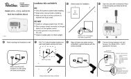
Control Setup<br />
Thetemperature setpoint referstothe temperature atwhich the normally open<br />
(NO) contacts ol the output relay will open. Determine the load (s) to be<br />
controlled and the operating mode required, cooling or heating. Refer to<br />
FiEure 1 for a visual representation.<br />
.When the cooling mode is chosen, the differential is above the setpoint.<br />
The relay will de-energize as the temperature falls to the setpoint.<br />
.When the heating mode is chosen, the differential is below the setpoint.<br />
The relay will de-energize as the temperature rises to the setpoint.
O{ = EliErc€ED<br />
GF=E€I\€RG.r'FD<br />
All control settings are retained in non-volatile memory if power to <strong>ETC</strong> is<br />
interrupted for any reason. Re-programming is not necessary after power<br />
outages or disconnects unless different control settings are required.<br />
u(r f<br />
F<br />
CE<br />
U<br />
L<br />
t!<br />
F<br />
t)<br />
tTi<br />
itri<br />
rm'<br />
lzl<br />
lrl<br />
t>t<br />
lrl<br />
Fioure 1: Setpoint and Ditlerential Settings. Diagram indicates. relay<br />
' 'v-'- '-<br />
on ind otf points in either the heating or cooling modes.<br />
Lockout Switch<br />
The EIC is provided with a lockout switch to prevent tampering by unauthorized<br />
personnel. When placed in the LOCK position, the keypad is disabled<br />
and no changes to the settings can be made. When placed in the UNLOCK<br />
position, the keypad willlunction normally.<br />
To access the lockout switch, disconnect the power supply and open the<br />
control. The switch is located on the inside cover about 2 inches above the<br />
bottom. (see Figure 2). To disable the keypad, slide the switch to the left<br />
LOCK position. To enable the keypad, slide the switch to the right<br />
UNLOCK position. All <strong>ETC</strong> controls are shipped with this switch in the<br />
UNLOCK position,<br />
i<br />
Prooramminq Steps and DisPlaY<br />
iir;tTO Ante piogrammeo'in four simple steps using the LCD display and<br />
the trree keys on the face o{ the control.<br />
Step 1- To starl programming, press the SET key once to access the<br />
Fahrenhert,Cetsius mode. The display willshow the current<br />
slatus, erher F for degrees Fahrenheit or C for degrees Celsius.<br />
Then press either the up I or down I arrow key to toggle<br />
between the F or C designation.<br />
Step 2- Press the SET key again to access the qetpoint. The LCD-<br />
'<br />
* ill display the cuirent setpoint and the 51 annunciator will be<br />
b{inking oir and off to indicate that the control is in the setpoint<br />
mde. -Then press either the up I key to increase or the down ;<br />
key to decrease the sdtpoint to the desired temperature.<br />
Step 3- Press the SET key again to access the differential. The LCD will<br />
'<br />
display the currenl differential and the DIF 1 annunciator will be<br />
blinkirig on and off to indicate that the control is in the differential<br />
mode. -Then press either the up t key to increase or the down ;<br />
key to decrease the differential to the desired setting.<br />
'<br />
Step 4- Press the SET key again to access the cooling^or.heating mode.<br />
The LCD will dispiay the cunent mode, either C1 lor cooling or<br />
H1 for heating. Then press either the up t or down l key to<br />
toggle between the C1 or H1 designation, Press the SET key<br />
once more and programming is complete.<br />
Step Annunciator Description DisPlaY<br />
F or C<br />
Sl (blinking)<br />
DIF 1 (blinking)<br />
c1/H1<br />
Fahrenheit or Celsius Scale<br />
Dirrerentiar remperature tli[E<br />
Cootins or Heatins Mode<br />
l-il<br />
peftl The <strong>ETC</strong> will automatically end programming if no keys are<br />
depressed for a period of thirty seconds. Any settings that have been input<br />
to the control will be accepted at that point.<br />
2<br />
Display Messages<br />
Figure 2: Lockout Switch<br />
IROUBLESHOOTING ERROR l'lESSAGES<br />
E1 - Aopears when either the up I or down 1 key is pressed when<br />
nbi in the programming mode.<br />
To correct: lf the E1 message appears even when no keys are<br />
being pressed, replace the control.<br />
E2 - Appears if the control settings are not properly stored in memory.<br />
To correct: Check all settings and correct if necessary.<br />
EP - Appears when the probe is open, shorted or sensing a temperature<br />
that is out of range.<br />
To correct: Check to see if the sensed temperature is out of<br />
range. lf not, check for probe damage by comparin-g tt to-a<br />
kno-wn ambient temperature between -30"F and 220'F. Replace<br />
the probe if necessary,<br />
EE - Appears if the EEPROM data has been corrupted.<br />
To correct: This condition cannot be field repaired. Replace<br />
the control.<br />
RELAY RATINGS N,O,A.C.<br />
vAc 120 2081240<br />
LRA 96/34.8 48/17 4<br />
FLA 16/5.8 8/2.9<br />
RES A 1515.8 812.9<br />
PILOT DUTYl25VA<br />
USE COPPER<br />
coilOucT08s 0NLY<br />
DISPLAY COOES<br />
F FAHHENHEIT<br />
C CELgUS<br />
H.t HEAT STAGE 1<br />
Cl COOLSTAGE1<br />
EP PROBE FAILUBE.I<br />
OUT OF RANGE<br />
EE EEPROM FAILUHE<br />
El Ii'PROPEB KEY<br />
E2 TE}TORY EEBOB<br />
CL - Appears if calibration mode has been entered.<br />
To correct: Remove power to the control for at least five<br />
seconds. Reapply poriver. lf the CL message still appears,<br />
replace the control.
I I.{STALI,ATION I NSTRUCIIOI.IS<br />
IMPORTANT<br />
1, All <strong>ETC</strong> series controls are designed as operating controls only. lf<br />
an operating control failure could result in personal injury or loss ol<br />
propefi, a separate safety control and /or alarm should be installed.<br />
2. The schematic drawings and other information included in these<br />
installation instructions are lor the purpose of illustration and general<br />
reference onlv.<br />
3. These instric: i^s 00 not expand, reduce, modify or alter the <strong>Ranco</strong><br />
Terms in ar , ttz': and no wananty or remedy in favor of the customer<br />
or an.v c:-.' r€'s3n anses out of these instructions.<br />
4. Hanc: f;l ::r:'cis have been approved by Undennrriter's Laboratories<br />
as !- s:s: ro\rever. approval does rlot extend to their use for any<br />
ot. e' : - T.c s€. <strong>Ranco</strong> assumes no responsibility for any unconventional<br />
a:. :.at :r cf its conirol unless such application has been approved in<br />
,t': ': :,' <strong>Ranco</strong>.<br />
5. l: s :': 'esponsibiliiy of the installer and the user to assure that his or<br />
its app :.a:rcn and use of all <strong>Ranco</strong> products are in compliance with all<br />
federa,. s:ate and local requirements, including, without any limitation,<br />
all rec,. rements imposed under the National Electric Code and any<br />
apc :abie building codes.<br />
CONTROL l4OUtlII}.lG<br />
Mount the <strong>ETC</strong> to a wall or any flat surface ustng a combination of any two<br />
0r more of the slotted holes located on the back of the conirol case. The<br />
control's components are not position sensitive,but should be mounted so<br />
that they can be easily wired and adiusted. Avoid excessive conditions of<br />
moisture, dirt, and corrosive atmosphere.<br />
The <strong>ETC</strong> has provisions for 1/2 inch conduit connections. The conduit hub<br />
should be secured to the conduit before securing the hub to the plastic<br />
housing of the control. When using the conduit enlry in the rear of the case,<br />
a standard plug should be inserled into the conduit hole in the bottom.<br />
Caution should be exercised not to damage the control circuit board or<br />
wiring when installing a conduit connector.<br />
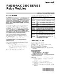
ANALOG OUTPUT<br />
.-- (oPTtoNAL)<br />
24 VAC INPUT<br />
(oPIONAL)<br />
i*<br />
t 0.63<br />
KNOCK.OUT FOF O.5O DIA<br />
CONDUIT TBADE SIZE<br />
O,5O DIA HOLE CONDUIT<br />
TBADE SIZE.88 BEF<br />
BOTTOM VIEW<br />
Figure 3: Dimensions (lnches)
COI.|TROL WIRING<br />
General<br />
All wiring should conform to the National Electric Code and local<br />
regulations.<br />
The total electrical load must not exceed the maximum<br />
rating of the control (see Specifications).<br />
a<br />
a<br />
Use copper conductors only.<br />
Electrical leads shotjld not be taut; allow slack for<br />
temperature change and vibration.<br />
) \<br />
r<br />
lnptfr and Output Widng<br />
For typical wiring diagrams, refer to Figures 4, 5 and 6. All connections are<br />
made to the power (lower) circuit board. When using the 24VAC powered<br />
models, the 24 VAC input lines must enter through the sidewall of the case.<br />
Refer to figure 3 for location of the entry hole.<br />
Figure 7 for wiring.<br />
Analog Output<br />
<strong>ETC</strong> models are available with an optional 0 to 10 volt analog output. This<br />
signal is a linear representation of the sensortemperature with 0volts = -30"F<br />
and 10 volts = 220oF. See figure 8 for wiring information and figure 3 for<br />
location of the entry hole. The reference for this output is designated by the<br />
"-" symbol on the wiring diagram. The output signal is designated by the "+"<br />
symbol.<br />
240 VOLT<br />
LOAD<br />
1<br />
ul_<br />
240 VAC<br />
Figure 5: Typicat Wiring Diagram lor 240 VAC Power Input and<br />
Line Voltage Switching.<br />
) \<br />
I<br />
120 VOLI<br />
LOAD<br />
.".8!<br />
,-f\Y./r.\-l I I<br />
rrL<br />
120 VAC<br />
240 VAC<br />
OR<br />
120 VAC<br />
240 VAC<br />
OR<br />
1 20 VAC<br />
Figure 4: Typicat Line Voltage Wiring Diagram.<br />
Figure 6: Ditferent Voltage to Control and Ditlerent Voltage Load.
SENSOR t'lOU]'|TIl'lc<br />
For space sensing, mount the sensor where it will be unaffected<br />
by heaVcool discharge or radiated heat sources. Spot sensing<br />
requires the sensor to be in good contact with the surface being<br />
sensed. The sensor can be inserted in a bulb well for immersion<br />
sensing.<br />
24 VAC<br />
CLASS 2<br />
E)(IEl.lDING SE}{SOR<br />
CAUTI0N: Sensorwiring splices maybe madeexternal from the<br />
control. D0 NOT attempt to unsolder the sensor at the control<br />
circuit board!<br />
CAUTION: Disconnect power to control before wiring to avoid<br />
possible electrical shock or damage to the controller.<br />
VOLTAGE<br />
Figure 7: TypicalWiring Diagramtor 24 VAC Power lnput and<br />
Line Voltage Switching.<br />
Additionalcable can be spliced tothe sensorcableto increasethe<br />
length beyond the standard 8 feet. lt can be extended up to 400<br />
feet. The cable should be at least 22 AWG or larger to keep<br />
additional resistance to a minimum.<br />
All splices and wire lengths added to the sensor cable should be<br />
made according to acceptable wiring practices and should conform<br />
to the National Electrical Code and local regulations. Use<br />
copper conductors only. Shielded cable is not required.<br />
Checkout Procedure<br />
1. Before applying power, make sure installation and wiring<br />
connections are correct.<br />
rl<br />
a)<br />
IIII<br />
EEtrED<br />
s@t<br />
Effi}#<br />
:t-<br />
N@O<br />
Ltrt-E ErJ<br />
NCNOC<br />
+<br />
0-t0v<br />
ANALOG OUTPUT<br />
Figure 8: 0-10 V Analog Output Located on Power (Lower) Circuit Board.<br />
4.<br />
Apply power to the control and obserye one or more cycles<br />
of operation.<br />
lf performance indicates a problem, check sensor<br />
resistance to determine if sensor or control is at fault.<br />
To check sensor resistance, disconnect sensor and<br />
measure the resistance across the leads while measuring<br />
temperature at the sensor.<br />
TEl'lPERATURE Al/ERAGING<br />
SENSOR<br />
SENSOR<br />
(4) Sensors wited in series/parallel for temperaturc averaging,<br />
SENSOR<br />
SENSOR<br />
FIELD REPAIRS<br />
Field calibrating or repairs to the <strong>ETC</strong> control must not be attempted. Sensors<br />
and replacement controls are available through <strong>Ranco</strong> wholesalers.
Replacement Sensor - Order<br />
Part No. 1309007-044<br />
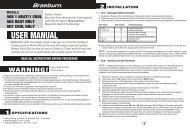
SPECITICATIONS<br />
The 1309007-044 sensor is a negative temperature coefficient<br />
(NTC)thermistor sensr. The sensor resistance decreases wittr<br />
temperature increase. lt is .25 x 1.94 long with 8 feet #22 AWG<br />
cable. The thermistor has a relerence resistance of 30,000 ohms<br />
at77"F (25t).<br />
za<br />
The schemalic drawings and other information included in these instructions<br />
are forthe purpose of illustration and general reference only. <strong>Ranco</strong><br />
assumes no responsibility for any unconventional application of this<br />
control, unless such application has been approved in writing by <strong>Ranco</strong>.<br />
Deg.C. Deg. E HES. Nom.<br />
-40<br />
-30<br />
-20<br />
-10<br />
0<br />
10<br />
20<br />
25<br />
30<br />
40<br />
50<br />
60<br />
70<br />
80<br />
90<br />
100<br />
110<br />
Figure 10 :<br />
Resisiance vs Temperature of 1309ffi7-044. Sensor including 8 foot cable.<br />
-40<br />
-22<br />
-4<br />
14<br />
32<br />
50<br />
68<br />
77<br />
86<br />
104<br />
122<br />
140<br />
158<br />
176<br />
194<br />
212<br />
230<br />
't,010,000<br />
531,000<br />
291,200<br />
166,000<br />
92960<br />
59,700<br />
37,470<br />
30,000<br />
24,170<br />
15,980<br />
10,810<br />
7,464<br />
5,200<br />
3,774<br />
2,753<br />
2,036<br />
1,53'l<br />
RARSG@<br />
<strong>Ranco</strong> North America<br />
8115 U.S. Rt. 42 North<br />
Plain City, Ohio 43054<br />
C',*<br />
lnvenays Company