CZ-4 MASTER CONTROL PANEL - Emerson Climate Technologies
CZ-4 MASTER CONTROL PANEL - Emerson Climate Technologies
CZ-4 MASTER CONTROL PANEL - Emerson Climate Technologies

Create successful ePaper yourself
Turn your PDF publications into a flip-book with our unique Google optimized e-Paper software.
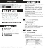
<strong>CZ</strong>-4<br />
<strong>MASTER</strong> <strong>CONTROL</strong> <strong>PANEL</strong><br />
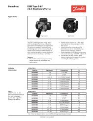
Purge Override<br />
Button<br />
System Model Indicator LED<br />
Power Indicator LED<br />
Boot Button<br />
Adjustable Second<br />
Stage Timer<br />
Adjustable Heating Limit<br />
RJ11 Connection<br />
Sensor Terminals<br />
Zone Terminal Blocks for<br />
Zone Damper Motors and<br />
Zone Thermostats<br />
HVAC Equipment Terminals<br />
24 VAC Transformer<br />
Terminals<br />
Re-Settable Fuse<br />
Mounting Keyholes<br />
Two at Top also<br />
Zone Calling Indicators<br />
Mode DIP Switches<br />
The <strong>CZ</strong>-4 basic function is zone control. On a call for heating or cooling,<br />
the panel will accept the first call from any zone. Upon accepting<br />
this call, the <strong>CZ</strong>-4 will open the damper(s) to the zone calling, close<br />
the damper(s) to those areas not calling, activate the needed HVAC<br />
controls for heating or cooling, whichever is being called and not accept<br />
any calls for the opposite mode.<br />
Any calls for the opposite mode will be locked out until the initial mode<br />
is either satisfied or a period of time has elapsed that is sufficient for<br />
the first mode to satisfy, a maximum of 20 minutes. A Patent Pending<br />
sequence determines the time the unit has been running or needs to<br />
continue to run in order to adequately provide conditioning for each<br />
mode. If a particular mode has already been calling for 20 minutes or<br />
longer and an opposite call comes in the <strong>CZ</strong>-4 will immediately drop<br />
the mode, enter the purge mode in order to dissipate the conditioned<br />
air into the zones calling before switching over to provide the new<br />
conditioning call to its zones.<br />
When using the <strong>CZ</strong>-4 to control two stage heating and/or cooling, the<br />
second stage is controlled based upon time after the first stage call<br />
from the thermostat. When any zone calls the panel’s built-in timer<br />
begins and after the set period of time elapses, the <strong>CZ</strong>-4 will also activate<br />
the W3 for Heating or Y2 for Cooling. The Second Stage Timer<br />
is adjustable from 5 to 23 minutes after the first stage calls. Once the<br />
second stage is on, it will continue to run until the first stage is satisfied<br />
or the limit setting is reached.<br />
Once all zone thermostats are satisfied for heating and cooling, the<br />
<strong>CZ</strong>-4 can now accept Fan calls allowing Continuous Air Circulation<br />
(CAC) in those zones where the thermostat’s Fan Switch is set to ON.<br />
These zone dampers will be Open while the dampers to the zones<br />
where the Fan Switch is set to AUTO will be CLOSED.<br />
When all zone thermostats are satisfied for both Heating and Cooling<br />
and all Fan switches are set to AUTO position, the HVAC unit will be<br />
off and all zone dampers will return to a normally open position. Once<br />
a zone calls for heating, cooling or fan, the dampers to the calling<br />
zones remain open and dampers to the zones not calling will close.<br />
SET-UP FOR VARIOUS HVAC EQUIPMENT<br />
The <strong>CZ</strong>-4 is factory set for conventional fossil fuel (oil or gas) single or<br />
two stage heating and cooling. The panel only needs to be configured<br />
when using with a conventional electric furnace or hydro-air system<br />
in order to bring the fan on with a call for heat, or when using with a<br />
heat pump.<br />
Most all of the panel configuration is done by setting the DIP switches<br />
in the lower center of the panel. Below is shown their setting and<br />
functions.<br />
ON<br />
OFF<br />
1 2 3 4 5 6<br />
7 8<br />
1. HT PMP EQP – Heat Pump Equipment – This switch changes the<br />
output of the HVAC Equipment terminals from conventional Heating<br />
and Cooling to a traditional Heat Pump Output. When OFF, a<br />
heat call activates the W1 output. When ON, a Heat call activates<br />
the Y1 output to bring on the compressor.<br />
2. FAN IN HEAT – Activates the O output to turn the Fan on with a<br />
call for Heat. This is used for Heat Pumps, Electric Heat furnaces<br />
and Hydro-Air Systems. In the OFF position the <strong>CZ</strong>-4 will not<br />
activate the Fan in heating unless there is a fan call from one of<br />
the zone thermostats.<br />
3. STAT O TO W – Switch is placed to ON when using Heat Pump<br />
thermostats that use an O terminal to activate the reversing valve<br />
in COOLING. The O on the thermostat is wired to W on the zone<br />
terminal in order to determine if the call is for heating or cooling.<br />
All zone thermostats must operate and be wired the same way.<br />
4. STAT B TO W – Switch is used when using Heat Pump thermostats<br />
that use a B terminal to activate the reversing valve in HEAT-<br />
ING. The B terminal on the thermostat is wired to W on the zone<br />
terminal in order to determine if the call is for heating or cooling.<br />
All zone thermostats must operate and be wired the same way.<br />
TECHNICAL HELP<br />
www.white-rodgers.com 241
<strong>CZ</strong>-4<br />
OPERATION AND WIRING<br />
4. STAT B TO W (cont.)<br />
NOTE: Some OEMs use the B terminal as a transformer<br />
Common and not as the heating reversing valve. These<br />
thermostats will use the O terminal for the reversing valve<br />
and should be wired accordingly using DIP Switch #3. The B<br />
terminal will then be wired to the C terminal on the thermostat<br />
terminal block.<br />
5. FAN IN PRG – This switch keeps the fan running during the purge<br />
time in order to dissipate the conditioned air into the last zone(s)<br />
calling. Placing this switch to ON prevents the fan from turning off<br />
from the fan control in the HVAC Unit during the purge mode and<br />
coming back on moments later if another call is waiting. In OFF<br />
the fan will be controlled by HVAC Fan controls. This is desirable<br />
in residential applications to prevent cold drafts after heating by<br />
having the switch OFF.<br />
6. CNTL 1 – EMERGENCY HEAT – This switch can be used to place<br />
all zones into the Emergency Heat mode. This switch would be<br />
used when single stage thermostats are used. NOTE: There is no<br />
indication on the panel to show this switch is ON.<br />
7. CNTL 2 – Future Use.<br />
8. CNTL 3 – Future Use.<br />
One of the many features of the DIP switches is if at anytime the<br />
equipment is changed from single stage to heat pump or vice versa<br />
the thermostats do not need to be changed with the equipment<br />
change. Changing the DIP switch settings is all that is needed.<br />
WIRING<br />
The <strong>CZ</strong>-4 is very simple to wire and requires only a minimum number<br />
of connections. The <strong>CZ</strong>-4 terminal blocks are screwless and all wires<br />
can easily be pushed into their respective terminal by depressing<br />
the button for each point and releasing once the wire is seated. To<br />
remove the wire, just press its button again and remove the wire.<br />
Zone Dampers – The <strong>CZ</strong>-4 can power any 24VAC damper, either<br />
2 wire or 3 wire. See specific wiring instructions with the damper or<br />
inside panel cover.<br />
Zone Thermostats – The thermostats wiring will be for single stage<br />
(Y-G-R-W-C) or Heat Pump (Y-G-R-E-C and O or B). This wiring is<br />
shown on diagrams 1 for single stage and 3 for heat pumps.<br />
Equipment – The HVAC equipment will follow wiring diagram 2 for<br />
single and two stage systems or 4 for heat pump systems.<br />
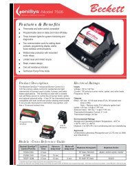
WIRING DIAGRAM 2 – Single Stage and Two Stage<br />
Equipment<br />
EQUIPMENT<br />
SINGLE STAGE and TWO STAGE CONNECTIONS<br />
W2<br />
E<br />
W1<br />
R<br />
G<br />
B<br />
O<br />
Y1<br />
Y2<br />
<strong>CZ</strong>4<br />
HVAC EQUIPMENT<br />
Second Stage Heat Relay<br />
First Stage Heat Relay<br />
R 24V. Transformer C<br />
Fan Relay<br />
First Stage Compressor<br />
Relay<br />
Second Stage Cooling<br />
Relay<br />
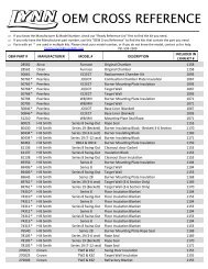
WIRING Diagram 3 – Heat Pump Thermostat<br />
HEAT PUMP THERMOSTAT<br />
C O/B R Y G<br />
To Damper Motor<br />
See Damper Wiring<br />
Instructions<br />
E<br />
Power Closed<br />
Power Open<br />
24VAC Common<br />
<strong>CZ</strong>4<br />
E<br />
G<br />
Y<br />
R<br />
W/O/B<br />
C<br />
CLOSE<br />
OPEN<br />
COM<br />
WIRING DIAGRAM 4 – Heat Pump Equipment<br />
EQUIPMENT<br />
HEAT PUMP CONNECTIONS<br />
W2<br />
E<br />
W1<br />
R<br />
G<br />
B<br />
O<br />
Y1<br />
Y2<br />
<strong>CZ</strong>-4<br />
HEAT PUMP <strong>CONTROL</strong>S<br />
Second Stage Heat Relay<br />
First Stage Heat Relay<br />
24V. Transformer<br />
Fan Relay<br />
Reversing Valve<br />
Compressor Relay<br />
ZONE THERMOSTAT<br />
DAMPER<br />
TECHNICAL HELP<br />
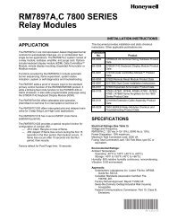
WIRING DIAGRAM 1 – Single Stage Thermostat<br />
SINGLE STAGE THERMOSTAT<br />
C W R Y G E <strong>CZ</strong>-4<br />
Zone Terminals<br />
To Damper Motor<br />
See Damper Wiring<br />
Instructions<br />
Power Closed<br />
Power Open<br />
24VAC Common<br />
E<br />
G<br />
Y<br />
R<br />
W/OB<br />
C<br />
CLOSE<br />
OPEN<br />
COM<br />
ZONE THERMOSTAT<br />
DAMPER<br />
STAGE TIMER<br />
The <strong>CZ</strong>-4 has a built-in stage timer that eliminates the need and<br />
added cost of using two stage thermostats. On a call for either heating<br />
or cooling the timer begins. A minimum of 5 minutes, adjustable to<br />
a maximum of 23 minutes, can be set in order to activate the W2 or<br />
Y2 outputs after the first stage call.<br />
The Stage Timer is marked 0 through 9 and each increment is indented<br />
as the dial is rotated. A minimum 5 minutes is set when the dial is<br />
set to 0. To calculate the stage timing the dial setting is multiplied by 2<br />
and added to the base of 5 minutes. Example: Dial setting is 3 x 2 = 6<br />
+ 5 = 11 Minutes for the Stage Timer.<br />
STG Time<br />
5 MIN + 2X<br />
4 5 6<br />
3<br />
2<br />
1<br />
0<br />
7<br />
8<br />
9<br />
242<br />
www.white-rodgers.com
<strong>CZ</strong>-4<br />
OPERATION AND WIRING<br />
PURGE TIME<br />
The <strong>CZ</strong>-4 has a built-in Purge Time after each call is satisfied and<br />
provides a minimum off time before another call is initiated. The<br />
Purge Time is set at 2.5 minutes after all calls for a particular mode<br />
are satisfied or when the Changeover Timer requires a changeover<br />
due to opposing calls.<br />
After all calls are satisfied or the changeover timer activates, the<br />
Purge Timer begins and the heating or cooling, whichever was on,<br />
is deactivated. Typically the fan may be running during this time and<br />
the damper(s) to the last zone(s) calling will remain open to purge<br />
the conditioned air only into those zones that were calling for the<br />
conditioning.<br />
DIP Switch 5 can be set ON to keep the Fan running during the Purge<br />
mode in order to prevent the fan cycling off and back on between<br />
modes. In the instance where the Fan staying ON may create a draft,<br />
and the frequency of opposite calls is minimal this switch can be kept<br />
to OFF.<br />
The CLR PRGE button on the top left of the panel can be pushed to<br />
override the Purge mode and speed installation and checkout. This<br />
button is only active when the System LED is AMBER.<br />
Leading Air Sensor<br />
TECHNICAL HELP<br />
www.white-rodgers.com 243
<strong>CZ</strong>-4/CAZ-2 ADDING ZONES<br />
AND TROUBLESHOOTING<br />
MINIMUM ON TIMER<br />
The <strong>CZ</strong>-4 also has a minimum on time whenever the compressor<br />
operates in order to prevent frequent short cycling. Once there is a<br />
call for cooling or the compressor on a heat pump, the <strong>CZ</strong>-4 will hold<br />
that call for a period of 2 minutes.<br />
CHANGEOVER TIMER<br />
Whenever a call is made for either heating or cooling, the changeover<br />
timer is activated in order to track the amount of time heating<br />
or cooling is on. When an opposite call is made after a first call is<br />
existing the changeover timer calculates the amount of time the unit<br />
has already been supplying the first mode in order to determine how<br />
long it will hold off the opposite call. If an opposite call is made shortly<br />
after the first call, the opposite call may be held off for as much as 20<br />
minutes. If the first call or subsequent calls for the first call mode has<br />
had that mode operating for up to 20 minutes already and an opposite<br />
call comes in after 20 minutes, the changeover timer will immediately<br />
recognize the opposite call, shutting off the current mode, enter the<br />
purge mode and automatically switch to the opposite mode.<br />
The longer a call has been running, up to 20 minutes, the shorter the<br />
wait time will be for an opposite call. If a call is over 20 minutes and<br />
an opposite call is made the changeover will be immediate following<br />
the purge time. This intelligent changeover timing makes the <strong>CZ</strong>-4<br />
unique to any other zoning system.<br />
CAZ-2<br />
The Zone Panel can be added onto with Model CAZ-2. The CAZ-2 is<br />
available as a 2 zone adder panel and expands any <strong>CZ</strong>-4 panel to an<br />
almost unlimited number of zones. The CAZ-2 panel is connected by<br />
a 6 conductor RJ11 telephone cable. This makes wiring between the<br />
<strong>CZ</strong>-4 and CAZ-2 literally a snap.<br />
CHECKOUT<br />
The <strong>CZ</strong>-4 has unique features that simplify the checkout of the<br />
system and has LED readouts that constantly indicate the system<br />
operation. Once 24 Volt Power is applied to the panel, the Green<br />
Power LED will illuminate. This will stay illuminated constantly when<br />
power is applied.<br />
The System LED will provide several different indications based upon<br />
color and if it is flashing.<br />
Heat ON – RED<br />
Heat Limit – RED Flashing<br />
Cool ON – GREEN<br />
Cool Limit – GREEN Flashing<br />
FAN ON – AMBER<br />
PURGE – AMBER Flashing<br />
TROUBLESHOOTING<br />
The <strong>CZ</strong>-4 is a very simple control to troubleshoot, especially with the<br />
LED indicators. The only other device needed is a simple Volt/Ohm<br />
meter. Almost all problems can be traced to an external component<br />
or wiring to the <strong>CZ</strong>-4. While the <strong>CZ</strong>-4 has been designed to operate<br />
under extreme voltage conditions and is fuse protected, like any<br />
computer the micro-processor can hang up and not operate properly.<br />
For those instances a BOOT button has been installed that re-boots<br />
the micro-processor just like your computer. Pressing this button for a<br />
few seconds and then releasing it will allow the micro-processor to reboot<br />
and in most all cases eliminate the problem. If not, the following<br />
procedure can help isolate the problem.<br />
ZONE(S) NOT CALLING<br />
Each zone has a Green LED next to the zone relay when it is calling<br />
and that calling is being recognized by the <strong>CZ</strong>-4. If a zone is supposed<br />
to be calling and the Zone LED is not on, check for 24VAC<br />
across the thermostat terminal C and the Y, if a Cool call, W if a Heat<br />
call, or G if a Fan call. If there is no voltage here at the panel, the<br />
panel is not getting the signal from the thermostat. The problem is<br />
mis-wiring, a broken wire or a problem in the thermostat. To check the<br />
zone on the panel, place jumper from R to Y, R to W or R to G to see<br />
that the panel is operating properly.<br />
ZONE(S) WILL NOT SHUT OFF<br />
If a zone will not stop calling, the Zone LED should still be on. Depending<br />
on the call, disconnect the Y, W or G wire from the terminal<br />
strip. The zone will drop out. Check the thermostat wiring for a miswiring<br />
or short that keeps the zone calling.<br />
DAMPER MOTOR CHECKOUT<br />
To checkout the dampers, the panel provides 24VAC to the COM<br />
and OPEN when the damper is to be open and 24VAC to COM and<br />
CLOSE when the damper is to be CLOSED. When any zone is calling<br />
and its Green LED is ON, there is 24VAC across COM and OPEN.<br />
The only time a damper will close is when another zone is calling<br />
and its zone is not calling. In this instance there will be 24VAC across<br />
COM and CLOSE.<br />
TECHNICAL HELP<br />
Each zone has its own small Green indicator LED next to each zone<br />
relay. This light is lit when the specific zoning is calling for the mode<br />
shown on the System LED.<br />
244<br />
www.white-rodgers.com