Tac Erie Vt/Vs Poptop Series Two Position Spring Return Valves - Kele
Tac Erie Vt/Vs Poptop Series Two Position Spring Return Valves - Kele
Tac Erie Vt/Vs Poptop Series Two Position Spring Return Valves - Kele

You also want an ePaper? Increase the reach of your titles
YUMPU automatically turns print PDFs into web optimized ePapers that Google loves.
TAC<br />
1354 Clifford Avenue<br />
P. O. Box 2940<br />
Loves Park, IL 61132-2940<br />
www.tac.com<br />
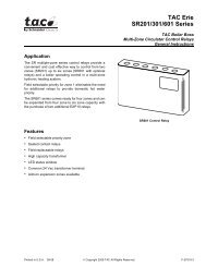
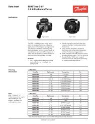
TAC <strong>Erie</strong> VT/VS PopTop <strong>Series</strong><br />
<strong>Two</strong> <strong>Position</strong> <strong>Spring</strong> <strong>Return</strong> <strong>Valves</strong><br />
General & High Close-Off PopTop Zone <strong>Valves</strong><br />
General Instructions<br />
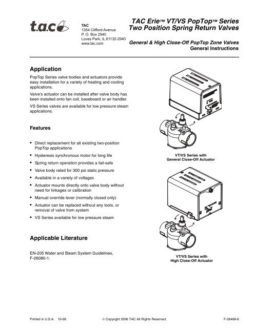
Application<br />
PopTop <strong>Series</strong> valve bodies and actuators provide<br />
easy installation for a variety of heating and cooling<br />
applications.<br />
Valve’s actuator can be installed after valve body has<br />
been installed onto fan coil, baseboard or air handler.<br />
VS <strong>Series</strong> valves are available for low pressure steam<br />
applications.<br />
Features<br />
• Direct replacement for all existing two-position<br />
PopTop applications<br />
• Hysteresis synchronous motor for long life<br />
• <strong>Spring</strong> return operation provides a fail-safe<br />
• Valve body rated for 300 psi static pressure<br />
• Available in a variety of voltages<br />
• Actuator mounts directly onto valve body without<br />
need for linkages or calibration<br />
• Manual override lever (normally closed only)<br />
• Actuator can be replaced without any tools, or<br />
removal of valve from system<br />
• VS <strong>Series</strong> available for low pressure steam<br />
VT/VS <strong>Series</strong> with<br />
General Close-Off Actuator<br />
Applicable Literature<br />
EN-205 Water and Steam System Guidelines,<br />
F-26080-1.<br />
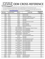
VT/VS <strong>Series</strong> with<br />
High Close-Off Actuator<br />
Printed in U.S.A. 10-06 © Copyright 2006 TAC All Rights Reserved. F-26496-6
SPECIFICATIONS<br />
Valve Body Assembly<br />
Actuator<br />
Service Hot and chilled water models, up to 50% glycol. Steam models up to 15 psi (both<br />
valve body and valve actuator must be rated for high temperature).<br />
System Static Pressure Limits 300 psi (2068.4 kPa).<br />
Close-off Refer to Table-2.<br />
Fluid/Ambient Temperature Limits Refer to Table-1.<br />
Seat Leakage ANSI class IV (0.01%) with pressure at inlet (B-port/A-port, if 3-way).<br />
Body Forged brass.<br />
Stem Nickel-plated.<br />
Seat Brass.<br />
Paddle (VT series) Buna N.<br />
Paddle (VS series) Highly saturated nitrile.<br />
Voltage 24 Vac @ 50/60 Hz. 110 Vac @ 50 Hz. and 120 Vac @ 60 Hz., 230 Vac @ 50 Hz.<br />
and 240 Vac @ 60 Hz., 208 Vac @ 50/60 Hz., 277 Vac @ 50/60 Hz.<br />
Power Requirements 6.5 watts, 7.5 Va.<br />
End Switch 24 - 240 Vac Models: 24 - 240 Vac/101 mA min. to 5A max, and 9 - 30 Vdc @<br />
100 mA max.<br />
277 Vac Models: 277 Vac/101 mA min. to 5A max.<br />
Control Signal On/off, 2 position, spring return.<br />
Timing, Full Open to Full Close 25 Sec max for 60 Hz; 30 Sec max for 50 Hz; and 9 Sec<br />
max spring return.<br />
Materials Stainless steel base plate, aluminum cover.<br />
Ambient Temperature Limits:<br />
Shipping & Storage, -40 to 160 °F (-40 to 71°C).<br />
Operating, Refer to Table-1.<br />
Humidity 5 to 95% relative humidity, non-condensing.<br />
Agency Listings UL873: Underwriters laboratories (File #E9429 Catagory Temperature<br />
Indicating and Regulating Equipment). CUL: UL Listed for use in Canada by Underwriters<br />
Laboratory. Canadian Standards C22.2 No. 24. European Community: EMC Directive<br />
(89/336/EEC). Low Voltage Directive (72/23/EEC). Australia: This product meets<br />
requirements to bear the C-Tick Mark according to the terms specified by the<br />
Communications Authority under the Radio Communications Act of 1992.<br />
Shipping Weight (Actuator/Valve Assembly) 2.25 lbs (1020 g).<br />
Table-1 Valve Body and Actuators Model Chart<br />
Model<br />
VTXXXX<br />
VSXXXX<br />
AXX3XXX<br />
AXX4XXX<br />
Temperature Range<br />
32° to 200 °F (fluid) @ 104 °F (Ambient) (0 to 93 °C @ 40 °C)<br />
32° to 250 °F (fluid) @ 169 °F (Ambient) (0 to 121 °C @ 76 °C), and/or 15 PSI (103 kPa) Steam a<br />
32° to 200 °F (fluid) @ 104 °F (Ambient) (0 to 93 °C @ 40 °C)<br />
32° to 250 °F (fluid) @ 169 °F (Ambient) (0 to 121 °C @ 76 °C), and/or 15 PSI (103 kPa) Steam a<br />
a: For steam applications both valve body and valve actuator must be rated for high temperature.<br />
Example: VS2213G14A020 = Assembly. VS2213 = Valve body. AG14A020 = Actuator.<br />
Accessories for Inverted Flare Connection <strong>Valves</strong><br />
3/4" inverted flare bodies accept the following adapters to copper pipe:<br />
436-214-1 Union nut & elbow assembly, female for 1/2" (5/8" O.D.) copper, 15/16" long<br />
436-220 Union nut & coupling assembly, female for 1/2" (5/8" O.D.) copper, 1-1/16" long<br />
436-252 Union nut & coupling assembly, female for 3/4" (7/8" O.D.) copper, 1-27/32"<br />
long<br />
436-229-3 Union nut & nipple assembly, male for 1/2" (5/8" O.D.) copper, 3" long<br />
436-214-4 Union nut & elbow assembly, male for 1/2" (5/8" O.D.) copper, 1-15/16" long<br />
436-256 Union nut & coupling assembly, female for 1" (1-1/8" O.D.) copper, 1-3/8" long<br />
2 © Copyright 2006 TAC All Rights Reserved. F-26496-6
Table-2 Flow Coefficients & Maximum Close-Off Pressure Differential<br />
Valve<br />
Size<br />
Connection Type 2-way Cv (kv) 3-way Cv (kv)<br />
(G)* Close-Off ΔP<br />
PSI (kPa)<br />
(H)† PSI Close-Off ΔP<br />
(kPa)<br />
1/2" NPT, SW, Rp, SAE<br />
3/4" IFL<br />
1/2" NPT, SW, Rp, SAE<br />
3/4" NPT, SW, IFL, Rp<br />
1.0 (0.9) 1.5 (30) 60 (414) 75 (517)<br />
2.5 (2.2) 3.0 (2.6) 40 (276) 50 (344)<br />
1/2" NPT, SW, SAE, Rp<br />
3/4" NPT, SW, IFL, Rp<br />
3.5 (3.0) 4.0 (3.4) 25 (172) 30 (208)<br />
1" SW<br />
3/4" NPT, SW, Rp<br />
1" SW<br />
5.0 (4.3) 5.0 (4.3) 20 (137) 25 (172)<br />
3/4" NPT, SW, Rp 7.5 (6.5) 7.5 (6.5) 17 (117) 20 (137)<br />
1" NPT, SW, Rp<br />
1-1/4" SW<br />
8.0 (6.9) 8.0 (6.9) 17 (117) 20 (137)<br />
Valve Body Legend<br />
NPT — Threaded (female)<br />
SW — Sweat<br />
IFL — Inverted Flare<br />
SAE — Society Automotive Engineers Flare (male)<br />
Rp — "Metric" Threaded (female)<br />
* G = General close off actuator<br />
† H = High close off actuator<br />
Table-3 Water Valve Sizing Table*<br />
ΔP 1.0 Cv 1.5 Cv 2.5 Cv 3.0 Cv 3.5 Cv 4.0 Cv 5.0 Cv 7.5 Cv 8.0 Cv<br />
1 PSI 1.0 1.5 2.5 3.0 3.5 4.0 5.0 7.5 8.0<br />
Differential<br />
Pressure, ΔP<br />
2 PSI 1.4 2.1 3.5 4.2 4.9 5.7 7.1 10.6 11.3<br />
3 PSI 1.7 2.6 4.3 5.2 6.1 6.9 8.7 13.0 13.9<br />
4 PSI 2.0 3.0 5.0 6.0 7.0 8.0 10.0 15.0 16.0<br />
5 PSI 2.2 3.4 5.6 6.7 7.8 8.9 11.2 16.8 17.9<br />
* Water capacity in gallons per minute (GPM).<br />
F-26496-6 © Copyright 2006 TAC All Rights Reserved. 3
Body Type &<br />
Temperature<br />
T = On/Off (General)<br />
S = On/Off (Steam)<br />
High temperature<br />
actuator must be used.<br />
Configuration<br />
2 = 2-Way<br />
3 = 3-Way<br />
Valve Size<br />
2 = 1/2"<br />
3 = 3/4"<br />
4 = 1"<br />
5= 1-1/4"<br />
Connection Type 3 Availability<br />
1 = Sweat 1/2", 3/4", 1", 1-1/4"<br />
2 = Threaded NPT 1/2", 3/4", 1"<br />
3 = Threaded Rp (metric) 1/2", 3/4", 1"<br />
4 = Inverted Flare (Retrofit) 3/4"<br />
5 = SAE Flare 1/2"<br />
Part Numbering System<br />
<strong>Two</strong> <strong>Position</strong> Zone <strong>Valves</strong>, <strong>Spring</strong> <strong>Return</strong> Actuators<br />
1<br />
CV Size<br />
V X X X X X X X X X XX X<br />
Options<br />
0 = No Options<br />
A = End Switch 4<br />
Electrical Leads<br />
00 = 6" Motor Wires<br />
01 = Terminal Block with End Switch<br />
(General Temp., 24 VAC only)<br />
02 = 18" (Standard) Wire Leads<br />
Voltage<br />
A = 24 VAC, 50/60 HZ<br />
B = 110 VAC, 60 HZ, 120 VAC, 50 HZ<br />
D = 208 VAC, 50/60 HZ<br />
T = 277 VAC, 50/60 HZ<br />
U = 230 VAC, 50 HZ and 240 VAC, 60 HZ<br />
Temperature Ratings<br />
3 = General Temperature<br />
4 = High Temperature<br />
<strong>Spring</strong> <strong>Return</strong><br />
Actuator Type<br />
G = On/Off (General Close-Off)<br />
H = On/Off (High Close-off)<br />
2<br />
Availability<br />
1 = Normally Closed 2-way and 3-way<br />
2 = Normally Open 2-way only<br />
5 6<br />
5<br />
No. 2-way 3-way Size Connection Type<br />
1 = 1.0 1.5 1/2" 1, 2, 3, 5<br />
3/4" 4<br />
2 = 2.5 3.0 1/2" 1, 2, 3, 5<br />
3/4" 1, 2, 3, 4<br />
1/2" 1, 2, 3, 5<br />
3 = 3.5 4.0 3/4" 1, 2, 3, 4<br />
1" 1<br />
5 = 5.0 5.0 3/4" 1, 2, 3<br />
1" 1<br />
7 = 7.5 7.5 3/4" 1, 2, 3<br />
8.0 8.0 1" 1, 2, 3<br />
1-1/4" 1<br />
1<br />
2<br />
3<br />
4<br />
When ordering valve body only: use the first<br />
six positions to configure the valve.<br />
When ordering actuator only use the last seven positions<br />
to configure the actuator. Prefix with the letter "A".<br />
TAC inverted flare fittings must be ordered separately.<br />
See actuator accessories for fitting part numbers.<br />
End switch is not available for 277 Vac models if<br />
actuator temperature rating is high temperature (4).<br />
5 Actuators with Terminal blocks require endswitch and<br />
the endswitch is 24 Vac @ 101 mA min. -5A max.<br />
6 End switch is 24 - 240Vac @ 101 mA min. to 5 A max. and<br />
9-30 Vdc @ 100 mA max for actautors rated 240V or less.<br />
End switch is 277Vac @ 101 mA min. to 5A max for<br />
actuators rated 277V.<br />
Body & Actuator Combination Requirements<br />
Temperature Configurations<br />
Body Configuration<br />
V T X X X X<br />
T = General<br />
S = Steam<br />
If body configuration is T, actuator temp rating can be 3 or 4.<br />
If body configuration is S, actuator temp rating must be 4.<br />
Actuator <strong>Spring</strong> <strong>Return</strong> Mode<br />
A X X 3 X X X X<br />
3 = General Temperature<br />
4 = High Temperature<br />
If actuator temp rating is 3, body style must be T.<br />
If actuator temp rating is 4, body style can be S or T.<br />
Example:<br />
Assembly: VT2213G13A020. Components: VT2213 = Body. AG13A020= Actuator.<br />
The actuator part number is prefixed with the letter "A".<br />
4 © Copyright 2006 TAC All Rights Reserved. F-26496-6
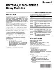
TYPICAL APPLICATION (wiring diagram)<br />
Honeywell - Wire Leads<br />
Honeywell - Terminal Block<br />
L1<br />
(HOT)<br />
L2<br />
THERMOSTAT<br />
To Aux. Circuit<br />
Black<br />
Black<br />
Red<br />
Red<br />
Motor<br />
End Switch<br />
L1<br />
(HOT)<br />
L2<br />
THERMOSTAT<br />
End Switch<br />
ES<br />
Motor<br />
TR<br />
TH<br />
ES<br />
TR<br />
TH<br />
To Aux. Circuit<br />
TAC <strong>Erie</strong> Wire Leads<br />
TAC <strong>Erie</strong> Terminal Block<br />
L1<br />
(HOT)<br />
L2<br />
THERMOSTAT<br />
Black<br />
Black<br />
Red<br />
Red<br />
Motor<br />
End Switch<br />
L2<br />
L1<br />
(HOT)<br />
THERMOSTAT<br />
TH<br />
TR<br />
TR<br />
TH TH<br />
Motor<br />
ES ES<br />
End Switch<br />
To Aux. Circuit<br />
Figure-1 Typical Wiring of a PopTop to Replace a Honeywell Valve<br />
To Aux. Circuit<br />
24 V 5A max<br />
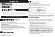
TAC <strong>Erie</strong> Wire Leads<br />
THERMOSTAT<br />
6<br />
5<br />
White - Rodgers (1311 or 1321)<br />
THERMOSTAT<br />
6 5<br />
4<br />
Motor<br />
5<br />
4<br />
6<br />
End Switch<br />
3<br />
2<br />
1<br />
To Aux. Circuit<br />
L1<br />
(Hot)<br />
L2<br />
L1<br />
(Hot)<br />
L2<br />
4<br />
Black<br />
Black<br />
Red<br />
Red<br />
Motor<br />
End Switch<br />
TAC <strong>Erie</strong> Terminal Block<br />
L2<br />
L1<br />
(HOT)<br />
6<br />
4<br />
5<br />
TH<br />
Motor<br />
TR TH<br />
TR<br />
TH<br />
End Switch<br />
ES ES<br />
THERMOSTAT<br />
Figure-2 Typical Wiring of a PopTop to Replace a Flair or White-Rodgers 3-Wire Valve<br />
To Aux. Circuit<br />
24 V 5A max<br />
F-26496-6 © Copyright 2006 TAC All Rights Reserved. 5
Flair - Terminal Block<br />
<strong>Tac</strong>o - Terminal Block<br />
L1<br />
(HOT)<br />
THERMOSTAT<br />
1 4 5<br />
L1<br />
(HOT)<br />
L2<br />
THERMOSTAT<br />
1<br />
2<br />
Motor<br />
L2<br />
2<br />
Motor<br />
3<br />
3<br />
To Aux. Circuit<br />
To Aux. Circuit<br />
TAC <strong>Erie</strong> Wire Leads<br />
TAC <strong>Erie</strong> Wire Leads<br />
L1<br />
(HOT)<br />
L2<br />
THERMOSTAT<br />
Black<br />
Black<br />
Motor<br />
L1<br />
(HOT)<br />
L2<br />
THERMOSTAT<br />
Black<br />
Black<br />
Motor<br />
Red<br />
Red<br />
Red<br />
End Switch<br />
Red<br />
End Switch<br />
To Aux. Circuit<br />
To Aux. Circuit<br />
TAC <strong>Erie</strong> Terminal Block<br />
L2<br />
L1<br />
(HOT)<br />
THERMOSTAT<br />
TR TH<br />
Motor<br />
End Switch<br />
ES ES<br />
TR<br />
TH<br />
To Aux. Circuit<br />
24 V 5A max<br />
Figure-3 Typical Wiring of a PopTop to Replace a Flair or <strong>Tac</strong>o 3-Wire Valve<br />
Thermostat<br />
T1<br />
Valve #1<br />
TH<br />
TR ES<br />
TH/TR ES<br />
T<br />
T<br />
L1<br />
L2<br />
BURNER<br />
CONTROL<br />
Valve #2<br />
T2<br />
TH<br />
TR ES<br />
TH/TR ES<br />
Figure-4 Typical Multiple Valve Wiring<br />
6 © Copyright 2006 TAC All Rights Reserved. F-26496-6
INSTALLATION<br />
Inspection<br />
Requirements<br />
Precautions<br />
Inspect the package for damage. If package is damaged, notify the appropriate carrier<br />
immediately. If undamaged, open the package and inspect the device for obvious damage.<br />
<strong>Return</strong> damaged products.<br />
• Tools (not provided)<br />
— Wrench 1 to 1-5/8" (if threaded valve)<br />
— Soldering equipment (if sweat fit) or flare<br />
• Training: Installer must be a qualified, experienced technician<br />
• Other accessories as appropriate<br />
General<br />
W A R N I N G<br />
• Electrical shock hazard! Disconnect power before installation to prevent electrical shock<br />
or equipment damage.<br />
• Make all connections in accordance with the electrical wiring diagram and in accordance<br />
with national and local electrical codes. Use copper conductors only.<br />
• All conductors shall be provided with insulation rated for the highest voltage motor and<br />
end switch circuits.<br />
C A U T I O N<br />
• Avoid locations where excessive moisture, corrosive fumes, explosive vapors, or<br />
vibration are present.<br />
• Avoid electrical noise interference. Do not install near large conductors, electrical<br />
machinery, or welding equipment.<br />
• When making lead connections within the actuator, use caution not to put leads or<br />
connectors below the motor.<br />
Federal Communications Commission (FCC)<br />
N O T E<br />
This equipment has been tested and found to comply with the limits for a Class B digital<br />
device, pursuant to Part 15 of the FCC Rules. These limits are designed to provide<br />
reasonable protection against harmful interference in residential installations. This<br />
equipment generates, uses, and can radiate radio frequency energy and may cause harmful<br />
interference if not installed and used in accordance with the instructions. Even when<br />
instructions are followed, there is no guarantee that interference will not occur in a particular<br />
installation. If this equipment causes harmful interference to radio and television reception—<br />
which can be determined by turning the equipment off and on—the user is encouraged to<br />
try to correct the interference by one or more of the following measures:<br />
• Reorient or relocate the receiving antenna.<br />
• Increase the separation between the equipment and receiver.<br />
• Connect the equipment to an outlet on a circuit different from that to which the receiver<br />
is connected.<br />
• Consult the dealer or an experienced radio/television technician for help.<br />
Canadian Department of Communications (DOC)<br />
N O T E<br />
This class B digital apparatus meets all requirements of the Canadian Interference-Causing<br />
Equipment Regulations.<br />
European Standard EN 55022<br />
W A R N I N G<br />
This is a class B (European Classification) product. In a domestic environment this product<br />
may cause radio interference in which case the user may be required to take adequate<br />
measures.<br />
F-26496-6 © Copyright 2006 TAC All Rights Reserved. 7
Mounting<br />
The valves can be mounted in horizontal or vertical piping. When installed in horizontal<br />
piping, the actuator must be above the valve body. Refer to Figure-5. When installed in<br />
horizontal piping the actuator can be tilted left or right but it must not be tilted below 85° from<br />
vertical.<br />
360<br />
85<br />
Figure-5 Mounting <strong>Position</strong><br />
N O T E<br />
• Make certain there is no overhead water source that may drip onto valve actuator.<br />
• In normal service, some condensation may occur on or around the valve. A drip pan may<br />
be necessary or the valve body may be insulated.<br />
Piping<br />
These valves must be piped so the paddle closes against the direction of flow. Flow is from<br />
B to A. Refer to Figure-6a to Figure-6f. When installing the actuator to a normally closed<br />
valve, the actuator must be placed in the manually open position by using the manual<br />
operating lever. The first time the valve is operated electrically, the manual operating lever<br />
of the actuator will transfer to the automatic position. The manual operating lever can be<br />
used to allow flushing of the system after installation. The valves are designed for application<br />
in closed hydronic heating and cooling systems. High levels of dissolved oxygen and<br />
chlorine found in open systems may attack the valve materials and result in premature<br />
failure. Install over a drip pan if condensation in chilled water applications occurs.<br />
C A U T I O N<br />
Use in systems which have substantial make-up water (open systems) is not recommended.<br />
Follow proper water treatment practices and system procedures. Refer to document<br />
F-26080-1 for Water and Steam EN205 Guidelines.<br />
N O T E<br />
• Three-way valves always require a normally closed actuator.<br />
• Three-way valves are always closed at the B port when no power is applied to the motor.<br />
• On power-up the valve closes to A port on three-way valves.<br />
• Orient the three-way valve body as needed for normally open or normally closed flow<br />
through coil.<br />
8 © Copyright 2006 TAC All Rights Reserved. F-26496-6
POWER<br />
OFF<br />
POWER<br />
OFF<br />
Coil<br />
B<br />
A<br />
Coil<br />
B<br />
A<br />
Figure-6a 2-Way Valve With<br />
Normally Closed Actuator<br />
Figure-6b 2-Way Valve With<br />
Normally Open Actuator<br />
POWER<br />
OFF<br />
POWER<br />
OFF<br />
Coil<br />
B<br />
A<br />
Coil<br />
A<br />
B<br />
Figure-6c 3-Way Valve in<br />
Mixing Configuration Normally<br />
Closed to the Coil<br />
Figure-6d 3-Way Valve in<br />
Mixing Configuration Normally<br />
Open to the Coil<br />
POWER<br />
OFF<br />
POWER<br />
OFF<br />
Coil<br />
B<br />
A<br />
Coil<br />
A<br />
B<br />
Figure-6e 3-Way Valve in<br />
Diverting Configuration<br />
Normally Closed to the Coil<br />
Figure-6f 3-Way Valve in<br />
Diverting Configuration<br />
Normally Open to the Coil<br />
N O T E<br />
Three-way N.O. applications can be achieved when using a N.C. actuator, by piping the<br />
valve in reverse. The three-way examples show normally closed actuators.<br />
Sweat Connections<br />
C A U T I O N<br />
Do not solder with actuator in place, or with paddle against seat, as the heat can damage<br />
the unit. Before soldering, move the manual open lever into Open position then remove the<br />
actuator from the body. Orient paddle so it is not against a seat.<br />
Use lead or tin based solder with melting point below 600 °F. Do not overheat. Direct flame<br />
tip away from valve. Cool valve quickly with a wet cloth.<br />
Body assembly can be submerged for leak testing prior to attaching the actuator.<br />
F-26496-6 © Copyright 2006 TAC All Rights Reserved. 9
Threaded Connection<br />
Apply Teflon tape to all but the last two threads of male pipe thread. Hand screw the pipe<br />
into the valve, turning it as far as it will go. Use a wrench to fully tighten the valve to the pipe.<br />
Do not over tighten or strip the threads.<br />
Inverted Flare Union Connection<br />
Solder fittings onto pipe. Use solder with melting point below 600 °F. Mount valve to union<br />
nuts.<br />
Release<br />
Button<br />
Manual<br />
Operating<br />
Lever<br />
Release<br />
Button<br />
Manual<br />
Operating<br />
Lever<br />
Mating<br />
Hole<br />
General Close-Off (G)<br />
Stem<br />
High Close-Off (H)<br />
Mating<br />
Hole<br />
Figure-7 PopTop Installation<br />
Installing Actuator on Valve Body<br />
Slowly latch the manual operating lever in the open, engaged position (AG1 or AH1 only).<br />
Depress the release button (see Figure-7). Align the body with the actuator to ensure the<br />
stem is inserted into the large mating hole on the bottom side of the actuator. Engage the<br />
actuator on the body and release the button.<br />
C A U T I O N<br />
Do not use the valve body to manually open the actuator as damage to the valve actuator<br />
will result.<br />
CHECKOUT<br />
1. Make sure the valve stem rotates freely before and after installing the actuator.<br />
2. If the stem does not operate freely it may indicate that the stem was damaged and may<br />
require that the valve be repaired or replaced.<br />
3. After the piping is under pressure, check the valve body and the connections for leaks.<br />
4. After the valve and actuator are installed, power the actuator and check the operation.<br />
THEORY OF OPERATION<br />
PopTop <strong>Series</strong> are two position spring return valves. When powered, the actuator moves to<br />
the desired position, tensing the spring return system. When power is removed the actuator<br />
returns to the normal position.<br />
PopTop <strong>Series</strong> two position spring return valves can be purchased with an optional built-in<br />
auxiliary SPDT end switch for interfacing or signaling; for example, zone pump burner<br />
control.<br />
MAINTENANCE<br />
FIELD REPAIR<br />
PopTop <strong>Series</strong> two position spring return valves are maintenance free. Replace defective<br />
modules. Actuator may be replaced without removing the valve.<br />
Regular maintenance of the total system is recomended to assure sustained, optimum<br />
performance.<br />
Replace any damaged or failed components with complete replacement unit.<br />
10 © Copyright 2006 TAC All Rights Reserved. F-26496-6
DIMENSIONAL DATA<br />
94<br />
3 11/16"<br />
83<br />
3 1/4"<br />
29<br />
1 1/8"<br />
12<br />
7/16"<br />
60<br />
2 3/8"<br />
61<br />
2 3/8"<br />
81<br />
3 3/16"<br />
61<br />
2 7/16"<br />
B-PORT<br />
A-PORT<br />
B<br />
2-WAY<br />
C<br />
3-WAY<br />
A<br />
A<br />
D<br />
Figure-8 VT/VS <strong>Series</strong> General Close-Off<br />
94<br />
3 11/16"<br />
83<br />
3 1/4"<br />
32<br />
1 1/4"<br />
67<br />
2 5/8"<br />
14<br />
9/16"<br />
62<br />
2 7/16"<br />
82<br />
3 3/16"<br />
63<br />
2 7/16"<br />
B-PORT<br />
A-PORT<br />
B<br />
2-WAY<br />
C<br />
3-WAY<br />
A<br />
A<br />
D<br />
Figure-9 VT/VS <strong>Series</strong> High Close-Off<br />
Table-4 Dimensions - inches (mm)<br />
Valve Body Size A B C D (General Close-Off) D (High Close-Off)<br />
1/2" Sweat 1-5/16 (33) 15/16 (23) 1-5/16 (33) 3-5/16 (84) 3-5/8 (92)<br />
3/4" Sweat 1-3/8 (35) 15/16 (23) 1-11/16 (43) 3-3/8 (86) 3-3/4 (95)<br />
1" Sweat 1-11/16 (43) 15/16 (23) 1-11/16 (43) 3-5/8 (92) 4 (102)<br />
1-1/4" Sweat 1-7/8 (47) 1 (25) 1-13/16 (46) 3-11/16 (94) 4-1/8 (105)<br />
1/2" NPT, Rp 1-3/8 (35) 15/16 (23) 1-5/16 (33) 3-3/8 (86) 3-5/8 (92)<br />
3/4" NPT, Rp 1-11/16 (43) 15/16 (23) 1-7/16 (37) 3-5/8 (92) 4 (102)<br />
1" NPT, Rp 1-7/8 (47) 1 (25) 1-11/16 (43) 3-11/16 (94) 4-1/8 (105)<br />
Inverted Flare See Figure-11 4-3/16 (106) 4-7/16 (113)<br />
SAE Flare<br />
See Figure-10<br />
F-26496-6 © Copyright 2006 TAC All Rights Reserved. 11
B-PORT<br />
A-PORT<br />
26<br />
1"<br />
57<br />
2 1/4"<br />
61<br />
2 7/16"<br />
61<br />
2 7/16"<br />
112<br />
4 7/16"<br />
Figure-10 SAE - High Close-Off Style Actuator Shown<br />
B-PORT<br />
A-PORT<br />
26<br />
1 1/16"<br />
2-WAY<br />
32<br />
1 1/4"<br />
3-WAY<br />
55<br />
2 3/16"<br />
33<br />
1 5/16"<br />
109<br />
4 5/16"<br />
Figure-11 Inverted Flare - General Close-Off Style Actuator Shown<br />
Copyright 2006, TAC<br />
All brand names, trademarks and registered<br />
trademarks are the property of their respective<br />
owners. Information contained within this<br />
document is subject to change without notice.<br />
TAC<br />
1354 Clifford Avenue<br />
P.O. Box 2940<br />
Loves Park, IL 61132-2940<br />
F-26496-6<br />
www.tac.com