Instruction Manual - Patriot Supply
Instruction Manual - Patriot Supply
Instruction Manual - Patriot Supply

Create successful ePaper yourself
Turn your PDF publications into a flip-book with our unique Google optimized e-Paper software.
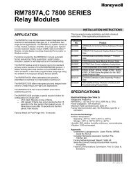
Series 008QT<br />
Spill-Resistant Pressure Vacuum Breaker<br />
Sizes: 3 ⁄8", 1 ⁄2", 3 ⁄4" and 1" (10, 15, 20, and 25mm)<br />
RP/IS-008QT<br />
Function: To protect the potable water supply against backfl<br />
ow from a non-potable source due to negative<br />
supply pressure<br />
Protection: Against back-siphonage backfl ow<br />
Installation Requirements<br />
1. Install a minimum of 1" above fl ood level of fi xture if factory<br />
deck mounted or not less than 6" if general plumbing<br />
fi eld application.<br />
2. Install bonnet side up and allow for accessibility for testing/<br />
service. Do not install in concealed locations or areas where<br />
water leakage due to normal wear of the internal parts can<br />
cause damage.<br />
3. Do not undersize supply or oversize the valve in relation<br />
to demand.<br />
4. Do not install where back-pressure can occur.<br />
5. Protect from freezing.<br />
Note: Use “L” suffi x for left-hand outlet.<br />
6. The installation of a strainer ahead of the backfl ow preventer<br />
is recommended to prevent fouling of the check assembly<br />
and resultant spillage from the valve during repressurizing.<br />
Recommended Service<br />
Test periodically as required by local jurisdictional authorities.<br />
Replace internal components every fi ve years.<br />
Pressure — Temperature<br />
Working Temperature: 33°F – 180°F (0.5ºC – 82ºC)<br />
Maximum Pressure: 150psi (10.3 bar)<br />
Minimum Pressure: 8psi (55 kPa)<br />
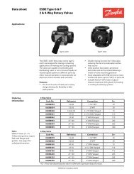
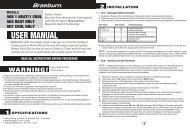
Installations:<br />
Min.<br />
of 1"<br />
008QT<br />
Test<br />
Cock<br />
Watts 008QT<br />
3<br />
⁄8", 1 ⁄2"<br />
Patent# 5125429<br />
Watts P50<br />
Pressure Reducing Valve<br />
Shutoffs<br />
Strainer<br />
3<br />
⁄4" Hose Adapter<br />
with strainer washer<br />
<strong>Supply</strong> Hose<br />
Solenoid Valve<br />
Watts 008QTS<br />
3<br />
⁄4", 1"<br />
Dispensing Inducers<br />
008QT<br />
▼<br />
6"<br />
Strainer<br />
recommended to<br />
prevent fouling of<br />
the check assembly<br />
and resultant spillage<br />
during start up.<br />
▼<br />
<strong>Supply</strong> Line<br />
Flood Rim Level<br />
008QT to be<br />
installed a<br />
minimum of 6"<br />
above the flood<br />
rim if applied for<br />
general plumbing<br />
applications.
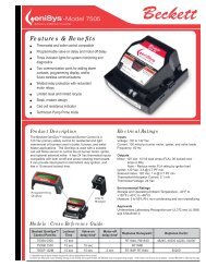
Test Procedure for Spill-Resistant<br />
Vacuum Breaker<br />
Note: For both of the following tests the test kit must be held at<br />
the same level as assembly being tested.<br />
A. Before starting test, all needle valves and bleed valves on test<br />
kit must be closed. B. Flush test cocks before test.<br />
Bleed<br />
Valve<br />
A<br />
Bleed<br />
Valve<br />
B<br />
Test No. 1 and 2<br />
TK99E Test Kit<br />
Test No. 1 Differential Test<br />
Test<br />
Cock<br />
008QT shown<br />
Requirement: Differential pressure across check must be<br />
1.0 psi or above<br />
Step 1 Remove two screws on top of hood then remove hood.<br />
Step 2 Install hose between test cock and connection “A” high<br />
side (red) of test kit.<br />
Step 3 Open test cock then open bleed valve “A” on top of test<br />
kit. Bleed air from hose then close bleed valve “A” on<br />
top of test kit.<br />
Step 4 Open needle valve “A” on high side (red) of test kit.<br />
Step 5 Close shutoff valve No. 2 then shut off valve No. 1<br />
on test assembly.<br />
Step 6 Slowly unscrew bleed screw on spill proof vacuum<br />
breaker body to relieve pressure down stream of check<br />
(about 3 tunes).<br />
Step 7 When dripping from bleed screw stops and psi needle<br />
on gauge stabilizes, record the differential pressure.<br />
Test No. 2 - Air Inlet - Vent Opening<br />
Requirement: Air inlet must start to open when supply pressure<br />
is 1.0psi or above. Air inlet must be fully open when supply pressure<br />
is atmospheric.<br />
Step 8 Slowly open needle valve “C” bypass (yellow) until psi<br />
gauge reads 1.0psi then close needle valve “C” bypass<br />
(yellow) holding pressure at 1.0psi.<br />
Step 9 Visually inspect that the vent on top is slightly open,<br />
about 1 /32". to pass test.<br />
Step 10 Open needle valve “C” bypass (yellow) fully until<br />
dripping from connection “C” stops.<br />
Step 11 Visually inspect that the vent is fully open to pass test.<br />
Step 12 Replace hood and two screws on top of assembly.<br />
Step 13 Restore valve to original working condition.<br />
Note: After test, all valves on test kit must be fully open and hose<br />
removed to prevent damage to test kit.<br />
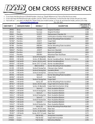
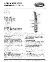
Service and Replacement Parts<br />
Internal parts can be removed, repaired or inspected without<br />
removing the valve from the piping.<br />
Reassembly:<br />
Install new retainer module assembly into valve body by aligning<br />
“U” shaped cutout in retainer with the valve outlet. The top of<br />
retainer must drop just below threads in the valve body. Reassemble<br />
remaining parts in reverse order.<br />
Caution: Spillage may occur if diaphragm is ruptured. Care<br />
must be taken not to damage parts during assembly.<br />
Disassembly:<br />
1. Shut off supply pressure and drain valve.<br />
2. Remove the two hood screws, remove hood.<br />
3. Unscrew the bonnet by turning counterclockwise.<br />
4. Lift retainer and check assembly from valve body. To assist with<br />
removal a small fl ow can be applied by “cracking” the inlet valve<br />
slightly. Alternately the test cock may be opened to break any<br />
suction caused by lifting internal assembly. Be sure to close test<br />
cock before pressurizing valve.<br />
Hood<br />
Bonnet<br />
O-ring<br />
Vent<br />
O-ring<br />
Body<br />
Retainer<br />
Check<br />
Assembly<br />
Hood Screws<br />
(2 Req'd)<br />
Vent<br />
Spring<br />
Test<br />
Cock<br />
Size: 3 ⁄8", 1 ⁄2"<br />
008QT Repair Kits<br />
Check Kits<br />
Air Bleed Screw<br />
Bleed O-ring<br />
(not shown<br />
Shutoff<br />
Valve Assy.<br />
(2 Req'd)<br />
O-ring<br />
Body<br />
Vent O-ring<br />
Retainer<br />
Hood<br />
Screw<br />
Hood<br />
Bonnet<br />
Vent<br />
Spring<br />
Check<br />
Assembly<br />
Test<br />
Cock<br />
Size: 3 ⁄4", 1"<br />
EDP NO. KIT NO. SIZES<br />
in. mm<br />
0887972 RK 008 T 3<br />
⁄8 - 1 ⁄2 10 -15<br />
0887974 RK 008 T 3<br />
⁄4 - 1 20-25<br />
Kit consists of: Check assembly O-ring, Spring, Vent O-ring, Bleed<br />
Screw O-ring and Retainer.<br />
Bonnet Kits<br />
EDP NO. KIT NO. SIZES<br />
in. mm<br />
0888012 RK 008 B 3<br />
⁄8 - 1 ⁄2 10-15<br />
0887973 RK 008 B 3<br />
⁄4 - 1 20-25<br />
Kit consists of: Bonnet, Bonnet O-ring and vent spring.<br />
Limited Warranty: Watts Regulator Co. (the “Company”) warrants each product to be free from defects in material and workmanship under normal usage for a period of one year from the date of<br />
original shipment. In the event of such defects within the warranty period, the Company will, at its option, replace or recondition the product without charge.<br />
THE WARRANTY SET FORTH HEREIN IS GIVEN EXPRESSLY AND IS THE ONLY WARRANTY GIVEN BY THE COMPANY WITH RESPECT TO THE PRODUCT. THE COMPANY MAKES NO OTHER<br />
WARRANTIES, EXPRESS OR IMPLIED. THE COMPANY HEREBY SPECIFICALLY DISCLAIMS ALL OTHER WARRANTIES, EXPRESS OR IMPLIED, INCLUDING BUT NOT LIMITED TO THE IMPLIED<br />
WARRANTIES OF MERCHANTABILITY AND FITNESS FOR A PARTICULAR PURPOSE.<br />
The remedy described in the first paragraph of this warranty shall constitute the sole and exclusive remedy for breach of warranty, and the Company shall not be responsible for any incidental, special<br />
or consequential damages, including without limitation, lost profits or the cost of repairing or replacing other property which is damaged if this product does not work properly, other costs resulting<br />
from labor charges, delays, vandalism, negligence, fouling caused by foreign material, damage from adverse water conditions, chemical, or any other circumstances over which the Company has<br />
no control. This warranty shall be invalidated by any abuse, misuse, misapplication, improper installation or improper maintenance or alteration of the product.<br />
Some States do not allow limitations on how long an implied warranty lasts, and some States do not allow the exclusion or limitation of incidental or consequential damages. Therefore the above<br />
limitations may not apply to you. This Limited Warranty gives you specific legal rights, and you may have other rights that vary from State to State. You should consult applicable state laws to<br />
determine your rights. SO FAR AS IS CONSISTENT WITH APPLICABLE STATE LAW, ANY IMPLIED WARRANTIES THAT MAY NOT BE DISCLAIMED, INCLUDING THE IMPLIED WARRANTIES OF<br />
MERCHANTABILITY AND FITNESS FOR A PARTICULAR PURPOSE, ARE LIMITED IN DURATION TO ONE YEAR FROM THE DATE OF ORIGINAL SHIPMENT.<br />
Backflow Prevention Products<br />
USA: 815 Chestnut St., No. Andover, MA 01845-6098; www.watts.com<br />
Canada: 5435 North Service Rd., Burlington, ONT. L7L 5H7; www.wattscanada.ca<br />
RP/IS-008QT 0829 EDP# 1915125 © Watts, 2008