
Create successful ePaper yourself
Turn your PDF publications into a flip-book with our unique Google optimized e-Paper software.
P/N 997-990120-1 Rev D<br />
FR&<strong>TECH</strong>-<br />
UT CONTROL BOARD<br />
62-24084-82<br />
THIS REPLACEMENT tS USED ON THE FOLLOWING FURNACES.I-]GRA, [-]GSA,[-]GTA,[-]GZC,<br />
[-]GZD 90+ Furnaces with Hot Surface lgnition. Also repairs Models [-]GDG,[-]GLH,[-]GPH,[-]GVH<br />
80+ Furnaces with Hot Surface lgnition. Please note that units built before "3294" may require the<br />
addition of a [ 62-24044-71 ] Flame Sensor Kit ordered separately.<br />
This MASTER REPLACEMENT PART replaces the following Control Boards:<br />
62-22694-01 62-22694-82 62-22737-08 62-24044-81 62-24084-02<br />
62-22694-02 62-22694-83 62-22737-10 62-24044-91 62-24084-71<br />
62-22694-03 62-22694-91 62-22737-87 62-24045-01 62-24084-82<br />
62-22694-11 62-22737-06 62-22737-88 62-24046-01 62-24084-91<br />
62-22694-12 62-22737-07 62-24044-01 62-24084-01 62-24084-92<br />
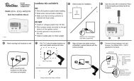
ln the event your system has DSI or Direct Spark lgnition, You must order part number 62-24140-02<br />
control board. Use the first 2 Letters of the units serial number to determine if itis HS/ - Hot Surface<br />
lgnition or DS/ - Direct Spark lgnition.<br />
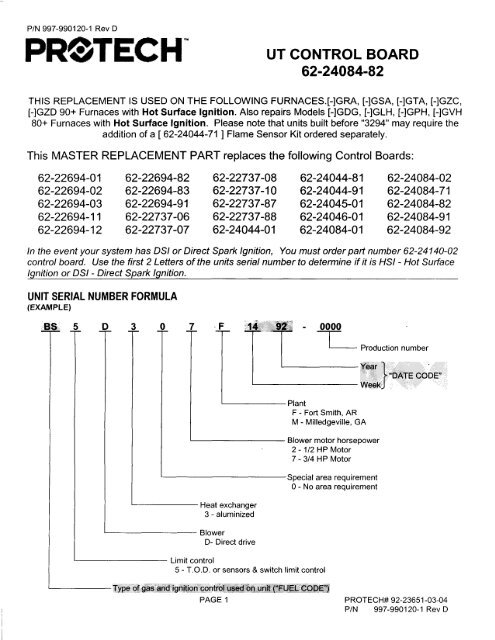
UNIT SERIAL NUMBER FORMULA<br />
(EXAMPLE)<br />
Productionumber<br />
"DATE CODH'<br />
Heat exchanger<br />
3 - aluminized<br />
Blower<br />
D- Direct drive<br />
Plant<br />
F - Fort Smith, AR<br />
M - Milledgeville, GA<br />
Limit control<br />
5 - T.O.D. or sensors & switch limit control<br />
Blower motor horsepower<br />
2 - 112 HP Motor<br />
7 - 314 HP Motor<br />
Special area requirement<br />
0 - No area requirement<br />
F Bc f.#cjaad1pjtjoh-:conffilL ,ffi lll;#nlff<br />
PAGE 1 P ROT EC H# 92-23651 -03-04<br />
P/N 997-990120-1 Rev D
MENU:<br />
The following MENU gives instructions to replace the control board on:<br />
1. Units which have NOf been converted to Remote Flame Sense.<br />
A. Normalnstallation - See pages 3, 6 and 7.<br />
B. Twinned Units<br />
- See pages 3,4,5,6, 7 and 8.<br />
C. Fossil Fuel Kits - See pages 3, 6,7 and 8-D.<br />
D. Twinned Units with Fossil Fuel Kits - See pages 3, 4, 5, 6,7 and 8-E.<br />
2. Units which have Remote Flame Sense installed at the Factory<br />
A. Normal lnstallation - See pages 3 and 8-A.<br />
B. Twinned Units - See pages 2, 3, 4 and 8-C.<br />
C. Fossil Fuel Kits - See pages 3 and 8-D.<br />
D. Twinned Units with Fossil Fuel Kits - See pages 3, 4, 5,6, 7 and 8-E.<br />
3. Units which have been converted to Remote Flame Sense by installing Remote Sense<br />
Kit62-24044-71<br />
A. Normal Installation - See pages 3 and B-8.<br />
B. Twinned Units - See pages 3, 4, 5, 6, 7 and 8-C.<br />
C. Fossil Fuel Kits - See pages 3 and 8-D.<br />
D. Twinned Units with Fossil Fuel Kits - See pages 3, 4, 5,6, 7 and 8-E.<br />
TABLE OF CONTENTS<br />
TitlePage ......1<br />
PAGE<br />
Serial NumberExplanation.... .......1<br />
Table of Contents 2<br />
Menu. 2<br />
lnstallationlnstructions .."... 3<br />
Twinning - Single Stage. 4<br />
Twinning - Two Stage 4<br />
Twinning - Wire Assembly. 5<br />
RemoteFlameSensorAdd-OnKit... ...." 6-7<br />
SPECIAL INSTRUCTIONS<br />
FactoryInstalled RemoteFlameSense<br />
Field Installed RemoteSense<br />
TwinnedUnits.<br />
Fossil Fuel Kits..<br />
Twinned Fossil Fuel Kits..<br />
....8-A<br />
.. '...8- B<br />
.....8-C<br />
'. '8- D<br />
..8-E<br />
PAGE 2
WARNING<br />
INSTRUCTIONS FOR NORMAL INSTALLATIONS<br />
TURN OFF ELECTRICAL POWER TO THE FURNACE BEFORE BEGINNING ANY<br />
MAINTENANCE. FAILURE TO DO SO CAN CAUSE ELECTRICAL SHOCK RESULTING IN<br />
SEVERE PERSONAL INJURY OR DEATH.<br />
1. REPLACING UT BOARD WITH UT BOARD<br />
A. No field modifications required.<br />
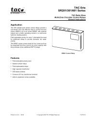
B. Set Blower Off Timing same as the old board or see sketch below for settings.<br />
2. REPLACING HONEYWELL BOARD WITH UT BOARD.<br />
A. Terminalocations are different but functionally the same. (This is also true for some UT boards).<br />
B. Set Blower Off Timing per sketch below. Replacement board is factory preset to 120 seconds.<br />
uTrG-920A<br />
ILOWIR OFF TINI}IGS<br />
NOTE: Install Boards Gently By<br />
Pressing In On Mounting Clip/Stand,<br />
Instead of Putting Pressure On The<br />
Body Of Control Board.<br />
The UT 1012-920 Control Boards have four "Quick-Connect" terminals for<br />
connecting the motor speed leads. These are.<br />
-t:^ ^<br />
a4ffi> 0,r,,-ri<br />
I \/- J lnnl<br />
' L.,t t-,!q<br />
N0Tt, SVITCHIS 3 & 4 ARt USID<br />
fOR TV]NNIN6 APPLICA]IONS.<br />
OFF TIMER<br />
)<br />
0<br />
z<br />
SWTCH 1 SWTCH 2<br />
90 !tt, DFr 0N<br />
120 !EC !FF Dtr<br />
1r,0 stc,<br />
trF<br />
1BO SIC,<br />
IN<br />
1. FAN - Motor runs on this speed when the thermostat is in the continuous "FAN ON" oosition.<br />
2. COOL - Connecto desired cooling speed.<br />
3. HEAT - Connecto desired heating speed.<br />
4. HEAT/COOL - Connect desired speed when heating and cooling speed are the same<br />
IMPORTANT: DO NOT CONNECT ANY MOTOR SPEEDS TO,'HEAT', ANDIOR'COOL,, IF YOU IJSE THE<br />
,,<br />
H EAT I CO O L" TER MI N AL.<br />
5. lf heating and continuous fan speed are the same, connect a "piggy-back" jumper across "FAN" and "HEAT"<br />
L-l\<br />
-r<br />
PIGGYBACK<br />
3%'<br />
PAGE 3
INSTRUGTIONS USING TWINNED FURNACES<br />
(SINGLE STAGE HEAT)<br />
1. REPLACING HONEYWELL BOARD WITH UT BOARD<br />
A. When furnaces are twinned, they "MUST" use the same control boards. Therefore, replace both<br />
boards with UT 62-24084-82.<br />
B. Remove (2) wires from "XMIT" to "RCV" and "RCV" to "XMIT" on H/VV boards.<br />
C. Remove wire from "GND" to "GND" on Honeywell boards.<br />
D. Connect low voltage wire from "C" to "C" on UT boards.<br />
E. Connect low voltage wire from "TWIN" terminal on UT board to "TWIN" terminal on (2nd) UT board.<br />
F. Connect low voltage wire from "W" terminal on UT board to "W" terminal on (2nd) UT board.<br />
G. Reference wiring diagram on page 5 for remaining connections. NOTE: Terminals W, Y, G, R, C on UT<br />
boards are in different sequence on H/VV boards.<br />
H. Adjust Heat Anticipator Current for 0.2 amps, then set Blower Off Timings per 1B or 28 on page 3.<br />
L Set twining DIP switches 3 and 4 to "TWlN" and "'1st" on both controls.<br />
INSTRUCTIONS USING TWINNED FURNACES<br />
(TWO STAGE HEAT)<br />
1. REPLACING H^|/ BOARD WITH UT BOARD<br />
A. When furnaces are twinned, they'MUST" use the same control boards. Therefore, replace both<br />
boards with UT 62-24084-82.<br />
B. Remove (2) wires from "XMIT" to "RCV" and "RCV" to "XMIT" on HAIV boards.<br />
C. Remove wire from "GND" to "GND" on Honeywell boards.<br />
D. Connect low voltage wire from "C" to "C" on UT boards.<br />
E. Connect low voltage wire from "TWIN" terminal on UT board to "TWIN" terminal on (2nd) UT board.<br />
F. Connect "Wl" of thermostato "W" of UT Control Board connected to thermostat.<br />
G. Connect "W2" of thermostato "W" of (2nd) UT Control board.<br />
H. Reference wiring diagram on page 5 for remaining connections. NOTE: Terminals W, Y, G, R, C on UT<br />
boards are in different sequence on H/W boards.<br />
l. Adjust heat anticipator current for 0.1 amps on each stage of heating, then set Blower Off Timinqs per<br />
'1B or 28 on paqe 3.<br />
J. Set twining DIP switches 3 and 4 to "TWlN" and "1st" on 1st control, and "TWlN" and "2nd" on 2nd<br />
control.<br />
PAGE 4
!l ll rtr Ll ll ril<br />
(SINGLE<br />
IVINY G V R C O TVINY G V R C<br />
r^<br />
H<br />
RG<br />
!v<br />
V(I<br />
c0uLlNG<br />
CONTACTER<br />
I rmRI<br />
tl<br />
or{ p-1 lrsr lnonf<br />
nrnrl f l l:rnrs t-f<br />
ttt I<br />
| | l|_rl<br />
ll"t<br />
ffzh<br />
O<br />
(TV! S<br />
TVINY 6 V R C<br />
TVINY G V R C<br />
Tvt<br />
H<br />
E<br />
R<br />
M<br />
0<br />
s<br />
T<br />
AR<br />
T<br />
COELING<br />
CDNTACTOR<br />
CAUTION MUST BE USED TO FOLLOW ALL INSTRUCTIONS. UNIT'S OPERATION MUST BE<br />
CHECKED FOR PROPER PERFORMACE AFTER THE REPAIR IS MADE. IN THE EVENT THERE ARE<br />
ANY QUESTIONS, CONTACT YOUR LOCAL DISTRIBUTOR OR SERVICE REPRESENTATIVE.<br />
PAGE 5
WARNING<br />
ADDING REMOTE FLAME SENSOR<br />
62-24044-71 (ORD E RE D S E PARATE Ly)<br />
TURN OFF ELECTRICAL POWER TO THE FURNACE BEFORE BEGINNING ANY<br />
MAINTENANCE. FAILURE TO DO SO CAN CAUSE ELECTRICAL SHOGK RESULTING IN<br />
SEVERE PERSONAL INJURY OR DEATH.<br />
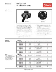
1. Remove all necessary covers and panels to gain access to the burners.<br />
NOTE: THIS KIT IS DESIGNED TO BE INSTALLED WITH BURNERS AND GAS ASSEMBLY IN PLACE.<br />
2. f he 34" Low Profile furnace uses "inshot" bracket (AE-57974-Ol ) with two holes on the front, see bracket below.<br />
-..-...:<br />
t (..r<br />
F I.. ]PT<br />
(<br />
I<br />
l<br />
?<br />
4.<br />
q<br />
The sensor bracket mounts to the burner as shown in Figure 2. Position the bracket on the appropriate side of the<br />
burner support and align the two holes. NOTE: The flat flange on the bracket must be AWAY FROM THE BURNERS.<br />
lnsert the screws through the holes in the burner bracket and tighten with a ratchet wrench and 114 socket. See<br />
Figure 2.<br />
Inserthe sensor (62-23543-01) through the hole in the bracket. Use a 114" nu| driver to anchor the sensor with one<br />
of the sheet metal screws provided. The sensor rod should pa$s diagonally in front of the burner, a$ $hown. See<br />
Figure 3"<br />
IMPORTATNT: DO NOT ALLOW THE SENSOR ROD TO TOUCH ANY FURNACE COMPONENT.<br />
BllPNtP<br />
?,1? Aa( aI<br />
"t)??tP1<br />
P,?tJ,(f I<br />
'/<br />
B!PN[P<br />
liiltf<br />
a9<br />
o<br />
o<br />
".2'<br />
t-..r-<br />
f I GI]PT ?<br />
? A'.a.alrtva1<br />
PAGE 6
6.<br />
7.<br />
8.<br />
Inserl the 19' orange wire in the comer socket between the red and blue wire. The quick connect end of this wire<br />
goes to the rcmote flame sansor. (See diagram belou)<br />
Insert the ends of the 28'orange wire in the comer between red and blue wire of both plugs. (See diagram below.)<br />
Stick the new wiring diagram label over the old wiring diagram located on the inside of the control box cover.<br />
I]RANGt VIRE<br />
MUST BE INSTALLTD HIRI<br />
RED WIRE<br />
BLUE VIRE<br />
I/4'FEMALE O,C,(INSULATED)<br />
PURPLE<br />
VIRE<br />
19', WIRt<br />
9-P]N FII4ALE PLUG<br />
BLOVER SHELF<br />
ORANGT VIRT MUST BI INSTALLID HIRI<br />
BLUt VIRf<br />
RID V]RE<br />
ORANGI . V]RI MUSI<br />
BLUEVIRE<br />
?8' VlRt---<br />
INSTALLID HTRE<br />
(PIN_7)<br />
9-PIN t'tALt PLUG<br />
\<br />
\<br />
\<br />
"\<br />
t-ffi<br />
-<br />
]*<br />
INTEGRATTD FURNACI<br />
Ct]NTRDL<br />
i'.. #Fl.lT<br />
FIGURT 4, TYPICAL UPFL!V FURNACT<br />
PAGE 7
-<br />
SPEGIAL INSTRUCTIONS<br />
A. REMOTE SENSOR INSTALLED AT THE FACTORY:<br />
1. Disconnect the wire to the Remote Sensor.<br />
2. Use Wire Ties to secure the old Remote Sensor lead.<br />
3. Install the new Remote Sensor wiring as outlined on page 7, Steps 6 through 9.<br />
B. REMOTE SENSOR ADDED BY KIT 62-24044-71<br />
1. Disconnect the wire from the Remote Sensor and from the Splice at HSI power supply wire.<br />
2. Leave the insulated Splice in place on HSI power supply wire.<br />
3. Discard the old Remote Sensor wire.<br />
4. Install the new Remote Sensor wiring as outlined on page 7, Steps 6 through 9.<br />
C. TWINNED UNITS:<br />
1. Replace both control boards as outlined on page 3 and 4.<br />
2. Interconnect the two control boards as shown on page 5.<br />
3. Make Thermostat connections to the "Master" control as shown on page 5.<br />
D. FOSSIL FUEL KITS:<br />
1. Control is compatible with Fossil Fuel Kits RXPF-EO1, RXPF-FO1, and RXPF-FO2<br />
2. Replace the control board as outlined on page 3.<br />
3. Wire the Thermostat connections in accordance with the Heat Pump System Wiring Schematics.<br />
Terminal locations on the control may be different, but are functionally the same. (lf desired, an<br />
RXPF-CO1 or RXPF-E01 may be field converted to an RXPF-FO1. The system components are the<br />
same, but the wiring is different.)<br />
References for Fossil Fuel Kit Information:<br />
92-21779-08 Typical Remote Heat Pump System Wiring Schematics<br />
92-20871-23 Installation Instructionsfor Fossil Fuel Kits RXPF-F01 and RXPF-FO2<br />
92-20871-16 lnstallation Instructions for Fossil Fuel Kits RXPF-C01. RXPF-DO2 and RXPF-EO1<br />
E. TWINNED UNITS WITH FOSSILE FUEL KITS:<br />
1. Replace both control boards as outlined on page 3 and 4.<br />
2. Interconnect the two control boards as shown on page 5.<br />
3. Wire the Thermostat connections in accordance with the Heat Pump System Wiring Schematics.<br />
Terminalocations on the control may be different, but are functionally the same. See Fossil Fuel Kit<br />
information above. Make the Thermostat connections to the "Master" control as shown on page 5.<br />
PAGE B