P89V51RB2/RC2/RD2 8-bit 80C51 5 V low power 16/32 ... - NetMedia
P89V51RB2/RC2/RD2 8-bit 80C51 5 V low power 16/32 ... - NetMedia
P89V51RB2/RC2/RD2 8-bit 80C51 5 V low power 16/32 ... - NetMedia

You also want an ePaper? Increase the reach of your titles
YUMPU automatically turns print PDFs into web optimized ePapers that Google loves.
<strong>P89V51RB2</strong>/<strong>RC2</strong>/<strong>RD2</strong><br />
8-<strong>bit</strong> <strong>80C51</strong> 5 V <strong>low</strong> <strong>power</strong> <strong>16</strong>/<strong>32</strong>/64 kB flash microcontroller<br />
with 1 kB RAM<br />
Rev. 04 — 1 May 2007<br />
Product data sheet<br />
1. General description<br />
2. Features<br />
The <strong>P89V51RB2</strong>/<strong>RC2</strong>/<strong>RD2</strong> are <strong>80C51</strong> microcontrollers with <strong>16</strong>/<strong>32</strong>/64 kB flash and<br />
1024 B of data RAM.<br />
A key feature of the <strong>P89V51RB2</strong>/<strong>RC2</strong>/<strong>RD2</strong> is its X2 mode option. The design engineer<br />
can choose to run the application with the conventional <strong>80C51</strong> clock rate (12 clocks per<br />
machine cycle) or select the X2 mode (six clocks per machine cycle) to achieve twice the<br />
throughput at the same clock frequency. Another way to benefit from this feature is to keep<br />
the same performance by reducing the clock frequency by half, thus dramatically reducing<br />
the EMI.<br />
The flash program memory supports both parallel programming and in serial ISP. Parallel<br />
programming mode offers gang-programming at high speed, reducing programming costs<br />
and time to market. ISP al<strong>low</strong>s a device to be reprogrammed in the end product under<br />
software control. The capability to field/update the application firmware makes a wide<br />
range of applications possible.<br />
The <strong>P89V51RB2</strong>/<strong>RC2</strong>/<strong>RD2</strong> is also capable of IAP, al<strong>low</strong>ing the flash program memory to<br />
be reconfigured even while the application is running.<br />
■ <strong>80C51</strong> CPU<br />
■ 5 V operating voltage from 0 MHz to 40 MHz<br />
■ <strong>16</strong>/<strong>32</strong>/64 kB of on-chip flash user code memory with ISP and IAP<br />
■ Supports 12-clock (default) or 6-clock mode selection via software or ISP<br />
■ SPI and enhanced UART<br />
■ PCA with PWM and capture/compare functions<br />
■ Four 8-<strong>bit</strong> I/O ports with three high-current port 1 pins (<strong>16</strong> mA each)<br />
■ Three <strong>16</strong>-<strong>bit</strong> timers/counters<br />
■ Programmable watchdog timer<br />
■ Eight interrupt sources with four priority levels<br />
■ Second DPTR register<br />
■ Low EMI mode (ALE inhi<strong>bit</strong>)<br />
■ TTL- and CMOS-compatible logic levels
NXP Semiconductors<br />
<strong>P89V51RB2</strong>/<strong>RC2</strong>/<strong>RD2</strong><br />
8-<strong>bit</strong> microcontrollers with <strong>80C51</strong> core<br />
3. Ordering information<br />
■ Brownout detection<br />
■ Low <strong>power</strong> modes<br />
◆ Power-down mode with external interrupt wake-up<br />
◆ Idle mode<br />
■ DIP40, PLCC44 and TQFP44 packages<br />
Table 1. Ordering information<br />
Type number Package<br />
Name Description Version<br />
<strong>P89V51RB2</strong>FA PLCC44 plastic leaded chip carrier; 44 leads SOT187-2<br />
<strong>P89V51RB2</strong>FN DIP40 plastic dual in-line package; 40 leads (600 mil) SOT129-1<br />
<strong>P89V51RB2</strong>BBC TQFP44 plastic thin quad flat package; 44 leads; body 10 × 10 × 1.0 mm SOT376-1<br />
P89V51<strong>RC2</strong>FA PLCC44 plastic leaded chip carrier; 44 leads SOT187-2<br />
P89V51<strong>RC2</strong>FBC TQFP44 plastic thin quad flat package; 44 leads; body 10 × 10 × 1.0 mm SOT376-1<br />
P89V51<strong>RC2</strong>FN DIP40 plastic dual in-line package; 40 leads (600 mil) SOT129-1<br />
P89V51<strong>RD2</strong>FA PLCC44 plastic leaded chip carrier; 44 leads SOT187-2<br />
P89V51<strong>RD2</strong>FBC TQFP44 plastic thin quad flat package; 44 leads; body 10 × 10 × 1.0 mm SOT376-1<br />
P89V51<strong>RD2</strong>BN DIP40 plastic dual in-line package; 40 leads (600 mil) SOT129-1<br />
P89V51<strong>RD2</strong>FN DIP40 plastic dual in-line package; 40 leads (600 mil) SOT129-1<br />
3.1 Ordering options<br />
Table 2. Ordering options<br />
Type number Flash memory Temperature range Frequency<br />
<strong>P89V51RB2</strong>FA <strong>16</strong> kB −40 °C to+85°C 0 MHz to 40 MHz<br />
<strong>P89V51RB2</strong>FN <strong>16</strong> kB −40 °C to+85°C<br />
<strong>P89V51RB2</strong>BBC <strong>16</strong> kB 0 °C to+70°C<br />
P89V51<strong>RC2</strong>FA <strong>32</strong> kB −40 °C to+85°C<br />
P89V51<strong>RC2</strong>FBC <strong>32</strong> kB −40 °C to+85°C<br />
P89V51<strong>RC2</strong>FN <strong>32</strong> kB −40 °C to+85°C<br />
P89V51<strong>RD2</strong>FA 64 kB −40 °C to+85°C<br />
P89V51<strong>RD2</strong>FBC 64 kB −40 °C to+85°C<br />
P89V51<strong>RD2</strong>BN 64 kB 0 °C to+70°C<br />
P89V51<strong>RD2</strong>FN 64 kB −40 °C to+85°C<br />
<strong>P89V51RB2</strong>_<strong>RC2</strong>_<strong>RD2</strong>_4<br />
© NXP B.V. 2007. All rights reserved.<br />
Product data sheet Rev. 04 — 1 May 2007 2 of 80
NXP Semiconductors<br />
<strong>P89V51RB2</strong>/<strong>RC2</strong>/<strong>RD2</strong><br />
8-<strong>bit</strong> microcontrollers with <strong>80C51</strong> core<br />
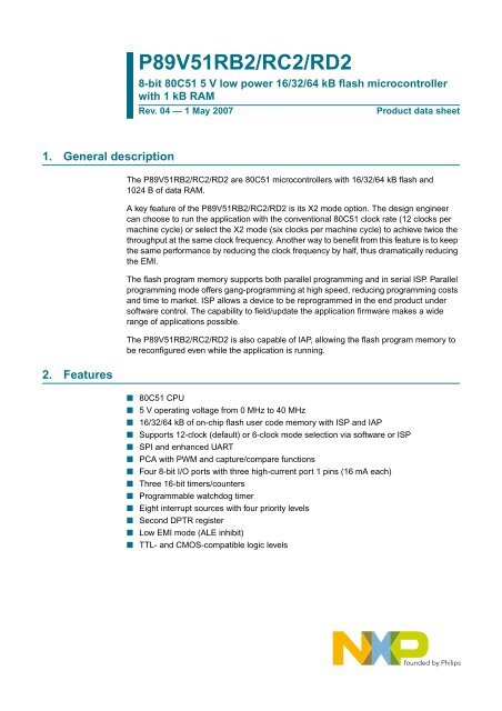
4. Block diagram<br />
<strong>P89V51RB2</strong>/<strong>RC2</strong>/<strong>RD2</strong><br />
HIGH PERFORMANCE<br />
<strong>80C51</strong> CPU<br />
<strong>16</strong>/<strong>32</strong>/64 kB<br />
CODE FLASH<br />
1 kB<br />
DATA RAM<br />
internal<br />
bus<br />
UART<br />
TIMER 0<br />
TIMER 1<br />
TXD<br />
RXD<br />
T0<br />
T1<br />
P3[7:0]<br />
PORT 3<br />
TIMER 2<br />
T2<br />
T2EX<br />
P2[7:0]<br />
PORT 2<br />
SPI<br />
SPICLK<br />
MOSI<br />
MISO<br />
SS<br />
P1[7:0]<br />
PORT 1<br />
PCA<br />
PROGRAMMABLE<br />
COUNTER ARRAY<br />
CEX[4:0]<br />
P0[7:0]<br />
PORT 0<br />
WATCHDOG TIMER<br />
CRYSTAL<br />
OR<br />
RESONATOR<br />
XTAL1<br />
XTAL2<br />
OSCILLATOR<br />
002aac772<br />
Fig 1.<br />
Block diagram<br />
<strong>P89V51RB2</strong>_<strong>RC2</strong>_<strong>RD2</strong>_4<br />
© NXP B.V. 2007. All rights reserved.<br />
Product data sheet Rev. 04 — 1 May 2007 3 of 80
NXP Semiconductors<br />
<strong>P89V51RB2</strong>/<strong>RC2</strong>/<strong>RD2</strong><br />
8-<strong>bit</strong> microcontrollers with <strong>80C51</strong> core<br />
5. Pinning information<br />
5.1 Pinning<br />
P1.5/MOSI/CEX2 7<br />
P1.6/MISO/CEX3 8<br />
P1.7/SCK/CEX4 9<br />
RST 10<br />
P3.0/RXD 11<br />
n.c. 12<br />
P3.1/TXD 13<br />
P3.2/INT0 14<br />
P3.3/INT1 15<br />
P3.4/T0 <strong>16</strong><br />
P3.5/T1 17<br />
P3.6/WR P3.7/RD 18<br />
19<br />
6 5 P1.4/SS/CEX1<br />
P1.3/CEX0<br />
XTAL2 20<br />
4 P1.2/ECI<br />
XTAL1 21<br />
3 P1.1/T2EX<br />
VSS 22<br />
2 P1.0/T2<br />
n.c. 23<br />
1 n.c.<br />
P2.0/A8 24<br />
44 VDD<br />
P2.1/A9 25<br />
43 P0.0/AD0<br />
P2.2/A10 26<br />
42 P0.1/AD1<br />
P2.3/A11 27<br />
41 P0.2/AD2<br />
P2.4/A12 28<br />
40 P0.3/AD3<br />
<strong>P89V51RB2</strong>FA<br />
P89V51<strong>RC2</strong>FA<br />
P89V51<strong>RD2</strong>FA<br />
39 P0.4/AD4<br />
38 P0.5/AD5<br />
37 P0.6/AD6<br />
36 P0.7/AD7<br />
35 EA<br />
34 n.c.<br />
33 ALE/PROG<br />
<strong>32</strong> PSEN<br />
31 P2.7/A15<br />
30 P2.6/A14<br />
29 P2.5/A13<br />
002aaa810<br />
Fig 2.<br />
PLCC44 pin configuration<br />
<strong>P89V51RB2</strong>_<strong>RC2</strong>_<strong>RD2</strong>_4<br />
© NXP B.V. 2007. All rights reserved.<br />
Product data sheet Rev. 04 — 1 May 2007 4 of 80
NXP Semiconductors<br />
<strong>P89V51RB2</strong>/<strong>RC2</strong>/<strong>RD2</strong><br />
8-<strong>bit</strong> microcontrollers with <strong>80C51</strong> core<br />
P1.0/T2<br />
1<br />
40<br />
V DD<br />
P1.1/T2EX<br />
2<br />
39<br />
P0.0/AD0<br />
P1.2/ECI<br />
3<br />
38<br />
P0.1/AD1<br />
P1.3/CEX0<br />
4<br />
37<br />
P0.2/AD2<br />
P1.4/SS/CEX1<br />
5<br />
36<br />
P0.3/AD3<br />
P1.5/MOSI/CEX2<br />
6<br />
35<br />
P0.4/AD4<br />
P1.6/MISO/CEX3<br />
7<br />
34<br />
P0.5/AD5<br />
P1.7/SCK/CEX4<br />
RST<br />
P3.0/RXD<br />
P3.1/TXD<br />
P3.2/INT0<br />
8<br />
9<br />
10<br />
11<br />
12<br />
<strong>P89V51RB2</strong>FN<br />
P89V51<strong>RC2</strong>FN<br />
P89V51<strong>RD2</strong>BN<br />
P89V51<strong>RD2</strong>FN<br />
33<br />
<strong>32</strong><br />
31<br />
30<br />
29<br />
P0.6/AD6<br />
P0.7/AD7<br />
EA<br />
ALE/PROG<br />
PSEN<br />
P3.3/INT1<br />
13<br />
28<br />
P2.7/A15<br />
P3.4/T0<br />
14<br />
27<br />
P2.6/A14<br />
P3.5/T1<br />
15<br />
26<br />
P2.5/A13<br />
P3.6/WR<br />
<strong>16</strong><br />
25<br />
P2.4/A12<br />
P3.7/RD<br />
17<br />
24<br />
P2.3/A11<br />
XTAL2<br />
18<br />
23<br />
P2.2/A10<br />
XTAL1<br />
19<br />
22<br />
P2.1/A9<br />
V SS<br />
20<br />
21<br />
P2.0/A8<br />
002aaa811<br />
Fig 3.<br />
DIP40 pin configuration<br />
P1.5/MOSI/CEX2<br />
P1.6/MISO/CEX3<br />
P1.7/SCK/CEX4<br />
RST<br />
P3.0/RXD<br />
n.c.<br />
P3.1/TXD<br />
P3.2/INT0<br />
P3.3/INT1<br />
P3.4/T0<br />
P3.5/T1<br />
1<br />
2<br />
3<br />
4<br />
5<br />
6<br />
7<br />
8<br />
9<br />
10<br />
11<br />
P3.6/WR 12<br />
44 P1.4/SS/CEX1<br />
P3.7/RD 13<br />
43 P1.3/CEX0<br />
XTAL2 14<br />
42 P1.2/ECI<br />
XTAL1 15<br />
41 P1.1/T2EX<br />
VSS <strong>16</strong><br />
40 P1.0/T2<br />
n.c. 17<br />
39 n.c.<br />
P2.0/A8 18<br />
38 VDD<br />
P2.1/A9 19<br />
37 P0.0/AD0<br />
P2.2/A10 20<br />
36 P0.1/AD1<br />
<strong>P89V51RB2</strong>BBC<br />
P89V51<strong>RC2</strong>FBC<br />
P89V51<strong>RD2</strong>FBC<br />
P2.3/A11 21<br />
35 P0.2/AD2<br />
P2.4/A12 22<br />
34 P0.3/AD3<br />
33 P0.4/AD4<br />
<strong>32</strong> P0.5/AD5<br />
31 P0.6/AD6<br />
30 P0.7/AD7<br />
29 EA<br />
28 n.c.<br />
27 ALE/PROG<br />
26 PSEN<br />
25 P2.7/A15<br />
24 P2.6/A14<br />
23 P2.5/A13<br />
002aaa812<br />
Fig 4.<br />
TQFP44 pin configuration<br />
<strong>P89V51RB2</strong>_<strong>RC2</strong>_<strong>RD2</strong>_4<br />
© NXP B.V. 2007. All rights reserved.<br />
Product data sheet Rev. 04 — 1 May 2007 5 of 80
NXP Semiconductors<br />
<strong>P89V51RB2</strong>/<strong>RC2</strong>/<strong>RD2</strong><br />
8-<strong>bit</strong> microcontrollers with <strong>80C51</strong> core<br />
Table 3.<br />
5.2 Pin description<br />
<strong>P89V51RB2</strong>/<strong>RC2</strong>/<strong>RD2</strong> pin description<br />
Symbol Pin Type Description<br />
DIP40 TQFP44 PLCC44<br />
P0.0 to P0.7 I/O Port 0: Port 0 is an 8-<strong>bit</strong> open drain bidirectional I/O port.<br />
Port 0 pins that have ‘1’s written to them float, and in this<br />
state can be used as high-impedance inputs. Port 0 is also<br />
the multiplexed <strong>low</strong>-order address and data bus during<br />
accesses to external code and data memory. In this<br />
application, it uses strong internal pull-ups when<br />
transitioning to ‘1’s. Port 0 also receives the code bytes<br />
during the external host mode programming, and outputs<br />
the code bytes during the external host mode verification.<br />
External pull-ups are required during program verification<br />
or as a general purpose I/O port.<br />
P0.0/AD0 39 37 43 I/O P0.0 — Port 0 <strong>bit</strong> 0.<br />
I/O AD0 — Address/data <strong>bit</strong> 0.<br />
P0.1/AD1 38 36 42 I/O P0.1 — Port 0 <strong>bit</strong> 1.<br />
I/O AD1 — Address/data <strong>bit</strong> 1.<br />
P0.2/AD2 37 35 41 I/O P0.2 — Port 0 <strong>bit</strong> 2.<br />
I/O AD2 — Address/data <strong>bit</strong> 2.<br />
P0.3/AD3 36 34 40 I/O P0.3 — Port 0 <strong>bit</strong> 3.<br />
I/O AD3 — Address/data <strong>bit</strong> 3.<br />
P0.4/AD4 35 33 39 I/O P0.4 — Port 0 <strong>bit</strong> 4.<br />
I/O AD4 — Address/data <strong>bit</strong> 4.<br />
P0.5/AD5 34 <strong>32</strong> 38 I/O P0.5 — Port 0 <strong>bit</strong> 5.<br />
I/O AD5 — Address/data <strong>bit</strong> 5.<br />
P0.6/AD6 33 31 37 I/O P0.6 — Port 0 <strong>bit</strong> 6.<br />
I/O AD6 — Address/data <strong>bit</strong> 6.<br />
P0.7/AD7 <strong>32</strong> 30 36 I/O P0.7 — Port 0 <strong>bit</strong> 7.<br />
I/O AD7 — Address/data <strong>bit</strong> 7.<br />
P1.0 to P1.7 I/O with<br />
internal<br />
pull-up<br />
Port 1: Port 1 is an 8-<strong>bit</strong> bidirectional I/O port with internal<br />
pull-ups. The Port 1 pins are pulled high by the internal<br />
pull-ups when ‘1’s are written to them and can be used as<br />
inputs in this state. As inputs, Port 1 pins that are<br />
externally pulled LOW will source current (I IL ) because of<br />
the internal pull-ups. P1.5, P1.6, P1.7 have high current<br />
drive of <strong>16</strong> mA. Port 1 also receives the <strong>low</strong>-order address<br />
bytes during the external host mode programming and<br />
verification.<br />
P1.0/T2 1 40 2 I/O P1.0 — Port 1 <strong>bit</strong> 0.<br />
I/O T2 — External count input to Timer/counter 2 or Clock-out<br />
from Timer/counter 2.<br />
P1.1/T2EX 2 41 3 I/O P1.1 — Port 1 <strong>bit</strong> 1.<br />
I<br />
T2EX: Timer/counter 2 capture/reload trigger and direction<br />
control.<br />
<strong>P89V51RB2</strong>_<strong>RC2</strong>_<strong>RD2</strong>_4<br />
© NXP B.V. 2007. All rights reserved.<br />
Product data sheet Rev. 04 — 1 May 2007 6 of 80
NXP Semiconductors<br />
<strong>P89V51RB2</strong>/<strong>RC2</strong>/<strong>RD2</strong><br />
8-<strong>bit</strong> microcontrollers with <strong>80C51</strong> core<br />
Table 3.<br />
<strong>P89V51RB2</strong>/<strong>RC2</strong>/<strong>RD2</strong> pin description …continued<br />
Symbol Pin Type Description<br />
DIP40 TQFP44 PLCC44<br />
P1.2/ECI 3 42 4 I/O P1.2 — Port 1 <strong>bit</strong> 2.<br />
I<br />
ECI — External clock input. This signal is the external<br />
clock input for the PCA.<br />
P1.3/CEX0 4 43 5 I/O P1.3 — Port 1 <strong>bit</strong> 3.<br />
I/O CEX0 — Capture/compare external I/O for PCA Module 0.<br />
Each capture/compare module connects to a Port 1 pin for<br />
external I/O. When not used by the PCA, this pin can<br />
handle standard I/O.<br />
P1.4/SS/CEX1 5 44 6 I/O P1.4 — Port 1 <strong>bit</strong> 4.<br />
I<br />
SS — Slave port select input for SPI.<br />
I/O CEX1 — Capture/compare external I/O for PCA Module 1.<br />
P1.5/MOSI/ 6 1 7 I/O P1.5 — Port 1 <strong>bit</strong> 5.<br />
CEX2<br />
I/O MOSI — Master Output Slave Input for SPI.<br />
I/O CEX2 — Capture/compare external I/O for PCA Module 2.<br />
P1.6/MISO/ 7 2 8 I/O P1.6 — Port 1 <strong>bit</strong> 6.<br />
CEX3<br />
I/O MISO — Master Input Slave Output for SPI.<br />
I/O CEX3 — Capture/compare external I/O for PCA Module 3.<br />
P1.7/SCK/ 8 3 9 I/O P1.7 — Port 1 <strong>bit</strong> 7.<br />
CEX4<br />
I/O SCK — Master Output Slave Input for SPI.<br />
I/O CEX4 — Capture/compare external I/O for PCA Module 4.<br />
P2.0 to P2.7 I/O with<br />
internal<br />
pull-up<br />
P2.0/A8 21 18 24 I/O P2.0 — Port 2 <strong>bit</strong> 0.<br />
O A8 — Address <strong>bit</strong> 8.<br />
P2.1/A9 22 19 25 I/O P2.1 — Port 2 <strong>bit</strong> 1.<br />
O A9 — Address <strong>bit</strong> 9.<br />
P2.2/A10 23 20 26 I/O P2.2 — Port 2 <strong>bit</strong> 2.<br />
O A10 — Address <strong>bit</strong> 10.<br />
P2.3/A11 24 21 27 I/O P2.3 — Port 2 <strong>bit</strong> 3.<br />
O A11 — Address <strong>bit</strong> 11.<br />
P2.4/A12 25 22 28 I/O P2.4 — Port 2 <strong>bit</strong> 4.<br />
O A12 — Address <strong>bit</strong> 12.<br />
Port 2: Port 2 is an 8-<strong>bit</strong> bidirectional I/O port with internal<br />
pull-ups. Port 2 pins are pulled HIGH by the internal<br />
pull-ups when ‘1’s are written to them and can be used as<br />
inputs in this state. As inputs, Port 2 pins that are<br />
externally pulled LOW will source current (I IL ) because of<br />
the internal pull-ups. Port 2 sends the high-order address<br />
byte during fetches from external program memory and<br />
during accesses to external Data Memory that use <strong>16</strong>-<strong>bit</strong><br />
address (MOVX@DPTR). In this application, it uses strong<br />
internal pull-ups when transitioning to ‘1’s. Port 2 also<br />
receives some control signals and a partial of high-order<br />
address <strong>bit</strong>s during the external host mode programming<br />
and verification.<br />
<strong>P89V51RB2</strong>_<strong>RC2</strong>_<strong>RD2</strong>_4<br />
© NXP B.V. 2007. All rights reserved.<br />
Product data sheet Rev. 04 — 1 May 2007 7 of 80
NXP Semiconductors<br />
<strong>P89V51RB2</strong>/<strong>RC2</strong>/<strong>RD2</strong><br />
8-<strong>bit</strong> microcontrollers with <strong>80C51</strong> core<br />
Table 3.<br />
<strong>P89V51RB2</strong>/<strong>RC2</strong>/<strong>RD2</strong> pin description …continued<br />
Symbol Pin Type Description<br />
DIP40 TQFP44 PLCC44<br />
P2.5/A13 26 23 29 I/O P2.5 — Port 2 <strong>bit</strong> 5.<br />
O A13 — Address <strong>bit</strong> 13.<br />
P2.6/A14 27 24 30 I/O P2.6 — Port 2 <strong>bit</strong> 6.<br />
O A14 — Address <strong>bit</strong> 14.<br />
P2.7/A15 28 25 31 I/O P2.7 — Port 2 <strong>bit</strong> 7.<br />
O A15 — Address <strong>bit</strong> 15.<br />
P3.0 to P3.7 I/O with<br />
internal<br />
pull-up<br />
Port 3: Port 3 is an 8-<strong>bit</strong> bidirectional I/O port with internal<br />
pull-ups. Port 3 pins are pulled HIGH by the internal<br />
pull-ups when ‘1’s are written to them and can be used as<br />
inputs in this state. As inputs, Port 3 pins that are<br />
externally pulled LOW will source current (I IL ) because of<br />
the internal pull-ups. Port 3 also receives some control<br />
signals and a partial of high-order address <strong>bit</strong>s during the<br />
external host mode programming and verification.<br />
P3.0/RXD 10 5 11 I P3.0 — Port 3 <strong>bit</strong> 0.<br />
I<br />
RXD — Serial input port.<br />
P3.1/TXD 11 7 13 O P3.1 — Port 3 <strong>bit</strong> 1.<br />
O TXD — Serial output port.<br />
P3.2/INT0 12 8 14 I P3.2 — Port 3 <strong>bit</strong> 2.<br />
I<br />
INT0 — External interrupt 0 input.<br />
P3.3/INT1 13 9 15 I P3.3 — Port 3 <strong>bit</strong> 3.<br />
I<br />
INT1 — External interrupt 1 input.<br />
P3.4/T0 14 10 <strong>16</strong> I/O P3.4 — Port 3 <strong>bit</strong> 4.<br />
I T0 — External count input to Timer/counter 0.<br />
P3.5/T1 15 11 17 I/O P3.5 — Port 3 <strong>bit</strong> 5.<br />
I T1 — External count input to Timer/counter 1.<br />
P3.6/WR <strong>16</strong> 12 18 O P3.6 — Port 3 <strong>bit</strong> 6.<br />
O WR — External data memory write strobe.<br />
P3.7/RD 17 13 19 O P3.7 — Port 3 <strong>bit</strong> 7.<br />
O RD — External data memory read strobe.<br />
PSEN 29 26 <strong>32</strong> I/O Program Store Enable: PSEN is the read strobe for<br />
external program memory. When the device is executing<br />
from internal program memory, PSEN is inactive (HIGH).<br />
When the device is executing code from external program<br />
memory, PSEN is activated twice each machine cycle,<br />
except that two PSEN activations are skipped during each<br />
access to external data memory. A forced HIGH-to-LOW<br />
input transition on the PSEN pin while the RST input is<br />
continually held HIGH for more than 10 machine cycles will<br />
cause the device to enter external host mode<br />
programming.<br />
<strong>P89V51RB2</strong>_<strong>RC2</strong>_<strong>RD2</strong>_4<br />
© NXP B.V. 2007. All rights reserved.<br />
Product data sheet Rev. 04 — 1 May 2007 8 of 80
NXP Semiconductors<br />
<strong>P89V51RB2</strong>/<strong>RC2</strong>/<strong>RD2</strong><br />
8-<strong>bit</strong> microcontrollers with <strong>80C51</strong> core<br />
Table 3. <strong>P89V51RB2</strong>/<strong>RC2</strong>/<strong>RD2</strong> pin description …continued<br />
Symbol Pin Type Description<br />
DIP40 TQFP44 PLCC44<br />
RST 9 4 10 I Reset: While the oscillator is running, a HIGH logic state<br />
on this pin for two machine cycles will reset the device. If<br />
the PSEN pin is driven by a HIGH-to-LOW input transition<br />
while the RST input pin is held HIGH, the device will enter<br />
the external host mode, otherwise the device will enter the<br />
normal operation mode.<br />
EA 31 29 35 I External Access Enable: EA must be connected to V SS in<br />
order to enable the device to fetch code from the external<br />
program memory. EA must be strapped to V DD for internal<br />
program execution. However, Security lock level 4 will<br />
disable EA, and program execution is only possible from<br />
internal program memory. The EA pin can tolerate a high<br />
voltage of 12 V.<br />
ALE/PROG 30 27 33 I/O Address Latch Enable: ALE is the output signal for<br />
latching the <strong>low</strong> byte of the address during an access to<br />
external memory. This pin is also the programming pulse<br />
input (PROG) for flash programming. Normally the ALE [1]<br />
is emitted at a constant rate of 1 ⁄ 6 the crystal frequency [2]<br />
and can be used for external timing and clocking. One ALE<br />
pulse is skipped during each access to external data<br />
memory. However, if AO is set to ‘1’, ALE is disabled.<br />
n.c. - 6, 17, 28,<br />
39<br />
1, 12, 23,<br />
34<br />
I/O<br />
not connected<br />
XTAL1 19 15 21 I Crystal 1: Input to the inverting oscillator amplifier and<br />
input to the internal clock generator circuits.<br />
XTAL2 18 14 20 O Crystal 2: Output from the inverting oscillator amplifier.<br />
V DD 40 38 44 I Power supply<br />
V SS 20 <strong>16</strong> 22 I Ground<br />
[1] ALE loading issue: When ALE pin experiences higher loading (>30 pF) during the reset, the microcontroller may accidentally enter into<br />
modes other than normal working mode. The solution is to add a pull-up resistor of 3 kΩ to 50 kΩ to V DD , e.g., for ALE pin.<br />
[2] For 6-clock mode, ALE is emitted at 1 ⁄ 3 of crystal frequency.<br />
<strong>P89V51RB2</strong>_<strong>RC2</strong>_<strong>RD2</strong>_4<br />
© NXP B.V. 2007. All rights reserved.<br />
Product data sheet Rev. 04 — 1 May 2007 9 of 80
NXP Semiconductors<br />
<strong>P89V51RB2</strong>/<strong>RC2</strong>/<strong>RD2</strong><br />
8-<strong>bit</strong> microcontrollers with <strong>80C51</strong> core<br />
6. Functional description<br />
6.1 Special function registers<br />
Remark: SFR accesses are restricted in the fol<strong>low</strong>ing ways:<br />
• User must not attempt to access any SFR locations not defined.<br />
• Accesses to any defined SFR locations must be strictly for the functions for the SFRs.<br />
• SFR <strong>bit</strong>s labeled ‘-’, ‘0’ or ‘1’ can only be written and read as fol<strong>low</strong>s:<br />
– ‘-’ Unless otherwise specified, must be written with ‘0’, but can return any value<br />
when read (even if it was written with ‘0’). It is a reserved <strong>bit</strong> and may be used in<br />
future derivatives.<br />
– ‘0’ must be written with ‘0’, and will return a ‘0’ when read.<br />
– ‘1’ must be written with ‘1’, and will return a ‘1’ when read.<br />
<strong>P89V51RB2</strong>_<strong>RC2</strong>_<strong>RD2</strong>_4<br />
© NXP B.V. 2007. All rights reserved.<br />
Product data sheet Rev. 04 — 1 May 2007 10 of 80
Product data sheet Rev. 04 — 1 May 2007 11 of 80<br />
<strong>P89V51RB2</strong>_<strong>RC2</strong>_<strong>RD2</strong>_4 © NXP B.V. 2007. All rights reserved.<br />
xxxxxxxxxxxxxxxxxxxxx xxxxxxxxxxxxxxxxxxxxxxxxxx xxxxxxx x x x xxxxxxxxxxxxxxxxxxxxxxxxxxxxxx xxxxxxxxxxxxxxxxxxx xx xx<br />
xxxxx xxxxxxxxxxxxxxxxxxxxxxxxxxx xxxxxxxxxxxxxxxxxxx xxxxxx xxxxxxxxxxxxxxxxxxxxxxxxxxxxxxxxxxx xxxxxxxxxxxx x x<br />
xxxxxxxxxxxxxxxxxxxxx xxxxxxxxxxxxxxxxxxxxxxxxxxxxxx xxxxx xxxxxxxxxxxxxxxxxxxxxxxxxxxxxxxxxxxxxxxxxxxxxxxxxx xxxxxxxx<br />
xxxxxxxxxxxxxxxxxxxxxxxxx xxxxxxxxxxxxxxxxxxxx xxx<br />
Table 4. Special function registers<br />
* indicates SFRs that are <strong>bit</strong> addressable<br />
Name Description SFR<br />
Bit functions and addresses<br />
address<br />
MSB<br />
LSB<br />
Bit address E7 E6 E5 E4 E3 E2 E1 E0<br />
ACC* Accumulator E0H<br />
AUXR Auxiliary function register 8EH - - - - - - EXTRAM AO<br />
AUXR1 Auxiliary function register 1 A2H - - - GF2 0 - DPS<br />
Bit address F7 F6 F5 F4 F3 F2 F1 F0<br />
B* B register F0H<br />
CCAP0H Module 0 Capture HIGH FAH<br />
CCAP1H Module 1 Capture HIGH FBH<br />
CCAP2H Module 2 Capture HIGH FCH<br />
CCAP3H Module 3 Capture HIGH FDH<br />
CCAP4H Module 4 Capture HIGH FEH<br />
CCAP0L Module 0 Capture LOW EAH<br />
CCAP1L Module 1 Capture LOW EBH<br />
CCAP2L Module 2 Capture LOW ECH<br />
CCAP3L Module 3 Capture LOW EDH<br />
CCAP4L Module 4 Capture LOW EEH<br />
CCAPM0 Module 0 Mode DAH - ECOM_0 CAPP_0 CAPN_0 MAT_0 TOG_0 PWM_0 ECCF_0<br />
CCAPM1 Module 1 Mode DBH - ECOM_1 CAPP_1 CAPN_1 MAT_1 TOG_1 PWM_1 ECCF_1<br />
CCAPM2 Module 2 Mode DCH - ECOM_2 CAPP_2 CAPN_2 MAT_2 TOG_2 PWM_2 ECCF_2<br />
CCAPM3 Module 3 Mode DDH - ECOM_3 CAPP_3 CAPN_3 MAT_3 TOG_3 PWM_3 ECCF_3<br />
CCAPM4 Module 4 Mode DEH - ECOM_4 CAPP_4 CAPN_4 MAT_4 TOG_4 PWM_4 ECCF_4<br />
Bit address DF DE DD DC DB DA D9 D8<br />
CCON* PCA Counter Control D8H CF CR - CCF4 CCF3 CCF2 CCF1 CCF0<br />
CH PCA Counter HIGH F9H<br />
CL PCA Counter LOW E9H<br />
CMOD PCA Counter Mode D9H CIDL WDTE - - - CPS1 CPS0 ECF<br />
DPTR Data Pointer (2 B)<br />
DPH Data Pointer HIGH 83H<br />
DPL Data Pointer LOW 82H<br />
8-<strong>bit</strong> microcontrollers with <strong>80C51</strong> core<br />
NXP Semiconductors <strong>P89V51RB2</strong>/<strong>RC2</strong>/<strong>RD2</strong>
Product data sheet Rev. 04 — 1 May 2007 12 of 80<br />
<strong>P89V51RB2</strong>_<strong>RC2</strong>_<strong>RD2</strong>_4 © NXP B.V. 2007. All rights reserved.<br />
xxxxxxxxxxxxxxxxxxxxx xxxxxxxxxxxxxxxxxxxxxxxxxx xxxxxxx x x x xxxxxxxxxxxxxxxxxxxxxxxxxxxxxx xxxxxxxxxxxxxxxxxxx xx xx<br />
xxxxx xxxxxxxxxxxxxxxxxxxxxxxxxxx xxxxxxxxxxxxxxxxxxx xxxxxx xxxxxxxxxxxxxxxxxxxxxxxxxxxxxxxxxxx xxxxxxxxxxxx x x<br />
xxxxxxxxxxxxxxxxxxxxx xxxxxxxxxxxxxxxxxxxxxxxxxxxxxx xxxxx xxxxxxxxxxxxxxxxxxxxxxxxxxxxxxxxxxxxxxxxxxxxxxxxxx xxxxxxxx<br />
xxxxxxxxxxxxxxxxxxxxxxxxx xxxxxxxxxxxxxxxxxxxx xxx<br />
Table 4. Special function registers …continued<br />
* indicates SFRs that are <strong>bit</strong> addressable<br />
Name Description SFR<br />
address<br />
MSB<br />
FST Flash Status Register B6 - SB - - EDC - - -<br />
Bit address AF AE AD AC AB AA A9 A8<br />
IEN0* Interrupt Enable 0 A8H EA EC ET2 ES0 ET1 EX1 ET0 EX0<br />
Bit address EF EE ED EC EB EA E9 E8<br />
IEN1* Interrupt Enable 1 E8H - - - - EBO<br />
Bit address BF BE BD BC BB BA B9 B8<br />
IP0* Interrupt Priority B8H - PPC PT2 PS PT1 PX1 PT0 PX0<br />
IP0H Interrupt Priority 0 HIGH B7H - PPCH PT2H PSH PT1H PX1H PT0H PX0H<br />
Bit address FF FE FD FC FB FA F9 F8<br />
IP1* Interrupt Priority 1 F8H - - - - PBO<br />
IP1H Interrupt Priority 1 HIGH F7H - - - - PBOH<br />
FCF B1H - - - - - - SWR BSEL<br />
Bit address 87 86 85 84 83 82 81 80<br />
P0* Port 0 80H AD7 AD6 AD5 AD4 AD3 AD2 AD1 AD0<br />
Bit address 97 96 95 94 93 92 91 90<br />
P1* Port 1 90H CEX4/<br />
SPICLK<br />
CEX3/<br />
MISO<br />
CEX2/<br />
MOSI<br />
Bit functions and addresses<br />
CEX1/<br />
SS<br />
CEX0 ECI T2EX T2<br />
Bit address A7 A6 A5 A4 A3 A2 A1 A0<br />
P2* Port 2 A0H A15 A14 A13 A12 A11 A10 A9 A8<br />
Bit address B7 B6 B5 B4 B3 B2 B1 B0<br />
P3* Port 3 B0H RD WR T1 T0 INT1 INT0 TXD RXD<br />
PCON Power Control Register 87H SMOD1 SMOD0 BOF POF GF1 GF0 PD IDL<br />
Bit address D7 D6 D5 D4 D3 D2 D1 D0<br />
PSW* Program Status Word D0H CY AC F0 RS1 RS0 OV F1 P<br />
RCAP2H Timer2 Capture HIGH CBH<br />
RCAP2L Timer2 Capture LOW CAH<br />
Bit address 9F 9E 9D 9C 9B 9A 99 98<br />
SCON* Serial Port Control 98H SM0/FE_ SM1 SM2 REN TB8 RB8 TI RI<br />
SBUF Serial Port Data Buffer Register 99H<br />
LSB<br />
8-<strong>bit</strong> microcontrollers with <strong>80C51</strong> core<br />
NXP Semiconductors <strong>P89V51RB2</strong>/<strong>RC2</strong>/<strong>RD2</strong>
Product data sheet Rev. 04 — 1 May 2007 13 of 80<br />
<strong>P89V51RB2</strong>_<strong>RC2</strong>_<strong>RD2</strong>_4 © NXP B.V. 2007. All rights reserved.<br />
xxxxxxxxxxxxxxxxxxxxx xxxxxxxxxxxxxxxxxxxxxxxxxx xxxxxxx x x x xxxxxxxxxxxxxxxxxxxxxxxxxxxxxx xxxxxxxxxxxxxxxxxxx xx xx<br />
xxxxx xxxxxxxxxxxxxxxxxxxxxxxxxxx xxxxxxxxxxxxxxxxxxx xxxxxx xxxxxxxxxxxxxxxxxxxxxxxxxxxxxxxxxxx xxxxxxxxxxxx x x<br />
xxxxxxxxxxxxxxxxxxxxx xxxxxxxxxxxxxxxxxxxxxxxxxxxxxx xxxxx xxxxxxxxxxxxxxxxxxxxxxxxxxxxxxxxxxxxxxxxxxxxxxxxxx xxxxxxxx<br />
xxxxxxxxxxxxxxxxxxxxxxxxx xxxxxxxxxxxxxxxxxxxx xxx<br />
Table 4. Special function registers …continued<br />
* indicates SFRs that are <strong>bit</strong> addressable<br />
Name Description SFR<br />
Bit functions and addresses<br />
address<br />
MSB<br />
LSB<br />
SADDR Serial Port Address Register A9H<br />
SADEN Serial Port Address Enable B9H<br />
Bit address 87 [1] 86 [1] 85 [1] 84 [1] 83 [1] 82 [1] 81 [1] 80 [1]<br />
SPCTL SPI Control Register D5H SPIE SPEN DORD MSTR CPOL CPHA SPR1 SPR0<br />
SPCFG SPI Configuration Register AAH SPIF SPWCOL - - - - - -<br />
SPDAT SPI Data 86H<br />
SP Stack Pointer 81H<br />
Bit address 8F 8E 8D 8C 8B 8A 89 88<br />
TCON* Timer Control Register 88H TF1 TR1 TF0 TR0 IE1 IT1 IE0 IT0<br />
Bit address CF CE CD CC CB CA C9 C8<br />
T2CON* Timer2 Control Register C8H TF2 EXF2 RCLK TCLK EXEN2 TR2 C/T2 CP/RL2<br />
T2MOD Timer2 Mode Control C9H - - ENT2 T2OE DCEN<br />
TH0 Timer 0 HIGH 8CH<br />
TH1 Timer 1 HIGH 8DH<br />
TH2 Timer 2 HIGH CDH<br />
TL0 Timer 0 LOW 8AH<br />
TL1 Timer 1 LOW 8BH<br />
TL2 Timer 2 LOW CCH<br />
TMOD Timer 0 and 1 Mode 89H GATE C/T M1 M0 GATE C/T M1 M0<br />
WDTC Watchdog Timer Control C0H - - - WDOUT WDRE WDTS WDT SWDT<br />
WDTD Watchdog Timer Data/Reload 85H<br />
[1] Unimplemented <strong>bit</strong>s in SFRs (labeled ’-’) are ‘X’s (unknown) at all times. Unless otherwise specified, ‘1’s should not be written to these <strong>bit</strong>s since they may be used for other<br />
purposes in future derivatives. The reset values shown for these <strong>bit</strong>s are ‘0’s although they are unknown when read.<br />
8-<strong>bit</strong> microcontrollers with <strong>80C51</strong> core<br />
NXP Semiconductors <strong>P89V51RB2</strong>/<strong>RC2</strong>/<strong>RD2</strong>
NXP Semiconductors<br />
<strong>P89V51RB2</strong>/<strong>RC2</strong>/<strong>RD2</strong><br />
8-<strong>bit</strong> microcontrollers with <strong>80C51</strong> core<br />
6.2 Memory organization<br />
The device has separate address spaces for program and data memory.<br />
6.2.1 Flash program memory bank selection<br />
There are two internal flash memory blocks in the device. Block 0 has <strong>16</strong>/<strong>32</strong>/64 kB and is<br />
organized as 128/256/512 sectors, each sector consists of 128 B. Block 1 contains the<br />
IAP/ISP routines and may be enabled such that it overlays the first 8 kB of the user code<br />
memory. The overlay function is controlled by the combination of the Software Reset Bit<br />
(SWR) at FCF.1 and the Bank Select Bit (BSEL) at FCF.0. The combination of these <strong>bit</strong>s<br />
and the memory source used for instructions is shown in Table 5.<br />
Table 5. Code memory bank selection<br />
SWR (FCF.1) BSEL (FCF.0) Addresses from 0000H to Addresses above 1FFFH<br />
1FFFH<br />
0 0 bootcode (in block 1) user code (in block 0)<br />
0 1 user code (in block 0)<br />
1 0<br />
1 1<br />
Access to the IAP routines in block 1 may be enabled by clearing the BSEL <strong>bit</strong> (FCF.0),<br />
provided that the SWR <strong>bit</strong> (FCF.1) is cleared. Fol<strong>low</strong>ing a <strong>power</strong>-on sequence, the boot<br />
code is automatically executed and attempts to auto baud to a host. If no auto baud<br />
occurs within approximately 400 ms and the SoftICE flag is not set, control will be passed<br />
to the user code. A software reset is used to accomplish this control transfer and as a<br />
result the SWR <strong>bit</strong> will remain set. Therefore the user's code will need to clear the<br />
SWR <strong>bit</strong> in order to access the IAP routines in block 1. However, caution must be<br />
taken when dynamically changing the BSEL <strong>bit</strong>. Since this will cause different physical<br />
memory to be mapped to the logical program address space, the user must avoid clearing<br />
the BSEL <strong>bit</strong> when executing user code within the address range 0000H to 1FFFH.<br />
6.2.2 Power-on reset code execution<br />
At initial <strong>power</strong> up, the port pins will be in a random state until the oscillator has started<br />
and the internal reset algorithm has weakly pulled all pins high. Powering up the device<br />
without a valid reset could cause the MCU to start executing instructions from an<br />
indeterminate location. Such undefined states may inadvertently corrupt the code in the<br />
flash. A system reset will not affect the 1 kB of on-chip RAM while the device is running,<br />
however, the contents of the on-chip RAM during <strong>power</strong> up are indeterminate.<br />
When <strong>power</strong> is applied to the device, the RST pin must be held high long enough for the<br />
oscillator to start up (usually several milliseconds for a <strong>low</strong> frequency crystal), in addition<br />
to two machine cycles for a valid <strong>power</strong>-on reset. An example of a method to extend the<br />
RST signal is to implement a RC circuit by connecting the RST pin to V DD through a 10 µF<br />
capacitor and to V SS through an 8.2 kΩ resistor as shown in Figure 5. Note that if an RC<br />
circuit is being used, provisions should be made to ensure the V DD rise time does not<br />
exceed 1 ms and the oscillator start-up time does not exceed 10 ms.<br />
For a <strong>low</strong> frequency oscillator with s<strong>low</strong> start-up time the reset signal must be extended in<br />
order to account for the s<strong>low</strong> start-up time. This method maintains the necessary<br />
relationship between V DD and RST to avoid programming at an indeterminate location,<br />
which may cause corruption in the code of the flash. The <strong>power</strong>-on detection is designed<br />
<strong>P89V51RB2</strong>_<strong>RC2</strong>_<strong>RD2</strong>_4<br />
© NXP B.V. 2007. All rights reserved.<br />
Product data sheet Rev. 04 — 1 May 2007 14 of 80
NXP Semiconductors<br />
<strong>P89V51RB2</strong>/<strong>RC2</strong>/<strong>RD2</strong><br />
8-<strong>bit</strong> microcontrollers with <strong>80C51</strong> core<br />
to work during initial <strong>power</strong> up, before the voltage reaches the brownout detection level.<br />
The POF flag in the PCON register is set to indicate an initial <strong>power</strong> up condition. The<br />
POF flag will remain active until cleared by software.<br />
Fol<strong>low</strong>ing a <strong>power</strong>-on or external reset the <strong>P89V51RB2</strong>/<strong>RC2</strong>/<strong>RD2</strong> will force the SWR and<br />
BSEL <strong>bit</strong>s (FCF[1:0]) = 00. This causes the boot block to be mapped into the <strong>low</strong>er 8 kB of<br />
code memory and the device will execute the ISP code in the boot block and attempt to<br />
auto baud to the host. If the auto baud is successful the device will remain in ISP mode. If,<br />
after approximately 400 ms, the auto baud is unsuccessful the boot block code will check<br />
to see if the SoftICE flag is set (from a previous programming operation). If the SoftICE<br />
flag is set the device will enter SoftICE mode. If the SoftICE flag is cleared, the boot code<br />
will execute a software reset causing the device to execute the user code from block 0<br />
starting at address 0000H. Note that an external reset applied to the RST pin has the<br />
same effect as a <strong>power</strong>-on reset.<br />
V DD<br />
10 µF<br />
V DD<br />
RST<br />
8.2 kΩ<br />
C2<br />
XTAL2<br />
C1<br />
XTAL1<br />
002aaa543<br />
Fig 5.<br />
Power-on reset circuit<br />
6.2.3 Software reset<br />
A software reset is executed by changing the SWR <strong>bit</strong> (FCF.1) from ‘0’ to ‘1’. A software<br />
reset will reset the program counter to address 0000H and force both the SWR and BSEL<br />
<strong>bit</strong>s (FCF[1:0]) = 10. This will result in the <strong>low</strong>er 8 kB of the user code memory being<br />
mapped into the user code memory space. Thus the user's code will be executed starting<br />
at address 0000H. A software reset will not change WDTC.2 or RAM data. Other SFRs<br />
will be set to their reset values.<br />
6.2.4 Brownout detect reset<br />
The device includes a brownout detection circuit to protect the system from severe supply<br />
voltage fluctuations. The <strong>P89V51RB2</strong>/<strong>RC2</strong>/<strong>RD2</strong>'s brownout detection threshold is 2.35 V.<br />
When V DD drops be<strong>low</strong> this voltage threshold, the brownout detect triggers the circuit to<br />
generate a brownout interrupt but the CPU still runs until the supplied voltage returns to<br />
the brownout detection voltage V BOD . The default operation for a brownout detection is to<br />
cause a processor reset.<br />
<strong>P89V51RB2</strong>_<strong>RC2</strong>_<strong>RD2</strong>_4<br />
© NXP B.V. 2007. All rights reserved.<br />
Product data sheet Rev. 04 — 1 May 2007 15 of 80
NXP Semiconductors<br />
<strong>P89V51RB2</strong>/<strong>RC2</strong>/<strong>RD2</strong><br />
8-<strong>bit</strong> microcontrollers with <strong>80C51</strong> core<br />
<strong>P89V51RB2</strong>_<strong>RC2</strong>_<strong>RD2</strong>_4<br />
V DD must stay be<strong>low</strong> V BOD at least four oscillator clock periods before the brownout<br />
detection circuit will respond.<br />
Brownout interrupt can be enabled by setting the EBO <strong>bit</strong> (IEA.3). If EBO <strong>bit</strong> is set and a<br />
brownout condition occurs, a brownout interrupt will be generated to execute the program<br />
at location 004BH. It is required that the EBO <strong>bit</strong> be cleared by software after the brownout<br />
interrupt is serviced. Clearing EBO <strong>bit</strong> when the brownout condition is active will properly<br />
reset the device. If brownout interrupt is not enabled, a brownout condition will reset the<br />
program to resume execution at location 0000H. A brownout detect reset will clear the<br />
BSEL <strong>bit</strong> (FCF.0) but will not change the SWR <strong>bit</strong> (FCF.1) and therefore will not change the<br />
banking of the <strong>low</strong>er 8 kB of user code memory space.<br />
6.2.5 Watchdog reset<br />
Like a brownout detect reset, the watchdog timer reset will clear the BSEL <strong>bit</strong> (FCF.0) but<br />
will not change the SWR <strong>bit</strong> (FCF.1) and therefore will not change the banking of the <strong>low</strong>er<br />
8 kB of user code memory space.<br />
The state of the SWR and BSEL <strong>bit</strong>s after different types of resets is shown in Table 6.<br />
This results in the code memory bank selections as shown.<br />
Table 6. Effects of reset sources on bank selection<br />
Reset source<br />
SWR <strong>bit</strong> result<br />
(FCF.1)<br />
BSEL <strong>bit</strong> result<br />
(FCF.0)<br />
6.2.6 Data RAM memory<br />
The data RAM has 1024 B of internal memory. The device can also address up to 64 kB<br />
for external data memory.<br />
6.2.7 Expanded data RAM addressing<br />
Addresses from 0000H to<br />
1FFFH<br />
The <strong>P89V51RB2</strong>/<strong>RC2</strong>/<strong>RD2</strong> has 1 kB of RAM. See Figure 6 “Internal and external data<br />
memory structure” on page 19.<br />
The device has four sections of internal data memory:<br />
Addresses above<br />
1FFFH<br />
External reset 0 0 Boot code (in block 1) User code (in block 0)<br />
Power-on reset<br />
Watchdog reset x 0 Retains state of SWR <strong>bit</strong>. If SWR,<br />
Brownout detect reset<br />
BSEL = 00 then uses boot code.<br />
If SWR, BSEL = 10 then uses<br />
user code.<br />
Software reset 1 0 User code (in block 0)<br />
1. The <strong>low</strong>er 128 B of RAM (00H to 7FH) are directly and indirectly addressable.<br />
2. The higher 128 B of RAM (80H to FFH) are indirectly addressable.<br />
3. The special function registers (80H to FFH) are directly addressable only.<br />
4. The expanded RAM of 768 B (00H to 2FFH) is indirectly addressable by the move<br />
external instruction (MOVX) and clearing the EXTRAM <strong>bit</strong> (see ‘Auxiliary function<br />
Register’ (AUXR) in Table 4 “Special function registers” on page 11).<br />
Since the upper 128 B occupy the same addresses as the SFRs, the RAM must be<br />
accessed indirectly. The RAM and SFRs space are physically separate even though they<br />
have the same addresses.<br />
© NXP B.V. 2007. All rights reserved.<br />
Product data sheet Rev. 04 — 1 May 2007 <strong>16</strong> of 80
NXP Semiconductors<br />
<strong>P89V51RB2</strong>/<strong>RC2</strong>/<strong>RD2</strong><br />
8-<strong>bit</strong> microcontrollers with <strong>80C51</strong> core<br />
Table 7. AUXR - Auxiliary register (address 8EH) <strong>bit</strong> allocation<br />
Not <strong>bit</strong> addressable; Reset value 00H<br />
Bit 7 6 5 4 3 2 1 0<br />
Symbol - - - - - - EXTRAM AO<br />
Table 8. AUXR - Auxiliary register (address 8EH) <strong>bit</strong> description<br />
Bit Symbol Description<br />
7 to 2 - Reserved for future use. Should be set to ‘0’ by user programs.<br />
1 EXTRAM Internal/External RAM access using MOVX @Ri/@DPTR. When ‘0’,<br />
core attempts to access internal XRAM with address specified in<br />
MOVX instruction. If address supplied with this instruction exceeds<br />
on-chip available XRAM, off-chip XRAM is going to be selected and<br />
accessed. When ‘1’, every MOVX @Ri/@DPTR instruction targets<br />
external data memory by default.<br />
0 AO ALE off: disables/enables ALE. AO = 0 results in ALE emitted at a<br />
constant rate of 1 ⁄ 2 the oscillator frequency. In case of AO = 1, ALE is<br />
active only during a MOVX or MOVC.<br />
When instructions access addresses in the upper 128 B (above 7FH), the MCU<br />
determines whether to access the SFRs or RAM by the type of instruction given. If it is<br />
indirect, then RAM is accessed. If it is direct, then an SFR is accessed. See the examples<br />
be<strong>low</strong>.<br />
Indirect Access:<br />
MOV@R0, #data; R0 contains 90H<br />
Register R0 points to 90H which is located in the upper address range. Data in ‘#data’ is<br />
written to RAM location 90H rather than port 1.<br />
Direct Access:<br />
MOV90H, #data; write data to P1<br />
Data in ‘#data’ is written to port 1. Instructions that write directly to the address write to the<br />
SFRs.<br />
To access the expanded RAM, the EXTRAM <strong>bit</strong> must be cleared and MOVX instructions<br />
must be used. The extra 768 B of memory is physically located on the chip and logically<br />
occupies the first 768 B of external memory (addresses 000H to 2FFH).<br />
When EXTRAM = 0, the expanded RAM is indirectly addressed using the MOVX<br />
instruction in combination with any of the registers R0, R1 of the selected bank or DPTR.<br />
Accessing the expanded RAM does not affect ports P0, P3.6 (WR), P3.7 (RD), or P2.<br />
With EXTRAM = 0, the expanded RAM can be accessed as in the fol<strong>low</strong>ing example.<br />
Expanded RAM Access (Indirect Addressing only):<br />
MOVX@DPTR, A DPTR contains 0A0H<br />
<strong>P89V51RB2</strong>_<strong>RC2</strong>_<strong>RD2</strong>_4<br />
© NXP B.V. 2007. All rights reserved.<br />
Product data sheet Rev. 04 — 1 May 2007 17 of 80
NXP Semiconductors<br />
<strong>P89V51RB2</strong>/<strong>RC2</strong>/<strong>RD2</strong><br />
8-<strong>bit</strong> microcontrollers with <strong>80C51</strong> core<br />
DPTR points to 0A0H and data in ‘A’ is written to address 0A0H of the expanded RAM<br />
rather than external memory. Access to external memory higher than 2FFH using the<br />
MOVX instruction will access external memory (0300H to FFFFH) and will perform in the<br />
same way as the standard 8051, with P0 and P2 as data/address bus, and P3.6 and P3.7<br />
as write and read timing signals.<br />
When EXTRAM = 1, MOVX @Ri and MOVX @DPTR will be similar to the standard 8051.<br />
Using MOVX @Ri provides an 8-<strong>bit</strong> address with multiplexed data on Port 0. Other output<br />
port pins can be used to output higher order address <strong>bit</strong>s. This provides external paging<br />
capabilities. Using MOVX @DPTR generates a <strong>16</strong>-<strong>bit</strong> address. This al<strong>low</strong>s external<br />
addressing up the 64 kB. Port 2 provides the high-order eight address <strong>bit</strong>s (DPH), and<br />
Port 0 multiplexes the <strong>low</strong> order eight address <strong>bit</strong>s (DPL) with data. Both MOVX @Ri and<br />
MOVX @DPTR generates the necessary read and write signals (P3.6 - WR and P3.7 -<br />
RD) for external memory use. Table 9 shows external data memory RD, WR operation<br />
with EXTRAM <strong>bit</strong>.<br />
The stack pointer (SP) can be located anywhere within the 256 B of internal RAM (<strong>low</strong>er<br />
128 B and upper 128 B). The stack pointer may not be located in any part of the expanded<br />
RAM.<br />
Table 9. External data memory RD, WR with EXTRAM <strong>bit</strong> [1]<br />
AUXR MOVX @DPTR, A or MOVX A, MOVX @Ri, A or MOVX A, @Ri<br />
@DPTR<br />
ADDR < 0300H ADDR ≥ 0300H ADDR = any<br />
EXTRAM = 0 RD/WR not RD/WR asserted RD/WR not asserted<br />
asserted<br />
EXTRAM = 1 RD/WR asserted RD/WR asserted RD/WR asserted<br />
[1] Access limited to ERAM address within OSPI to 0FFH; cannot access 100H to 02FFH.<br />
<strong>P89V51RB2</strong>_<strong>RC2</strong>_<strong>RD2</strong>_4<br />
© NXP B.V. 2007. All rights reserved.<br />
Product data sheet Rev. 04 — 1 May 2007 18 of 80
NXP Semiconductors<br />
<strong>P89V51RB2</strong>/<strong>RC2</strong>/<strong>RD2</strong><br />
8-<strong>bit</strong> microcontrollers with <strong>80C51</strong> core<br />
2FFH<br />
EXPANDED<br />
RAM<br />
768 B<br />
FFH<br />
(INDIRECT<br />
ADDRESSING)<br />
FFH<br />
(DIRECT<br />
ADDRESSING)<br />
80H<br />
7FH<br />
UPPER 128 B<br />
INTERNAL RAM<br />
LOWER 128 B<br />
INTERNAL RAM<br />
80H<br />
SPECIAL<br />
FUNCTION<br />
REGISTERS (SFRs)<br />
000H<br />
(INDIRECT<br />
ADDRESSING)<br />
00H<br />
(INDIRECT AND<br />
DIRECT<br />
ADDRESSING)<br />
FFFFH<br />
(INDIRECT<br />
ADDRESSING)<br />
FFFFH<br />
(INDIRECT<br />
ADDRESSING)<br />
EXTERNAL<br />
DATA<br />
MEMORY<br />
EXTERNAL<br />
DATA<br />
MEMORY<br />
2FFH<br />
000H<br />
EXPANDED RAM<br />
0300H<br />
0000H<br />
EXTRAM = 0 EXTRAM = 1<br />
002aaa517<br />
Fig 6.<br />
Internal and external data memory structure<br />
6.2.8 Dual data pointers<br />
The device has two <strong>16</strong>-<strong>bit</strong> data pointers. The DPTR Select (DPS) <strong>bit</strong> in AUXR1<br />
determines which of the two data pointers is accessed. When DPS = 0, DPTR0 is<br />
selected; when DPS = 1, DPTR1 is selected. Quickly switching between the two data<br />
pointers can be accomplished by a single INC instruction on AUXR1 (see Figure 7).<br />
<strong>P89V51RB2</strong>_<strong>RC2</strong>_<strong>RD2</strong>_4<br />
© NXP B.V. 2007. All rights reserved.<br />
Product data sheet Rev. 04 — 1 May 2007 19 of 80
NXP Semiconductors<br />
<strong>P89V51RB2</strong>/<strong>RC2</strong>/<strong>RD2</strong><br />
8-<strong>bit</strong> microcontrollers with <strong>80C51</strong> core<br />
AUXR1 / <strong>bit</strong>0<br />
DPS<br />
DPTR1<br />
DPS = 0 → DPTR0<br />
DPS = 1 → DPTR1<br />
DPH<br />
83H<br />
DPL<br />
82H<br />
DPTR0<br />
external data memory<br />
002aaa518<br />
Fig 7.<br />
Dual data pointer organization<br />
Table 10. AUXR1 - Auxiliary register 1 (address A2H) <strong>bit</strong> allocation<br />
Not <strong>bit</strong> addressable; Reset value 00H<br />
Bit 7 6 5 4 3 2 1 0<br />
Symbol - - - - GF2 0 - DPS<br />
Table 11. AUXR1 - Auxiliary register 1 (address A2H) <strong>bit</strong> description<br />
Bit Symbol Description<br />
7 to 4 - Reserved for future use. Should be set to ‘0’ by user programs.<br />
3 GF2 General purpose user-defined flag.<br />
2 0 This <strong>bit</strong> contains a hard-wired ‘0’. Al<strong>low</strong>s toggling of the DPS <strong>bit</strong> by<br />
incrementing AUXR1, without interfering with other <strong>bit</strong>s in the register.<br />
1 - Reserved for future use. Should be set to ‘0’ by user programs.<br />
0 DPS Data pointer select. Chooses one of two Data Pointers for use by the<br />
program. See text for details.<br />
6.3 Flash memory IAP<br />
6.3.1 Flash organization<br />
The <strong>P89V51RB2</strong>/<strong>RC2</strong>/<strong>RD2</strong> program memory consists of a <strong>16</strong>/<strong>32</strong>/64 kB block. ISP<br />
capability, in a second 8 kB block, is provided to al<strong>low</strong> the user code to be programmed<br />
in-circuit through the serial port. There are three methods of erasing or programming of<br />
the flash memory that may be used. First, the flash may be programmed or erased in the<br />
end-user application by calling <strong>low</strong>-level routines through a common entry point (IAP).<br />
Second, the on-chip ISP bootloader may be invoked. This ISP bootloader will, in turn, call<br />
<strong>low</strong>-level routines through the same common entry point that can be used by the end-user<br />
application. Third, the flash may be programmed or erased using the parallel method by<br />
using a commercially available EPROM programmer which supports this device.<br />
6.3.2 Boot block (block 1)<br />
When the microcontroller programs its own flash memory, all of the <strong>low</strong> level details are<br />
handled by code that is contained in block 1. A user program calls the common entry point<br />
in the block 1 with appropriate parameters to accomplish the desired operation. Boot block<br />
operations include erase user code, program user code, program security <strong>bit</strong>s, etc.<br />
<strong>P89V51RB2</strong>_<strong>RC2</strong>_<strong>RD2</strong>_4<br />
© NXP B.V. 2007. All rights reserved.<br />
Product data sheet Rev. 04 — 1 May 2007 20 of 80
NXP Semiconductors<br />
<strong>P89V51RB2</strong>/<strong>RC2</strong>/<strong>RD2</strong><br />
8-<strong>bit</strong> microcontrollers with <strong>80C51</strong> core<br />
6.3.3 ISP<br />
A chip-erase operation can be performed using a commercially available parallel<br />
programer. This operation will erase the contents of this Boot Block and it will be<br />
necessary for the user to reprogram this Boot Block (block 1) with the NXP-provided<br />
ISP/IAP code in order to use the ISP or IAP capabilities of this device. Go to<br />
http://www.nxp.com/support for questions or to obtain the hex file for this device.<br />
ISP is performed without removing the microcontroller from the system. The ISP facility<br />
consists of a series of internal hardware resources coupled with internal firmware to<br />
facilitate remote programming of the <strong>P89V51RB2</strong>/<strong>RC2</strong>/<strong>RD2</strong> through the serial port. This<br />
firmware is provided by NXP and embedded within each <strong>P89V51RB2</strong>/<strong>RC2</strong>/<strong>RD2</strong> device.<br />
The NXP ISP facility has made in-circuit programming in an embedded application<br />
possible with a minimum of additional expense in components and circuit board area. The<br />
ISP function uses five pins (V DD , V SS , TXD, RXD, and RST). Only a small connector<br />
needs to be available to interface your application to an external circuit in order to use this<br />
feature.<br />
6.3.4 Using the ISP<br />
The ISP feature al<strong>low</strong>s for a wide range of baud rates to be used in your application,<br />
independent of the oscillator frequency. It is also adaptable to a wide range of oscillator<br />
frequencies. This is accomplished by measuring the <strong>bit</strong>-time of a single <strong>bit</strong> in a received<br />
character. This information is then used to program the baud rate in terms of timer counts<br />
based on the oscillator frequency. The ISP feature requires that an initial character (an<br />
uppercase U) be sent to the <strong>P89V51RB2</strong>/<strong>RC2</strong>/<strong>RD2</strong> to establish the baud rate. The ISP<br />
firmware provides auto-echo of received characters. Once baud rate initialization has<br />
been performed, the ISP firmware will only accept Intel Hex-type records. Intel Hex<br />
records consist of ASCII characters used to represent hexadecimal values and are<br />
summarized be<strong>low</strong>:<br />
:NNAAAARRDD..DDCC<br />
In the Intel Hex record, the ‘NN’ represents the number of data bytes in the record. The<br />
<strong>P89V51RB2</strong>/<strong>RC2</strong>/<strong>RD2</strong> will accept up to <strong>32</strong> data bytes. The ‘AAAA’ string represents the<br />
address of the first byte in the record. If there are zero bytes in the record, this field is often<br />
set to 0000. The ‘RR’ string indicates the record type. A record type of ‘00’ is a data<br />
record. A record type of ‘01’ indicates the end-of-file mark. In this application, additional<br />
record types will be added to indicate either commands or data for the ISP facility.<br />
The maximum number of data bytes in a record is limited to <strong>32</strong> (decimal). ISP commands<br />
are summarized in Table 12. As a record is received by the <strong>P89V51RB2</strong>/<strong>RC2</strong>/<strong>RD2</strong>, the<br />
information in the record is stored internally and a checksum calculation is performed. The<br />
operation indicated by the record type is not performed until the entire record has been<br />
received. Should an error occur in the checksum, the <strong>P89V51RB2</strong>/<strong>RC2</strong>/<strong>RD2</strong> will send an<br />
‘X’ out the serial port indicating a checksum error. If the checksum calculation is found to<br />
match the checksum in the record, then the command will be executed. In most cases,<br />
successful reception of the record will be indicated by transmitting a ‘.’ character out the<br />
serial port.<br />
<strong>P89V51RB2</strong>_<strong>RC2</strong>_<strong>RD2</strong>_4<br />
© NXP B.V. 2007. All rights reserved.<br />
Product data sheet Rev. 04 — 1 May 2007 21 of 80
NXP Semiconductors<br />
<strong>P89V51RB2</strong>/<strong>RC2</strong>/<strong>RD2</strong><br />
8-<strong>bit</strong> microcontrollers with <strong>80C51</strong> core<br />
Table 12.<br />
ISP hex record formats<br />
Record type Command/data function<br />
00 Program User Code Memory<br />
:nnaaaa00dd..ddcc<br />
Where:<br />
nn = number of bytes to program<br />
aaaa = address<br />
dd..dd = data bytes<br />
cc = checksum<br />
Example:<br />
:100000000102030405006070809cc<br />
01 End of File (EOF), no operation<br />
:xxxxxx01cc<br />
Where:<br />
xxxxxx = required field but value is a ‘don’t care’<br />
cc = checksum<br />
Example:<br />
:00000001FF<br />
02 Set SoftICE mode<br />
Fol<strong>low</strong>ing the next reset the device will enter the SoftICE mode. Will erase user<br />
code memory, erase device serial number.<br />
:00000002cc<br />
Where:<br />
xxxxxx = required field but value is a ‘don’t care’<br />
cc = checksum<br />
Example:<br />
:00000002FE<br />
<strong>P89V51RB2</strong>_<strong>RC2</strong>_<strong>RD2</strong>_4<br />
© NXP B.V. 2007. All rights reserved.<br />
Product data sheet Rev. 04 — 1 May 2007 22 of 80
NXP Semiconductors<br />
<strong>P89V51RB2</strong>/<strong>RC2</strong>/<strong>RD2</strong><br />
8-<strong>bit</strong> microcontrollers with <strong>80C51</strong> core<br />
Table 12. ISP hex record formats …continued<br />
Record type Command/data function<br />
03 Miscellaneous Write Functions<br />
:nnxxxx03ffssddcc<br />
Where:<br />
nn = number of bytes in the record<br />
xxxx = required field but value is a ‘don’t care’<br />
ff = subfunction code<br />
ss = selection code<br />
dd = data (if needed)<br />
cc = checksum<br />
Subfunction code = 01 (Erase block 0)<br />
ff=01<br />
Subfunction code = 05 (Program security <strong>bit</strong>, Double Clock)<br />
ff=05<br />
ss = 01 program security <strong>bit</strong><br />
ss = 05 program double clock <strong>bit</strong><br />
Subfunction code = 08 (Erase sector, 128 B)<br />
ff=08<br />
ss = high byte of sector address (A15:8)<br />
dd = <strong>low</strong> byte of sector address (A7, A6:0 = 0)<br />
Example:<br />
:0300000308E000F2 (erase sector at E000H)<br />
04 Display Device Data or Blank Check<br />
:05xxxx04sssseeeeffcc<br />
Where<br />
05 = number of bytes in the record<br />
xxxx = required field but value is a ‘don’t care’<br />
04 = function code for display or blank check<br />
ssss = starting address, MSB first<br />
eeee = ending address, MSB first<br />
ff = subfunction<br />
00 = display data<br />
01 = blank check<br />
cc = checksum<br />
Subfunction codes:<br />
Example:<br />
:0500000400001FFF00D9 (display from 0000H to 1FFFH)<br />
<strong>P89V51RB2</strong>_<strong>RC2</strong>_<strong>RD2</strong>_4<br />
© NXP B.V. 2007. All rights reserved.<br />
Product data sheet Rev. 04 — 1 May 2007 23 of 80
NXP Semiconductors<br />
<strong>P89V51RB2</strong>/<strong>RC2</strong>/<strong>RD2</strong><br />
8-<strong>bit</strong> microcontrollers with <strong>80C51</strong> core<br />
Table 12. ISP hex record formats …continued<br />
Record type Command/data function<br />
05 Miscellaneous Read Functions<br />
:02xxxx05ffsscc<br />
Where:<br />
02 = number of bytes in the record<br />
xxxx = required field but value is a ‘don’t care’<br />
05 = function code for misc read<br />
ffss = subfunction and selection code<br />
0000 = read manufacturer id<br />
0001 = read device id 1<br />
0002 = read bootcode version<br />
0700 = read security <strong>bit</strong> (00 SoftICE serial number match 0 SB 0 Double Clock)<br />
cc = checksum<br />
Example:<br />
:020000050000F9 (display manufacturer id)<br />
06 Direct Load of Baud Rate<br />
:02xxxx06HHLLcc<br />
Where:<br />
02 = number of bytes in the record<br />
xxxx = required field but value is a ‘don’t care’<br />
HH = high byte of timer<br />
LL = <strong>low</strong> byte of timer<br />
cc = checksum<br />
Example:<br />
:02000006FFFFcc (load T2 = FFFF)<br />
07 Reset serial number, erase user code, clear SoftICE mode<br />
:xxxxxx07cc<br />
Where:<br />
xxxxxx = required field but value is a ‘don’t care’<br />
07 = reset serial number function<br />
cc = checksum<br />
Example:<br />
:00000007F9<br />
08 Verify serial number<br />
:nnxxxx08ss..sscc<br />
Where:<br />
xxxxxx = required field but value is a ‘don’t care’<br />
08 = verify serial number function<br />
ss..ss = serial number contents<br />
cc = checksum<br />
Example:<br />
:03000008010203EF (verify s/n = 010203)<br />
<strong>P89V51RB2</strong>_<strong>RC2</strong>_<strong>RD2</strong>_4<br />
© NXP B.V. 2007. All rights reserved.<br />
Product data sheet Rev. 04 — 1 May 2007 24 of 80
NXP Semiconductors<br />
<strong>P89V51RB2</strong>/<strong>RC2</strong>/<strong>RD2</strong><br />
8-<strong>bit</strong> microcontrollers with <strong>80C51</strong> core<br />
Table 12.<br />
Record type<br />
09 Write serial number<br />
:nnxxxx09ss..sscc<br />
Where:<br />
xxxxxx = required field but value is a ‘don’t care’<br />
09 = write serial number function<br />
ss..ss = serial number contents<br />
cc = checksum<br />
Example:<br />
:03000009010203EE (write s/n = 010203)<br />
0A<br />
Display serial number<br />
:xxxxxx0Acc<br />
Where:<br />
xxxxxx = required field but value is a ‘don’t care’<br />
0A = display serial number function<br />
cc = checksum<br />
Example:<br />
:0000000AF6<br />
0B<br />
Reset and run user code<br />
:xxxxxx0Bcc<br />
Where:<br />
xxxxxx = required field but value is a ‘don’t care’<br />
0B = Reset and run user code<br />
cc = checksum<br />
Example:<br />
:0000000BF5<br />
6.3.5 Using the serial number<br />
This device has the option of storing a 31 B serial number along with the length of the<br />
serial number (for a total of <strong>32</strong> B) in a non-volatile memory space. When ISP mode is<br />
entered, the serial number length is evaluated to determine if the serial number is in use.<br />
If the length of the serial number is programmed to either 00H or FFH, the serial number is<br />
considered not in use. If the serial number is in use, reading, programming, or erasing of<br />
the user code memory or the serial number is blocked until the user transmits a ‘verify<br />
serial number’ record containing a serial number and length that matches the serial<br />
number and length previously stored in the device. The user can reset the serial number<br />
to all zeros and set the length to zero by sending the ‘reset serial number' record. In<br />
addition, the ‘reset serial number’ record will also erase all user code.<br />
6.3.6 IAP method<br />
ISP hex record formats …continued<br />
Command/data function<br />
Several IAP calls are available for use by an application program to permit selective<br />
erasing, reading and programming of flash sectors, security <strong>bit</strong>, configuration bytes, and<br />
device id. All calls are made through a common interface, PGM_MTP. The programming<br />
functions are selected by setting up the microcontroller’s registers before making a call to<br />
PGM_MTP at 1FF0H. The IAP calls are shown in Table 13.<br />
<strong>P89V51RB2</strong>_<strong>RC2</strong>_<strong>RD2</strong>_4<br />
© NXP B.V. 2007. All rights reserved.<br />
Product data sheet Rev. 04 — 1 May 2007 25 of 80
NXP Semiconductors<br />
<strong>P89V51RB2</strong>/<strong>RC2</strong>/<strong>RD2</strong><br />
8-<strong>bit</strong> microcontrollers with <strong>80C51</strong> core<br />
Table 13. IAP function calls<br />
IAP function<br />
Read ID<br />
Erase block 0<br />
Program User Code<br />
Read User Code<br />
IAP call parameters<br />
Input parameters:<br />
R1 = 00H<br />
DPH = 00H<br />
DPL = 00H = mfgr id<br />
DPL = 01H = device id 1<br />
DPL = 02H = boot code version number<br />
Return parameter(s):<br />
ACC = requested parameter<br />
Input parameters:<br />
R1 = 01H<br />
Return parameter(s):<br />
ACC = 00 = pass<br />
ACC=!00=fail<br />
Input parameters:<br />
R1 = 02H<br />
DPH = memory address MSB<br />
DPL = memory address LSB<br />
ACC = byte to program<br />
Return parameter(s):<br />
ACC = 00 = pass<br />
ACC=!00=fail<br />
Input parameters:<br />
R1 = 03H<br />
DPH = memory address MSB<br />
DPL = memory address LSB<br />
Return parameter(s):<br />
ACC = device data<br />
<strong>P89V51RB2</strong>_<strong>RC2</strong>_<strong>RD2</strong>_4<br />
© NXP B.V. 2007. All rights reserved.<br />
Product data sheet Rev. 04 — 1 May 2007 26 of 80
NXP Semiconductors<br />
<strong>P89V51RB2</strong>/<strong>RC2</strong>/<strong>RD2</strong><br />
8-<strong>bit</strong> microcontrollers with <strong>80C51</strong> core<br />
Table 13. IAP function calls …continued<br />
IAP function<br />
IAP call parameters<br />
Program Security Bit, Double Input parameters:<br />
Clock<br />
R1 = 05H<br />
DPL = 01H = security <strong>bit</strong><br />
DPL = 05H = Double Clock<br />
Return parameter(s):<br />
ACC = 00 = pass<br />
ACC=!00=fail<br />
Read Security Bit, Double Clock, Input parameters:<br />
SoftICE<br />
ACC = 07H<br />
Return parameter(s):<br />
ACC = 00 SoftICE S/N-match 0 SB 0 DBL_CLK<br />
Erase sector<br />
Input parameters:<br />
R1 = 08H<br />
DPH = sector address high byte<br />
DPL = sector address <strong>low</strong> byte<br />
Return parameter(s):<br />
ACC = 00 = pass<br />
ACC = !00 = fail<br />
6.4 Timers/counters 0 and 1<br />
The two <strong>16</strong>-<strong>bit</strong> Timer/counter registers: Timer 0 and Timer 1 can be configured to operate<br />
either as timers or event counters (see Table 14 and Table 15).<br />
In the ‘Timer’ function, the register is incremented every machine cycle. Thus, one can<br />
think of it as counting machine cycles. Since a machine cycle consists of six oscillator<br />
periods, the count rate is 1 ⁄ 6 of the oscillator frequency.<br />
In the ‘Counter’ function, the register is incremented in response to a 1-to-0 transition at its<br />
corresponding external input pin, T0 or T1. In this function, the external input is sampled<br />
once every machine cycle.<br />
When the samples show a high in one cycle and a <strong>low</strong> in the next cycle, the count is<br />
incremented. The new count value appears in the register in the machine cycle fol<strong>low</strong>ing<br />
the one in which the transition was detected. Since it takes two machine cycles (12<br />
oscillator periods) for 1-to-0 transition to be recognized, the maximum count rate is 1 ⁄ 12 of<br />
the oscillator frequency. There are no restrictions on the duty cycle of the external input<br />
signal, but to ensure that a given level is sampled at least once before it changes, it should<br />
be held for at least one full machine cycle. In addition to the ‘Timer’ or ‘Counter’ selection,<br />
Timer 0 and Timer 1 have four operating modes from which to select.<br />
The ‘Timer’ or ‘Counter’ function is selected by control <strong>bit</strong>s C/T in the Special Function<br />
Register TMOD. These two Timer/counters have four operating modes, which are<br />
selected by <strong>bit</strong>-pairs (M1, M0) in TMOD. Modes 0, 1, and 2 are the same for both<br />
Timers/counters. Mode 3 is different. The four operating modes are described in the<br />
fol<strong>low</strong>ing text.<br />
<strong>P89V51RB2</strong>_<strong>RC2</strong>_<strong>RD2</strong>_4<br />
© NXP B.V. 2007. All rights reserved.<br />
Product data sheet Rev. 04 — 1 May 2007 27 of 80
NXP Semiconductors<br />
<strong>P89V51RB2</strong>/<strong>RC2</strong>/<strong>RD2</strong><br />
8-<strong>bit</strong> microcontrollers with <strong>80C51</strong> core<br />
Table 14. TMOD - Timer/counter mode control register (address 89H) <strong>bit</strong> allocation<br />
Not <strong>bit</strong> addressable; Reset value: 0000 0000B; Reset source(s): any source<br />
Bit 7 6 5 4 3 2 1 0<br />
Symbol T1GATE T1C/T T1M1 T1M0 T0GATE T0C/T T0M1 T0M0<br />
Table 15. TMOD - Timer/counter mode control register (address 89H) <strong>bit</strong> description<br />
Bit Symbol Description<br />
T1/T0 Bits controlling Timer1/Timer0<br />
GATE Gating control when set. Timer/counter ‘x’ is enabled only while ‘INTx’<br />
pin is HIGH and ‘TRx’ control pin is set. When cleared, Timer ‘x’ is<br />
enabled whenever ‘TRx’ control <strong>bit</strong> is set.<br />
C/T Gating Timer or Counter Selector cleared for Timer operation (input<br />
from internal system clock.) Set for Counter operation (input from ‘Tx’<br />
input pin).<br />
Table <strong>16</strong>. TMOD - Timer/counter mode control register (address 89H) M1/M0 operating<br />
mode<br />
M1 M0 Operating mode<br />
0 0 0 8048 timer ‘TLx’ serves as 5-<strong>bit</strong> prescaler<br />
0 1 1 <strong>16</strong>-<strong>bit</strong> Timer/counter ‘THx’ and ‘TLx' are cascaded;<br />
there is no prescaler.<br />
1 0 2 8-<strong>bit</strong> auto-reload Timer/counter ‘THx’ holds a value<br />
which is to be reloaded into ‘TLx’ each time it<br />
overf<strong>low</strong>s.<br />
1 1 3 (Timer 0) TL0 is an 8-<strong>bit</strong> Timer/counter controlled<br />
by the standard Timer 0 control <strong>bit</strong>s. TH0 is an 8-<strong>bit</strong><br />
timer only controlled by Timer 1 control <strong>bit</strong>s.<br />
1 1 3 (Timer 1) Timer/counter 1 stopped.<br />
Table 17. TCON - Timer/counter control register (address 88H) <strong>bit</strong> allocation<br />
Bit addressable; Reset value: 0000 0000B; Reset source(s): any reset<br />
Bit 7 6 5 4 3 2 1 0<br />
Symbol TF1 TR1 TF0 TR0 IE1 IT1 IE0 IT0<br />
Table 18. TCON - Timer/counter control register (address 88H) <strong>bit</strong> description<br />
Bit Symbol Description<br />
7 TF1 Timer 1 overf<strong>low</strong> flag. Set by hardware on Timer/counter overf<strong>low</strong>.<br />
Cleared by hardware when the processor vectors to Timer 1 Interrupt<br />
routine, or by software.<br />
6 TR1 Timer 1 Run control <strong>bit</strong>. Set/cleared by software to turn Timer/counter<br />
1 on/off.<br />
5 TF0 Timer 0 overf<strong>low</strong> flag. Set by hardware on Timer/counter overf<strong>low</strong>.<br />
Cleared by hardware when the processor vectors to Timer 0 Interrupt<br />
routine, or by software.<br />
4 TR0 Timer 0 Run control <strong>bit</strong>. Set/cleared by software to turn Timer/counter<br />
0 on/off.<br />
3 IE1 Interrupt 1 Edge flag. Set by hardware when external interrupt 1<br />
edge/<strong>low</strong> level is detected. Cleared by hardware when the interrupt is<br />
processed, or by software.<br />
<strong>P89V51RB2</strong>_<strong>RC2</strong>_<strong>RD2</strong>_4<br />
© NXP B.V. 2007. All rights reserved.<br />
Product data sheet Rev. 04 — 1 May 2007 28 of 80
NXP Semiconductors<br />
<strong>P89V51RB2</strong>/<strong>RC2</strong>/<strong>RD2</strong><br />
8-<strong>bit</strong> microcontrollers with <strong>80C51</strong> core<br />
Table 18.<br />
6.4.1 Mode 0<br />
TCON - Timer/counter control register (address 88H) <strong>bit</strong> description …continued<br />
Bit Symbol Description<br />
2 IT1 Interrupt 1 Type control <strong>bit</strong>. Set/cleared by software to specify falling<br />
edge/<strong>low</strong> level that triggers external interrupt 1.<br />
1 IE0 Interrupt 0 Edge flag. Set by hardware when external interrupt 0<br />
edge/<strong>low</strong> level is detected. Cleared by hardware when the interrupt is<br />
processed, or by software.<br />
0 IT0 Interrupt 0 Type control <strong>bit</strong>. Set/cleared by software to specify falling<br />
edge/<strong>low</strong> level that triggers external interrupt 0.<br />
Putting either Timer into mode 0 makes it look like an 8048 Timer, which is an 8-<strong>bit</strong><br />
Counter with a fixed divide-by-<strong>32</strong> prescaler. Figure 8 shows mode 0 operation.<br />
osc/6<br />
Tn pin<br />
C/T = 0<br />
C/T = 1<br />
control<br />
TLn<br />
(5-<strong>bit</strong>s)<br />
THn<br />
(8-<strong>bit</strong>s)<br />
overf<strong>low</strong><br />
TFn<br />
interrupt<br />
TRn<br />
TnGate<br />
INTn pin<br />
002aaa519<br />
Fig 8.<br />
Timer/counter 0 or 1 in mode 0 (13-<strong>bit</strong> counter)<br />
In this mode, the Timer register is configured as a 13-<strong>bit</strong> register. As the count rolls over<br />
from all 1s to all 0s, it sets the Timer interrupt flag TFn. The count input is enabled to the<br />
Timer when TRn = 1 and either GATE = 0 or INTn = 1. (Setting GATE = 1 al<strong>low</strong>s the Timer<br />
to be controlled by external input INTn, to facilitate pulse width measurements). TRn is a<br />
control <strong>bit</strong> in the Special Function Register TCON (Figure 7). The GATE <strong>bit</strong> is in the TMOD<br />
register.<br />
The 13-<strong>bit</strong> register consists of all 8 <strong>bit</strong>s of THn and the <strong>low</strong>er 5 <strong>bit</strong>s of TLn. The upper<br />
3 <strong>bit</strong>s of TLn are indeterminate and should be ignored. Setting the run flag (TRn) does not<br />
clear the registers.<br />
Mode 0 operation is the same for Timer 0 and Timer 1 (see Figure 8). There are two<br />
different GATE <strong>bit</strong>s, one for Timer 1 (TMOD.7) and one for Timer 0 (TMOD.3).<br />
6.4.2 Mode 1<br />
Mode 1 is the same as mode 0, except that all <strong>16</strong> <strong>bit</strong>s of the timer register (THn and TLn)<br />
are used. See Figure 9.<br />
<strong>P89V51RB2</strong>_<strong>RC2</strong>_<strong>RD2</strong>_4<br />
© NXP B.V. 2007. All rights reserved.<br />
Product data sheet Rev. 04 — 1 May 2007 29 of 80
NXP Semiconductors<br />
<strong>P89V51RB2</strong>/<strong>RC2</strong>/<strong>RD2</strong><br />
8-<strong>bit</strong> microcontrollers with <strong>80C51</strong> core<br />
osc/6<br />
Tn pin<br />
C/T = 0<br />
C/T = 1<br />
control<br />
TLn<br />
(8-<strong>bit</strong>s)<br />
THn<br />
(8-<strong>bit</strong>s)<br />
overf<strong>low</strong><br />
TFn<br />
interrupt<br />
TRn<br />
TnGate<br />
INTn pin<br />
002aaa520<br />
Fig 9.<br />
Timer/counter 0 or 1 in mode 1 (<strong>16</strong>-<strong>bit</strong> counter)<br />
6.4.3 Mode 2<br />
Mode 2 configures the Timer register as an 8-<strong>bit</strong> Counter (TLn) with automatic reload, as<br />
shown in Figure 10. Overf<strong>low</strong> from TLn not only sets TFn, but also reloads TLn with the<br />
contents of THn, which must be preset by software. The reload leaves THn unchanged.<br />
Mode 2 operation is the same for Timer 0 and Timer 1.<br />
osc/6<br />
Tn pin<br />
C/T = 0<br />
C/T = 1<br />
control<br />
TLn<br />
(8-<strong>bit</strong>s)<br />
overf<strong>low</strong><br />
TFn<br />
interrupt<br />
TRn<br />
TnGate<br />
INTn pin<br />
THn<br />
(8-<strong>bit</strong>s)<br />
reload<br />
002aaa521<br />
6.4.4 Mode 3<br />
Fig 10. Timer/counter 0 or 1 in mode 2 (8-<strong>bit</strong> auto-reload)<br />
When timer 1 is in mode 3 it is stopped (holds its count). The effect is the same as setting<br />
TR1=0.<br />
Timer 0 in mode 3 establishes TL0 and TH0 as two separate 8-<strong>bit</strong> counters. The logic for<br />
mode 3 and Timer 0 is shown in Figure 11. TL0 uses the Timer 0 control <strong>bit</strong>s: T0C/T,<br />
T0GATE, TR0, INT0, and TF0. TH0 is locked into a timer function (counting machine<br />
cycles) and takes over the use of TR1 and TF1 from Timer 1. Thus, TH0 now controls the<br />
‘Timer 1’ interrupt.<br />
Mode 3 is provided for applications that require an extra 8-<strong>bit</strong> timer. With Timer 0 in<br />
mode 3, the <strong>P89V51RB2</strong>/<strong>RC2</strong>/<strong>RD2</strong> can look like it has an additional Timer.<br />
Note: When Timer 0 is in mode 3, Timer 1 can be turned on and off by switching it into<br />
and out of its own mode 3. It can still be used by the serial port as a baud rate generator,<br />
or in any application not requiring an interrupt.<br />
<strong>P89V51RB2</strong>_<strong>RC2</strong>_<strong>RD2</strong>_4<br />
© NXP B.V. 2007. All rights reserved.<br />
Product data sheet Rev. 04 — 1 May 2007 30 of 80
NXP Semiconductors<br />
<strong>P89V51RB2</strong>/<strong>RC2</strong>/<strong>RD2</strong><br />
8-<strong>bit</strong> microcontrollers with <strong>80C51</strong> core<br />
osc/6<br />
T0 pin<br />
C/T = 0<br />
C/T = 1<br />
control<br />
TL0<br />
(8-<strong>bit</strong>s)<br />
overf<strong>low</strong><br />
TF0<br />
interrupt<br />
TR0<br />
TnGate<br />
INT0 pin<br />
osc/2<br />
control<br />
TH0<br />
(8-<strong>bit</strong>s)<br />
overf<strong>low</strong><br />
TF1<br />
interrupt<br />
TR1<br />
002aaa522<br />
Fig 11. Timer/counter 0 mode 3 (two 8-<strong>bit</strong> counters)<br />
6.5 Timer 2<br />
Timer 2 is a <strong>16</strong>-<strong>bit</strong> Timer/counter which can operate as either an event timer or an event<br />
counter, as selected by C/T2 in the special function register T2CON. Timer 2 has four<br />
operating modes: Capture, Auto-reload (up or down counting), Clock-out, and Baud Rate<br />
Generator which are selected according to Table 19 using T2CON (Table 20 and<br />
Table 21) and T2MOD (Table 22 and Table 23).<br />
Table 19.<br />
Timer 2 operating mode<br />
RCLK + TCLK CP/RL2 TR2 T2OE Mode<br />
0 0 1 0 <strong>16</strong>-<strong>bit</strong> auto reload<br />
0 1 1 0 <strong>16</strong>-<strong>bit</strong> capture<br />
0 0 1 1 programmable clock-out<br />
1 X 1 0 baud rate generator<br />
X X 0 X off<br />
Table 20. T2CON - Timer/counter 2 control register (address C8H) <strong>bit</strong> allocation<br />
Bit addressable; Reset value: 00H<br />
Bit 7 6 5 4 3 2 1 0<br />
Symbol TF2 EXF2 RCLK TCLK EXEN2 TR2 C/T2 CP/RL2<br />
Table 21. T2CON - Timer/counter 2 control register (address C8H) <strong>bit</strong> description<br />
Bit Symbol Description<br />
7 TF2 Timer 2 overf<strong>low</strong> flag set by a Timer 2 overf<strong>low</strong> and must be cleared by<br />
software. TF2 will not be set when either RCLK or TCLK = 1 or when<br />
Timer 2 is in Clock-out mode.<br />
6 EXF2 Timer 2 external flag is set when Timer 2 is in capture, reload or<br />
baud-rate mode, EXEN2 = 1 and a negative transition on T2EX<br />
occurs. If Timer 2 interrupt is enabled EXF2 = 1 causes the CPU to<br />
vector to the Timer 2 interrupt routine. EXF2 must be cleared by<br />
software.<br />
5 RCLK Receive clock flag. When set, causes the UART to use Timer 2<br />
overf<strong>low</strong> pulses for its receive clock in modes 1 and 3. RCLK = 0<br />
causes Timer 1 overf<strong>low</strong> to be used for the receive clock.<br />
<strong>P89V51RB2</strong>_<strong>RC2</strong>_<strong>RD2</strong>_4<br />
© NXP B.V. 2007. All rights reserved.<br />
Product data sheet Rev. 04 — 1 May 2007 31 of 80
NXP Semiconductors<br />
<strong>P89V51RB2</strong>/<strong>RC2</strong>/<strong>RD2</strong><br />
8-<strong>bit</strong> microcontrollers with <strong>80C51</strong> core<br />
Table 21.<br />
T2CON - Timer/counter 2 control register (address C8H) <strong>bit</strong> description …continued<br />
Bit Symbol Description<br />
4 TCLK Transmit clock flag. When set, causes the UART to use Timer 2<br />
overf<strong>low</strong> pulses for its transmit clock in modes 1 and 3. TCLK = 0<br />
causes Timer 1 overf<strong>low</strong>s to be used for the transmit clock.<br />
3 EXEN2 Timer 2 external enable flag. When set, al<strong>low</strong>s a capture or reload to<br />
occur as a result of a negative transition on T2EX if Timer 2 is not<br />
being used to clock the serial port. EXEN2 = 0 causes Timer 2 to<br />
ignore events at T2EX.<br />
2 TR2 Start/stop control for Timer 2. A logic ‘1’ enables the timer to run.<br />
1 C/T2 Timer or counter select. (Timer 2)<br />
0 = internal timer (f osc / 6)<br />
1 = external event counter (falling edge triggered; external clock’s<br />
maximum rate = f osc / 12<br />
0 CP/RL2 Capture/Reload flag. When set, captures will occur on negative<br />
transitions at T2EX if EXEN2 = 1. When cleared, auto-reloads will<br />
occur either with Timer 2 overf<strong>low</strong>s or negative transitions at T2EX<br />
when EXEN2 = 1. When either RCLK = 1 or TCLK = 1, this <strong>bit</strong> is<br />
ignored and the timer is forced to auto-reload on Timer 2 overf<strong>low</strong>.<br />
Table 22. T2MOD - Timer 2 mode control register (address C9H) <strong>bit</strong> allocation<br />
Not <strong>bit</strong> addressable; Reset value: XX00 0000B<br />
Bit 7 6 5 4 3 2 1 0<br />
Symbol - - - - - - T2OE DCEN<br />
Table 23. T2MOD - Timer 2 mode control register (address C9H) <strong>bit</strong> description<br />
Bit Symbol Description<br />
7 to 2 - Reserved for future use. Should be set to ‘0’ by user programs.<br />
1 T2OE Timer 2 Output Enable <strong>bit</strong>. Used in programmable clock-out mode<br />
only.<br />
0 DCEN Down Count Enable <strong>bit</strong>. When set, this al<strong>low</strong>s Timer 2 to be configured<br />
as an up/down counter.<br />
6.5.1 Capture mode<br />
In the Capture mode there are two options which are selected by <strong>bit</strong> EXEN2 in T2CON. If<br />
EXEN2 = 0 Timer 2 is a <strong>16</strong>-<strong>bit</strong> timer or counter (as selected by C/T2 in T2CON) which<br />
upon overf<strong>low</strong>ing sets <strong>bit</strong> TF2, the Timer 2 overf<strong>low</strong> <strong>bit</strong>.<br />
The capture mode is illustrated in Figure 12.<br />
<strong>P89V51RB2</strong>_<strong>RC2</strong>_<strong>RD2</strong>_4<br />
© NXP B.V. 2007. All rights reserved.<br />
Product data sheet Rev. 04 — 1 May 2007 <strong>32</strong> of 80
NXP Semiconductors<br />
<strong>P89V51RB2</strong>/<strong>RC2</strong>/<strong>RD2</strong><br />
8-<strong>bit</strong> microcontrollers with <strong>80C51</strong> core<br />
OSC ÷6<br />
C/T2 = 0<br />
T2 pin<br />
transition<br />
detector<br />
C/T2 = 1<br />
TR2<br />
control<br />
capture<br />
TL2<br />
(8-<strong>bit</strong>s)<br />
TH2<br />
(8-<strong>bit</strong>s)<br />
RCAP2L RCAP2H<br />
TF2<br />
timer 2<br />
interrupt<br />
T2EX pin<br />
EXF2<br />
EXEN2<br />
control<br />
002aaa523<br />
Fig 12. Timer 2 in Capture mode<br />
This <strong>bit</strong> can be used to generate an interrupt (by enabling the Timer 2 interrupt <strong>bit</strong> in the<br />
IEN0 register). If EXEN2 = 1, Timer 2 operates as described above, but with the added<br />
feature that a 1-to-0 transition at external input T2EX causes the current value in the<br />
Timer 2 registers, TL2 and TH2, to be captured into registers RCAP2L and RCAP2H,<br />
respectively.<br />
In addition, the transition at T2EX causes <strong>bit</strong> EXF2 in T2CON to be set, and EXF2 like<br />
TF2 can generate an interrupt (which vectors to the same location as Timer 2 overf<strong>low</strong><br />
interrupt). The Timer 2 interrupt service routine can interrogate TF2 and EXF2 to<br />
determine which event caused the interrupt.<br />
There is no reload value for TL2 and TH2 in this mode. Even when a capture event occurs<br />
from T2EX, the counter keeps on counting T2 pin transitions or f osc / 6 pulses. Since once<br />
loaded contents of RCAP2L and RCAP2H registers are not protected, once Timer2<br />
interrupt is signalled it has to be serviced before new capture event on T2EX pin occurs.<br />
Otherwise, the next falling edge on T2EX pin will initiate reload of the current value from<br />
TL2 and TH2 to RCAP2L and RCAP2H and consequently corrupt their content related to<br />
previously reported interrupt.<br />
6.5.2 Auto-reload mode (up or down counter)<br />
In the <strong>16</strong>-<strong>bit</strong> auto-reload mode, Timer 2 can be configured as either a timer or counter (via<br />
C/T2 in T2CON), then programmed to count up or down. The counting direction is<br />
determined by <strong>bit</strong> DCEN (Down Counter Enable) which is located in the T2MOD register<br />
(see Table 22 and Table 23). When reset is applied, DCEN = 0 and Timer 2 will default to<br />
counting up. If the DCEN <strong>bit</strong> is set, Timer 2 can count up or down depending on the value<br />
of the T2EX pin.<br />
Figure 13 shows Timer 2 counting up automatically (DCEN = 0).<br />
<strong>P89V51RB2</strong>_<strong>RC2</strong>_<strong>RD2</strong>_4<br />
© NXP B.V. 2007. All rights reserved.<br />
Product data sheet Rev. 04 — 1 May 2007 33 of 80
NXP Semiconductors<br />
<strong>P89V51RB2</strong>/<strong>RC2</strong>/<strong>RD2</strong><br />
8-<strong>bit</strong> microcontrollers with <strong>80C51</strong> core<br />
OSC ÷6<br />
C/T2 = 0<br />
T2 pin<br />
transition<br />
detector<br />
C/T2 = 1<br />
TR2<br />
control<br />
reload<br />
TL2<br />
(8-<strong>bit</strong>s)<br />
TH2<br />
(8-<strong>bit</strong>s)<br />
RCAP2L RCAP2H<br />
TF2<br />
timer 2<br />
interrupt<br />
T2EX pin<br />
EXF2<br />
EXEN2<br />
control<br />
002aaa524<br />
Fig 13. Timer 2 in auto-reload mode (DCEN = 0)<br />
In this mode, there are two options selected by <strong>bit</strong> EXEN2 in T2CON register. If<br />
EXEN2 = 0, then Timer 2 counts up to 0FFFFH and sets the TF2 (Overf<strong>low</strong> Flag) <strong>bit</strong> upon<br />
overf<strong>low</strong>. This causes the Timer 2 registers to be reloaded with the <strong>16</strong>-<strong>bit</strong> value in<br />
RCAP2L and RCAP2H. The values in RCAP2L and RCAP2H are preset by software<br />
means.<br />
Auto reload frequency when Timer 2 is counting up can be determined from this formula:<br />
SupplyFrequency<br />
-------------------------------------------------------------------------------<br />
( 65536∠( RCAP2H,<br />
RCAP2L)<br />
)<br />
(1)<br />
Where SupplyFrequency is either f osc (C/T2 = 0) or frequency of signal on T2 pin<br />
(C/T2 = 1).<br />
If EXEN2 = 1, a <strong>16</strong>-<strong>bit</strong> reload can be triggered either by an overf<strong>low</strong> or by a 1-to-0<br />
transition at input T2EX. This transition also sets the EXF2 <strong>bit</strong>. The Timer 2 interrupt, if<br />
enabled, can be generated when either TF2 or EXF2 is ‘1’.<br />
Microcontroller’s hardware will need three consecutive machine cycles in order to<br />
recognize falling edge on T2EX and set EXF2 = 1: in the first machine cycle pin T2EX has<br />
to be sampled as ‘1’; in the second machine cycle it has to be sampled as ‘0’, and in the<br />
third machine cycle EXF2 will be set to ‘1’.<br />
In Figure 14, DCEN = 1 and Timer 2 is enabled to count up or down. This mode al<strong>low</strong>s pin<br />
T2EX to control the direction of count. When a logic ‘1’ is applied at pin T2EX Timer 2 will<br />
count up. Timer 2 will overf<strong>low</strong> at 0FFFFH and set the TF2 flag, which can then generate<br />
an interrupt, if the interrupt is enabled. This timer overf<strong>low</strong> also causes the <strong>16</strong>-<strong>bit</strong> value in<br />
RCAP2L and RCAP2H to be reloaded into the timer registers TL2 and TH2.<br />
<strong>P89V51RB2</strong>_<strong>RC2</strong>_<strong>RD2</strong>_4<br />
© NXP B.V. 2007. All rights reserved.<br />
Product data sheet Rev. 04 — 1 May 2007 34 of 80
NXP Semiconductors<br />
<strong>P89V51RB2</strong>/<strong>RC2</strong>/<strong>RD2</strong><br />
8-<strong>bit</strong> microcontrollers with <strong>80C51</strong> core<br />
(down-counting reload value)<br />
FFH<br />
FFH<br />
toggle<br />
EXF2<br />
OSC ÷6<br />
C/T2 = 0<br />
T2 pin<br />
C/T2 = 1<br />
TR2<br />
control<br />
TL2<br />
(8-<strong>bit</strong>s)<br />
TH2<br />
(8-<strong>bit</strong>s)<br />
RCAP2L RCAP2H<br />
underf<strong>low</strong> timer 2<br />
TF2<br />
interrupt<br />
overf<strong>low</strong><br />
count direction<br />
1 = up<br />
0 = down<br />
(up-counting reload value)<br />
T2EX pin<br />
002aaa525<br />
Fig 14. Timer 2 in Auto Reload mode (DCEN = 1)<br />
When a logic 0 is applied at pin T2EX this causes Timer 2 to count down. The timer will<br />
underf<strong>low</strong> when TL2 and TH2 become equal to the value stored in RCAP2L and<br />
RCAP2H. Timer 2 underf<strong>low</strong> sets the TF2 flag and causes 0FFFFH to be reloaded into<br />
the timer registers TL2 and TH2. The external flag EXF2 toggles when Timer 2 underf<strong>low</strong>s<br />
or overf<strong>low</strong>s. This EXF2 <strong>bit</strong> can be used as a 17th <strong>bit</strong> of resolution if needed.<br />
6.5.3 Programmable clock-out<br />
A 50 % duty cycle clock can be programmed to come out on pin T2 (P1.0). This pin,<br />
besides being a regular I/O pin, has two additional functions. It can be programmed:<br />
1. To input the external clock for Timer/counter 2, or<br />
2. To output a 50 % duty cycle clock ranging from 122 Hz to 8 MHz at a <strong>16</strong> MHz<br />
operating frequency.<br />
To configure the Timer/counter 2 as a clock generator, <strong>bit</strong> C/T2 (in T2CON) must be<br />
cleared and <strong>bit</strong> T2OE in T2MOD must be set. Bit TR2 (T2CON.2) also must be set to start<br />
the timer.<br />
The Clock-Out frequency depends on the oscillator frequency and the reload value of<br />
Timer 2 capture registers (RCAP2H, RCAP2L) as shown in Equation 2:<br />
OscillatorFrequency<br />
----------------------------------------------------------------------------------------<br />
2 × ( 65536∠( RCAP2H,<br />
RCAP2L)<br />
)<br />
(2)<br />
Where (RCAP2H,RCAP2L) = the content of RCAP2H and RCAP2L taken as a <strong>16</strong>-<strong>bit</strong><br />
unsigned integer.<br />
In the Clock-Out mode Timer 2 roll-overs will not generate an interrupt. This is similar to<br />
when it is used as a baud-rate generator.<br />
6.5.4 Baud rate generator mode<br />
Bits TCLK and/or RCLK in T2CON al<strong>low</strong> the UART) transmit and receive baud rates to be<br />
derived from either Timer 1 or Timer 2 (See Section 6.6 “UARTs” on page 37 for details).<br />
When TCLK = 0, Timer 1 is used as the UART transmit baud rate generator. When<br />
<strong>P89V51RB2</strong>_<strong>RC2</strong>_<strong>RD2</strong>_4<br />
© NXP B.V. 2007. All rights reserved.<br />
Product data sheet Rev. 04 — 1 May 2007 35 of 80
NXP Semiconductors<br />
<strong>P89V51RB2</strong>/<strong>RC2</strong>/<strong>RD2</strong><br />
8-<strong>bit</strong> microcontrollers with <strong>80C51</strong> core<br />
TCLK = 1, Timer 2 is used as the UART transmit baud rate generator. RCLK has the same<br />
effect for the UART receive baud rate. With these two <strong>bit</strong>s, the serial port can have<br />
different receive and transmit baud rates – Timer 1 or Timer 2.<br />
Figure 15 shows Timer 2 in baud rate generator mode:<br />
OSC ÷2<br />
C/T2 = 0<br />
T2 pin<br />
C/T2 = 1<br />
TR2<br />
control<br />
TL2<br />
(8-<strong>bit</strong>s)<br />
TH2<br />
(8-<strong>bit</strong>s)<br />
reload<br />
TX/RX baud rate<br />
transition<br />
detector<br />
RCAP2L RCAP2H<br />
T2EX pin<br />
control<br />
EXF2<br />
timer 2<br />
interrupt<br />
EXEN2<br />
002aaa526<br />
Fig 15. Timer 2 in Baud Rate Generator mode<br />
The baud rate generation mode is like the auto-reload mode, when a rollover in TH2<br />
causes the Timer 2 registers to be reloaded with the <strong>16</strong>-<strong>bit</strong> value in registers RCAP2H and<br />
RCAP2L, which are preset by software.<br />
The baud rates in modes 1 and 3 are determined by Timer 2’s overf<strong>low</strong> rate given be<strong>low</strong>:<br />
Modes 1 and 3 baud rates = Timer 2 Overf<strong>low</strong> Rate / <strong>16</strong><br />
The timer can be configured for either ‘timer’ or ‘counter’ operation. In many applications,<br />
it is configured for ‘timer' operation (C/T2 = 0). Timer operation is different for Timer 2<br />
when it is being used as a baud rate generator.<br />
Usually, as a timer it would increment every machine cycle (i.e., 1 ⁄ 6 the oscillator<br />
frequency). As a baud rate generator, it increments at the oscillator frequency. Thus the<br />
baud rate formula is as fol<strong>low</strong>s:<br />
Modes 1 and 3 baud rates =<br />
OscillatorFrequency<br />
------------------------------------------------------------------------------------------------<br />
( n × ( 65536 – ( RCAP2H,<br />
RCAP2L)<br />
))<br />
(3)<br />
n = <strong>32</strong> in X1 mode, <strong>16</strong> in X2 mode<br />
Where: (RCAP2H, RCAP2L) = The content of RCAP2H and RCAP2L taken as a <strong>16</strong>-<strong>bit</strong><br />
unsigned integer.<br />
The Timer 2 as a baud rate generator mode is valid only if RCLK and/or TCLK = 1 in<br />
T2CON register. Note that a rollover in TH2 does not set TF2, and will not generate an<br />
interrupt. Thus, the Timer 2 interrupt does not have to be disabled when Timer 2 is in the<br />
baud rate generator mode. Also if the EXEN2 (T2 external enable flag) is set, a 1-to-0<br />
transition in T2EX (Timer/counter 2 trigger input) will set EXF2 (T2 external flag) but will<br />
<strong>P89V51RB2</strong>_<strong>RC2</strong>_<strong>RD2</strong>_4<br />
© NXP B.V. 2007. All rights reserved.<br />
Product data sheet Rev. 04 — 1 May 2007 36 of 80
NXP Semiconductors<br />
<strong>P89V51RB2</strong>/<strong>RC2</strong>/<strong>RD2</strong><br />
8-<strong>bit</strong> microcontrollers with <strong>80C51</strong> core<br />
not cause a reload from (RCAP2H, RCAP2L) to (TH2,TL2). Therefore when Timer 2 is in<br />
use as a baud rate generator, T2EX can be used as an additional external interrupt, if<br />
needed.<br />
When Timer 2 is in the baud rate generator mode, one should not try to read or write TH2<br />
and TL2. Under these conditions, a read or write of TH2 or TL2 may not be accurate. The<br />
RCAP2 registers may be read, but should not be written to, because a write might overlap<br />
a reload and cause write and/or reload errors. The timer should be turned off (clear TR2)<br />
before accessing the Timer 2 or RCAP2 registers. Table 24 shows commonly used baud<br />
rates and how they can be obtained from Timer 2.<br />
6.5.5 Summary of baud rate equations<br />
Timer 2 is in baud rate generating mode. If Timer 2 is being clocked through pin T2 (P1.0)<br />
the baud rate is:<br />
Baud rate = Timer 2 overf<strong>low</strong> rate / <strong>16</strong><br />
If Timer 2 is being clocked internally, the baud rate is:<br />
Baud rate = f osc / (<strong>16</strong> × (65536 − (RCAP2H, RCAP2L)))<br />
Where f osc = oscillator frequency<br />
To obtain the reload value for RCAP2H and RCAP2L, the above equation can be rewritten<br />
as:<br />
RCAP2H, RCAP2L = 65536 − f osc / (<strong>16</strong> × baud rate)<br />
Table 24. Timer 2 generated commonly used baud rates<br />
Rate Osc freq Timer 2<br />
RCAP2H<br />
RCAP2L<br />
750 kBd 12 MHz FF FF<br />
19.2 kBd 12 MHz FF D9<br />
9.6 kBd 12 MHz FF B2<br />
4.8 kBd 12 MHz FF 64<br />
2.4 kBd 12 MHz FE C8<br />
600 Bd 12 MHz FB 1E<br />
220 Bd 12 MHz F2 AF<br />
600 Bd 6 MHz FD 8F<br />
220 Bd 6 MHz F9 57<br />
6.6 UARTs<br />
The UART operates in all standard modes. Enhancements over the standard <strong>80C51</strong><br />
UART include Framing Error detection, and automatic address recognition.<br />
6.6.1 Mode 0<br />
Serial data enters and exits through RXD and TXD outputs the shift clock. Only 8 <strong>bit</strong>s are<br />
transmitted or received, LSB first. The baud rate is fixed at 1 ⁄ 6 of the CPU clock frequency.<br />
UART configured to operate in this mode outputs serial clock on TXD line no matter<br />
whether it sends or receives data on RXD line.<br />
<strong>P89V51RB2</strong>_<strong>RC2</strong>_<strong>RD2</strong>_4<br />
© NXP B.V. 2007. All rights reserved.<br />
Product data sheet Rev. 04 — 1 May 2007 37 of 80
NXP Semiconductors<br />
<strong>P89V51RB2</strong>/<strong>RC2</strong>/<strong>RD2</strong><br />
8-<strong>bit</strong> microcontrollers with <strong>80C51</strong> core<br />
6.6.2 Mode 1<br />
10 <strong>bit</strong>s are transmitted (through TXD) or received (through RXD): a start <strong>bit</strong> (logical 0), 8<br />
data <strong>bit</strong>s (LSB first), and a stop <strong>bit</strong> (logical 1). When data is received, the stop <strong>bit</strong> is stored<br />
in RB8 in Special Function Register SCON. The baud rate is variable and is determined<br />
by the Timer 1 ⁄ 2 overf<strong>low</strong> rate.<br />
6.6.3 Mode 2<br />
11 <strong>bit</strong>s are transmitted (through TXD) or received (through RXD): start <strong>bit</strong> (logical 0), 8<br />
data <strong>bit</strong>s (LSB first), a programmable 9th data <strong>bit</strong>, and a stop <strong>bit</strong> (logical 1). When data is<br />
transmitted, the 9th data <strong>bit</strong> (TB8 in SCON) can be assigned the value of 0 or (e.g. the<br />
parity <strong>bit</strong> (P, in the PSW) could be moved into TB8). When data is received, the 9th data<br />
<strong>bit</strong> goes into RB8 in Special Function Register SCON, while the stop <strong>bit</strong> is ignored. The<br />
baud rate is programmable to either 1 ⁄ <strong>16</strong> or 1 ⁄ <strong>32</strong> of the CPU clock frequency, as determined<br />
by the SMOD1 <strong>bit</strong> in PCON.<br />
6.6.4 Mode 3<br />
11 <strong>bit</strong>s are transmitted (through TXD) or received (through RXD): a start <strong>bit</strong> (logical 0), 8<br />
data <strong>bit</strong>s (LSB first), a programmable 9th data <strong>bit</strong>, and a stop <strong>bit</strong> (logical 1). In fact, mode 3<br />
is the same as mode 2 in all respects except baud rate. The baud rate in mode 3 is<br />
variable and is determined by the Timer 1 ⁄ 2 overf<strong>low</strong> rate.<br />
Table 25. SCON - Serial port control register (address 98H) <strong>bit</strong> allocation<br />
Bit addressable; Reset value: 00H<br />
Bit 7 6 5 4 3 2 1 0<br />
Symbol SM0/FE SM1 SM2 REN TB8 RB8 TI RI<br />
Table 26. SCON - Serial port control register (address 98H) <strong>bit</strong> description<br />
Bit Symbol Description<br />
7 SM0/FE The usage of this <strong>bit</strong> is determined by SMOD0 in the PCON register. If<br />
SMOD0 = 0, this <strong>bit</strong> is SM0, which with SM1, defines the serial port<br />
mode. If SMOD0 = 1, this <strong>bit</strong> is FE (Framing Error). FE is set by the<br />
receiver when an invalid stop <strong>bit</strong> is detected. Once set, this <strong>bit</strong> cannot<br />
be cleared by valid frames but can only be cleared by software. (Note:<br />
It is recommended to set up UART mode <strong>bit</strong>s SM0 and SM1 before<br />
setting SMOD0 to ‘1’.)<br />
6 SM1 With SM0, defines the serial port mode (see Table 27 be<strong>low</strong>).<br />
5 SM2 Enables the multiprocessor communication feature in modes 2 and 3.<br />
In mode 2 or 3, if SM2 is set to ‘1’, then RI will not be activated if the<br />
received 9th data <strong>bit</strong> (RB8) is ‘0’. In mode 1, if SM2 = 1 then RI will not<br />
be activated if a valid stop <strong>bit</strong> was not received. In mode 0, SM2<br />
should be ‘0’.<br />
4 REN Enables serial reception. Set by software to enable reception. Clear by<br />
software to disable reception.<br />
3 TB8 The 9th data <strong>bit</strong> that will be transmitted in modes 2 and 3. Set or clear<br />
by software as desired.<br />
<strong>P89V51RB2</strong>_<strong>RC2</strong>_<strong>RD2</strong>_4<br />
© NXP B.V. 2007. All rights reserved.<br />
Product data sheet Rev. 04 — 1 May 2007 38 of 80
NXP Semiconductors<br />
<strong>P89V51RB2</strong>/<strong>RC2</strong>/<strong>RD2</strong><br />
8-<strong>bit</strong> microcontrollers with <strong>80C51</strong> core<br />
Table 26. SCON - Serial port control register (address 98H) <strong>bit</strong> description …continued<br />
Bit Symbol Description<br />
2 RB8 In modes 2 and 3, is the 9th data <strong>bit</strong> that was received. In mode 1, if<br />
SM2 = 0, RB8 is the stop <strong>bit</strong> that was received. In mode 0, RB8 is<br />
undefined.<br />
1 TI Transmit interrupt flag. Set by hardware at the end of the 8th <strong>bit</strong> time in<br />
mode 0, or at the stop <strong>bit</strong> in the other modes, in any serial<br />
transmission. Must be cleared by software.<br />
0 RI Receive interrupt flag. Set by hardware at the end of the 8th <strong>bit</strong> time in<br />
mode 0, or approximately halfway through the stop <strong>bit</strong> time in all other<br />
modes. (See SM2 for exceptions). Must be cleared by software.<br />
Table 27.<br />
6.6.5 Framing error<br />
SCON - Serial port control register (address 98H) SM0/SM1 mode definition<br />
SM0, SM1 UART mode Baud rate<br />
0 0 0: shift register CPU clock / 6<br />
0 1 1: 8-<strong>bit</strong> UART variable<br />
1 0 2: 9-<strong>bit</strong> UART CPU clock / <strong>32</strong> or CPU clock / <strong>16</strong><br />
1 1 3: 9-<strong>bit</strong> UART variable<br />
Framing error (FE) is reported in the SCON.7 <strong>bit</strong> if SMOD0 (PCON.6) = 1. If SMOD0 = 0,<br />
SCON.7 is the SM0 <strong>bit</strong> for the UART, it is recommended that SM0 is set up before SMOD0<br />
is set to ‘1’.<br />
6.6.6 More about UART mode 1<br />
Reception is initiated by a detected 1-to-0 transition at RXD. For this purpose RXD is<br />
sampled at a rate of <strong>16</strong> times whatever baud rate has been established. When a transition<br />
is detected, the divide-by-<strong>16</strong> counter is immediately reset to align its rollovers with the<br />
boundaries of the incoming <strong>bit</strong> times.<br />
The <strong>16</strong> states of the counter divide each <strong>bit</strong> time into <strong>16</strong>ths. At the 7th, 8th, and 9th<br />
counter states of each <strong>bit</strong> time, the <strong>bit</strong> detector samples the value of RXD. The value<br />
accepted is the value that was seen in at least 2 of the 3 samples. This is done for noise<br />
rejection. If the value accepted during the first <strong>bit</strong> time is not 0, the receive circuits are<br />
reset and the unit goes back to looking for another 1-to-0 transition. This is to provide<br />
rejection of false start <strong>bit</strong>s. If the start <strong>bit</strong> proves valid, it is shifted into the input shift<br />
register, and reception of the rest of the frame will proceed.<br />
The signal to load SBUF and RB8, and to set RI, will be generated if, and only if, the<br />
fol<strong>low</strong>ing conditions are met at the time the final shift pulse is generated: (a) RI = 0, and<br />
(b) either SM2 = 0, or the received stop <strong>bit</strong> = 1.<br />
If either of these two conditions is not met, the received frame is irretrievably lost. If both<br />
conditions are met, the stop <strong>bit</strong> goes into RB8, the 8 data <strong>bit</strong>s go into SBUF, and RI is<br />
activated.<br />
6.6.7 More about UART modes 2 and 3<br />
Reception is performed in the same manner as in mode 1.<br />
<strong>P89V51RB2</strong>_<strong>RC2</strong>_<strong>RD2</strong>_4<br />
© NXP B.V. 2007. All rights reserved.<br />
Product data sheet Rev. 04 — 1 May 2007 39 of 80
NXP Semiconductors<br />
<strong>P89V51RB2</strong>/<strong>RC2</strong>/<strong>RD2</strong><br />
8-<strong>bit</strong> microcontrollers with <strong>80C51</strong> core<br />
The signal to load SBUF and RB8, and to set RI, will be generated if, and only if, the<br />
fol<strong>low</strong>ing conditions are met at the time the final shift pulse is generated: (a) RI = 0, and<br />
(b) either SM2 = 0, or the received 9th data <strong>bit</strong> = 1.<br />
If either of these conditions is not met, the received frame is irretrievably lost, and RI is not<br />
set. If both conditions are met, the received 9th data <strong>bit</strong> goes into RB8, and the first 8 data<br />
<strong>bit</strong>s go into SBUF.<br />
6.6.8 Multiprocessor communications<br />
UART modes 2 and 3 have a special provision for multiprocessor communications. In<br />
these modes, 9 data <strong>bit</strong>s are received or transmitted. When data is received, the 9th <strong>bit</strong> is<br />
stored in RB8. The UART can be programmed so that when the stop <strong>bit</strong> is received, the<br />
serial port interrupt will be activated only if RB8 = 1. This feature is enabled by setting <strong>bit</strong><br />
SM2 in SCON. One way to use this feature in multiprocessor systems is as fol<strong>low</strong>s:<br />
When the master processor wants to transmit a block of data to one of several slaves, it<br />
first sends out an address byte which identifies the target slave. An address byte differs<br />
from a data byte in a way that the 9th <strong>bit</strong> is ‘1’ in an address byte and ‘0’ in the data byte.<br />
With SM2 = 1, no slave will be interrupted by a data byte, i.e. the received 9th <strong>bit</strong> is ‘0’.<br />
However, an address byte having the 9th <strong>bit</strong> set to ‘1’ will interrupt all slaves, so that each<br />
slave can examine the received byte and see if it is being addressed or not. The<br />
addressed slave will clear its SM2 <strong>bit</strong> and prepare to receive the data (still 9 <strong>bit</strong>s long) that<br />
fol<strong>low</strong>. The slaves that weren’t being addressed leave their SM2 <strong>bit</strong>s set and go on about<br />
their business, ignoring the subsequent data bytes.<br />
SM2 has no effect in mode 0, and in mode 1 can be used to check the validity of the stop<br />
<strong>bit</strong>, although this is better done with the Framing Error flag. When UART receives data in<br />
mode 1 and SM2 = 1, the receive interrupt will not be activated unless a valid stop <strong>bit</strong> is<br />
received.<br />
6.6.9 Automatic address recognition<br />
Automatic Address Recognition is a feature which al<strong>low</strong>s the UART to recognize certain<br />
addresses in the serial <strong>bit</strong> stream by using hardware to make the comparisons. This<br />
feature saves a great deal of software overhead by eliminating the need for the software to<br />
examine every serial address which passes by the serial port. This feature is enabled for<br />
the UART by setting the SM2 <strong>bit</strong> in SCON. In the 9 <strong>bit</strong> UART modes, mode 2 and mode 3,<br />
the Receive Interrupt flag (RI) will be automatically set when the received byte contains<br />
either the ‘Given’ address or the ‘Broadcast' address. The 9 <strong>bit</strong> mode requires that the 9th<br />
information <strong>bit</strong> is a ‘1’ to indicate that the received information is an address and not data.<br />
Using the Automatic Address Recognition feature al<strong>low</strong>s a master to selectively<br />
communicate with one or more slaves by invoking the Given slave address or addresses.<br />
All of the slaves may be contacted by using the Broadcast address. Two Special Function<br />
Registers are used to define the slave’s address, SADDR, and the address mask,<br />
SADEN. SADEN is used to define which <strong>bit</strong>s in the SADDR are to be used and which <strong>bit</strong>s<br />
are ‘don’t care’. The SADEN mask can be logically ANDed with the SADDR to create the<br />
‘Given’ address which the master will use for addressing each of the slaves. Use of the<br />
Given address al<strong>low</strong>s multiple slaves to be recognized while excluding others.<br />
This device uses the methods presented in Figure <strong>16</strong> to determine if a ‘Given’ or<br />
‘Broadcast’ address has been received or not.<br />
<strong>P89V51RB2</strong>_<strong>RC2</strong>_<strong>RD2</strong>_4<br />
© NXP B.V. 2007. All rights reserved.<br />
Product data sheet Rev. 04 — 1 May 2007 40 of 80
NXP Semiconductors<br />
<strong>P89V51RB2</strong>/<strong>RC2</strong>/<strong>RD2</strong><br />
8-<strong>bit</strong> microcontrollers with <strong>80C51</strong> core<br />
rx_byte(7)<br />
saddr(7)<br />
rx_byte(0)<br />
saddr(0)<br />
saden(7)<br />
.<br />
.<br />
.<br />
saden(0)<br />
given_address_match<br />
logic used by UART to detect 'given address' in received data<br />
saddr(7)<br />
saden(7)<br />
saddr(0)<br />
saden(0)<br />
rx_byte(7)<br />
.<br />
.<br />
.<br />
rx_byte(0)<br />
broadcast_address_match<br />
logic used by UART to detect 'given address' in received data<br />
002aaa527<br />
Fig <strong>16</strong>. Schemes used by the UART to detect ‘given’ and ‘broadcast’ addresses when<br />
multiprocessor communications is enabled<br />
The fol<strong>low</strong>ing examples will help to show the versatility of this scheme.<br />
Example 1, slave 0:<br />
SADDR = 1100 0000<br />
SADEN = 1111 1101<br />
---------------------------------------------------<br />
Given = 1100 00X0<br />
(4)<br />
Example 2, slave 1:<br />
SADDR = 1100 0000<br />
SADEN = 1111 1110<br />
---------------------------------------------------<br />
Given = 1100 000X<br />
(5)<br />
In the above example SADDR is the same and the SADEN data is used to differentiate<br />
between the two slaves. Slave 0 requires a ‘0’ in <strong>bit</strong> 0 and it ignores <strong>bit</strong> 1. Slave 1 requires<br />
a ‘0’ in <strong>bit</strong> 1 and <strong>bit</strong> 0 is ignored. A unique address for Slave 0 would be 1100 0010 since<br />
slave 1 requires a ‘0’ in <strong>bit</strong> 1. A unique address for slave 1 would be 1100 0001 since a ‘1’<br />
in <strong>bit</strong> 0 will exclude slave 0. Both slaves can be selected at the same time by an address<br />
which has <strong>bit</strong> 0=0(forslave0)and<strong>bit</strong>1=0(forslave1).Thus, both could be addressed<br />
with 1100 0000.<br />
<strong>P89V51RB2</strong>_<strong>RC2</strong>_<strong>RD2</strong>_4<br />
© NXP B.V. 2007. All rights reserved.<br />
Product data sheet Rev. 04 — 1 May 2007 41 of 80
NXP Semiconductors<br />
<strong>P89V51RB2</strong>/<strong>RC2</strong>/<strong>RD2</strong><br />
8-<strong>bit</strong> microcontrollers with <strong>80C51</strong> core<br />
In a more complex system the fol<strong>low</strong>ing could be used to select slaves 1 and 2 while<br />
excluding slave 0:<br />
Example 1, slave 0:<br />
SADDR = 1100 0000<br />
SADEN = 1111 1001<br />
---------------------------------------------------<br />
Given = 1100 0XX0<br />
(6)<br />
Example 2, slave 1:<br />
SADDR = 1110 0000<br />
SADEN = 1111 1010<br />
---------------------------------------------------<br />
Given = 1110 0X0X<br />
(7)<br />
Example 3, slave 2:<br />
SADDR = 1100 0000<br />
SADEN = 1111 1100<br />
---------------------------------------------------<br />
Given = 1100 00XX<br />
(8)<br />
In the above example the differentiation among the 3 slaves is in the <strong>low</strong>er 3 address <strong>bit</strong>s.<br />
Slave 0 requires that <strong>bit</strong> 0 = 0 and it can be uniquely addressed by 1110 0110. Slave 1<br />
requires that <strong>bit</strong> 1=0 and it can be uniquely addressed by 1110 0101. Slave 2 requires<br />
that <strong>bit</strong> 2 = 0 and its unique address is 1110 0011. To select Slaves 0 and 1 and exclude<br />
Slave 2 use address 1110 0100, since it is necessary to make <strong>bit</strong> 2 = 1 to exclude slave 2.<br />
The Broadcast Address for each slave is created by taking the logical OR of SADDR and<br />
SADEN. Zeros in this result are treated as don’t-cares. In most cases, interpreting the<br />
don’t-cares as ones, the broadcast address will be FF hexadecimal. Upon reset SADDR<br />
and SADEN are loaded with 0s. This produces a given address of all ‘don’t cares’ as well<br />
as a Broadcast address of all ‘don’t cares'. This effectively disables the Automatic<br />
Addressing mode and al<strong>low</strong>s the microcontroller to use standard UART drivers which do<br />
not make use of this feature.<br />
6.7 SPI<br />
6.7.1 SPI features<br />
• Master or slave operation<br />
• 10 MHz <strong>bit</strong> frequency (max)<br />
• LSB first or MSB first data transfer<br />
• Four programmable <strong>bit</strong> rates<br />
• End of transmission (SPIF)<br />
• Write collision flag protection (WCOL)<br />
• Wake-up from Idle mode (slave mode only)<br />
6.7.2 SPI description<br />
The SPI al<strong>low</strong>s high-speed synchronous data transfer between the <strong>P89V51RB2</strong>/<strong>RC2</strong>/<strong>RD2</strong><br />
and peripheral devices or between several <strong>P89V51RB2</strong>/<strong>RC2</strong>/<strong>RD2</strong> devices. Figure 17<br />
shows the correspondence between master and slave SPI devices. The SCK pin is the<br />
<strong>P89V51RB2</strong>_<strong>RC2</strong>_<strong>RD2</strong>_4<br />
© NXP B.V. 2007. All rights reserved.<br />
Product data sheet Rev. 04 — 1 May 2007 42 of 80
NXP Semiconductors<br />
<strong>P89V51RB2</strong>/<strong>RC2</strong>/<strong>RD2</strong><br />
8-<strong>bit</strong> microcontrollers with <strong>80C51</strong> core<br />
clock output and input for the master and slave modes, respectively. The SPI clock<br />
generator will start fol<strong>low</strong>ing a write to the master devices SPI data register. The written<br />
data is then shifted out of the MOSI pin on the master device into the MOSI pin of the<br />
slave device. Fol<strong>low</strong>ing a complete transmission of one byte of data, the SPI clock<br />
generator is stopped and the SPIF flag is set. An SPI interrupt request will be generated if<br />
the SPI Interrupt Enable <strong>bit</strong> (SPIE) and the Serial Port Interrupt Enable <strong>bit</strong> (ES) are both<br />
set.<br />
An external master drives the Slave Select input pin, SS/P1[4], <strong>low</strong> to select the SPI<br />
module as a slave. If SS/P1[4] has not been driven <strong>low</strong>, then the slave SPI unit is not<br />
active and the MOSI/P1[5] port can also be used as an input port pin.<br />
CPHA and CPOL control the phase and polarity of the SPI clock. Figure 18 and Figure 19<br />
show the four possible combinations of these two <strong>bit</strong>s.<br />
MSB master LSB<br />
MISO<br />
MISO<br />
MSB slave LSB<br />
8-BIT SHIFT REGISTER<br />
8-BIT SHIFT REGISTER<br />
MOSI<br />
MOSI<br />
SPI<br />
CLOCK GENERATOR<br />
SCK<br />
SS<br />
SCK<br />
SS<br />
V DD<br />
V SS<br />
002aaa528<br />
Fig 17. SPI master-slave interconnection<br />
Table 28. SPCR - SPI control register (address D5H) <strong>bit</strong> allocation<br />
Bit addressable; Reset source(s): any reset; Reset value: 0000 0000B<br />
Bit 7 6 5 4 3 2 1 0<br />
Symbol SPIE SPE DORD MSTR CPOL CPHA SPR1 SPR0<br />
Table 29. SPCR - SPI control register (address D5H) <strong>bit</strong> description<br />
Bit Symbol Description<br />
7 SPIE If both SPIE and ES are set to one, SPI interrupts are enabled.<br />
6 SPE SPI enable <strong>bit</strong>. When set enables SPI.<br />
5 DORD Data transmission order. 0 = MSB first; 1 = LSB first in data<br />
transmission.<br />
4 MSTR Master/slave select. 1 = master mode, 0 = slave mode.<br />
3 CPOL Clock polarity. 1 = SCK is high when idle (active LOW), 0 = SCK is <strong>low</strong><br />
when idle (active HIGH).<br />
<strong>P89V51RB2</strong>_<strong>RC2</strong>_<strong>RD2</strong>_4<br />
© NXP B.V. 2007. All rights reserved.<br />
Product data sheet Rev. 04 — 1 May 2007 43 of 80
NXP Semiconductors<br />
<strong>P89V51RB2</strong>/<strong>RC2</strong>/<strong>RD2</strong><br />
8-<strong>bit</strong> microcontrollers with <strong>80C51</strong> core<br />
Table 29.<br />
SPCR - SPI control register (address D5H) <strong>bit</strong> description …continued<br />
Bit Symbol Description<br />
2 CPHA Clock Phase control <strong>bit</strong>. 1 = shift triggered on the trailing edge of the<br />
clock; 0 = shift triggered on the leading edge of the clock.<br />
1 SPR1 SPI Clock Rate Select <strong>bit</strong> 1. Along with SPR0 controls the SCK rate of<br />
the device when a master. SPR1 and SPR0 have no effect on the<br />
slave. See Table 30 be<strong>low</strong>.<br />
0 SPR0 SPI Clock Rate Select <strong>bit</strong> 0. Along with SPR1 controls the SCK rate of<br />
the device when a master. SPR1 and SPR0 have no effect on the<br />
slave. See Table 30 be<strong>low</strong>.<br />
Table 30. SPCR - SPI control register (address D5H) clock rate selection<br />
SPR1 SPR0 SCK = f osc divided by<br />
0 0 4<br />
0 1 <strong>16</strong><br />
1 0 64<br />
1 1 128<br />
Table 31. SPSR - SPI status register (address AAH) <strong>bit</strong> allocation<br />
Bit addressable; Reset source(s): any reset; Reset value: 0000 0000B<br />
Bit 7 6 5 4 3 2 1 0<br />
Symbol SPIF WCOL - - - - - -<br />
Table <strong>32</strong>. SPSR - SPI status register (address AAH) <strong>bit</strong> description<br />
Bit Symbol Description<br />
7 SPIF SPI interrupt flag. Upon completion of data transfer, this <strong>bit</strong> is set to ‘1’.<br />
If SPIE = 1 and ES = 1, an interrupt is then generated. This <strong>bit</strong> is<br />
cleared by software.<br />
6 WCOL Write Collision Flag. Set if the SPI data register is written to during<br />
data transfer. This <strong>bit</strong> is cleared by software.<br />
5 to 0 - Reserved for future use. Should be set to ‘0’ by user programs.<br />
SCK cycle #<br />
(for reference)<br />
1 2 3 4 5 6 7 8<br />
SCK (CPOL = 0)<br />
SCK (CPOL = 1)<br />
MOSI<br />
(from master)<br />
MISO<br />
(from slave)<br />
SS (to slave)<br />
MSB 6 5 4 3 2 1 LSB<br />
MSB 6 5 4 3 2 1 LSB<br />
002aaa529<br />
Fig 18. SPI transfer format with CPHA = 0<br />
<strong>P89V51RB2</strong>_<strong>RC2</strong>_<strong>RD2</strong>_4<br />
© NXP B.V. 2007. All rights reserved.<br />
Product data sheet Rev. 04 — 1 May 2007 44 of 80
NXP Semiconductors<br />
<strong>P89V51RB2</strong>/<strong>RC2</strong>/<strong>RD2</strong><br />
8-<strong>bit</strong> microcontrollers with <strong>80C51</strong> core<br />
SCK cycle #<br />
(for reference)<br />
SCK (CPOL = 0)<br />
1 2 3 4 5 6 7 8<br />
SCK (CPOL = 1)<br />
MOSI<br />
(from master)<br />
MSB<br />
6<br />
5<br />
4 3 2 1 LSB<br />
MISO<br />
(from slave)<br />
SS (to slave)<br />
MSB 6 5 4 3 2 1 LSB<br />
002aaa530<br />
Fig 19. SPI transfer format with CPHA = 1<br />
6.8 Watchdog timer<br />
The device offers a programmable Watchdog Timer (WDT) for fail safe protection against<br />
software deadlock and automatic recovery.<br />
To protect the system against software deadlock, the user software must refresh the WDT<br />
within a user-defined time period. If the software fails to do this periodical refresh, an<br />
internal hardware reset will be initiated if enabled (WDRE = 1). The software can be<br />
designed such that the WDT times out if the program does not work properly.<br />
The WDT in the device uses the system clock (XTAL1) as its time base. So strictly<br />
speaking, it is a Watchdog counter rather than a WDT. The WDT register will increment<br />
every 344064 crystal clocks. The upper 8-<strong>bit</strong>s of the time base register (WDTD) are used<br />
as the reload register of the WDT.<br />
The WDTS flag <strong>bit</strong> is set by WDT overf<strong>low</strong> and is not changed by WDT reset. User<br />
software can clear WDTS by writing ‘1' to it.<br />
Figure 20 provides a block diagram of the WDT. Two SFRs (WDTC and WDTD) control<br />
WDT operation. During Idle mode, WDT operation is temporarily suspended, and<br />
resumes upon an interrupt exit from idle.<br />
The time-out period of the WDT is calculated as fol<strong>low</strong>s:<br />
Period = (255 − WDTD) × 344064 × 1/f CLK(XTAL1)<br />
where WDTD is the value loaded into the WDTD register and f osc is the oscillator<br />
frequency.<br />
CLK (XTAL1)<br />
external reset<br />
COUNTER<br />
344064<br />
clks<br />
WDT<br />
UPPER BYTE<br />
WDT reset<br />
internal reset<br />
WDTC<br />
WDTD<br />
002aaa531<br />
Fig 20. Block diagram of programmable WDT<br />
<strong>P89V51RB2</strong>_<strong>RC2</strong>_<strong>RD2</strong>_4<br />
© NXP B.V. 2007. All rights reserved.<br />
Product data sheet Rev. 04 — 1 May 2007 45 of 80
NXP Semiconductors<br />
<strong>P89V51RB2</strong>/<strong>RC2</strong>/<strong>RD2</strong><br />
8-<strong>bit</strong> microcontrollers with <strong>80C51</strong> core<br />
Table 33. WDTC - Watchdog control register (address COH) <strong>bit</strong> allocation<br />
Bit addressable; Reset value: 00H<br />
Bit 7 6 5 4 3 2 1 0<br />
Symbol - - - WDOUT WDRE WDTS WDT SWDT<br />
Table 34. WDTC - Watchdog control register (address COH) <strong>bit</strong> description<br />
Bit Symbol Description<br />
7 to 5 - Reserved for future use. Should be set to ‘0’ by user programs.<br />
4 WDOUT Watchdog output enable. When this <strong>bit</strong> and WDRE are both set, a<br />
Watchdog reset will drive the reset pin active for <strong>32</strong> clocks.<br />
3 WDRE Watchdog timer reset enable. When set enables a watchdog timer<br />
reset.<br />
2 WDTS Watchdog timer reset flag, when set indicates that a WDT reset<br />
occurred. Reset in software.<br />
1 WDT Watchdog timer refresh. Set by software to force a WDT reset.<br />
0 SWDT Start watchdog timer, when set starts the WDT. When cleared, stops<br />
the WDT.<br />
6.9 PCA<br />
The PCA includes a special <strong>16</strong>-<strong>bit</strong> Timer that has five <strong>16</strong>-<strong>bit</strong> capture/compare modules<br />
associated with it. Each of the modules can be programmed to operate in one of four<br />
modes: rising and/or falling edge capture, software timer, high-speed output, or PWM.<br />
Each module has a pin associated with it in port 1. Module 0 is connected to P1.3 (CEX0),<br />
module 1 to P1.4 (CEX1), etc. Registers CH and CL contain current value of the free<br />
running up counting <strong>16</strong>-<strong>bit</strong> PCA timer. The PCA timer is a common time base for all five<br />
modules and can be programmed to run at: 1 ⁄ 6 the oscillator frequency, 1 ⁄ 2 the oscillator<br />
frequency, the Timer 0 overf<strong>low</strong>, or the input on the ECI pin (P1.2). The timer count source<br />
is determined from the CPS1 and CPS0 <strong>bit</strong>s in the CMOD SFR (see Table 35 and<br />
Table 36).<br />
<strong>16</strong> <strong>bit</strong>s<br />
MODULE0<br />
P1.3/CEX0<br />
<strong>16</strong> <strong>bit</strong>s<br />
MODULE1<br />
P1.4/CEX1<br />
PCA TIMER/COUNTER<br />
MODULE2<br />
P1.5/CEX2<br />
time base for PCA modules<br />
Module functions:<br />
- <strong>16</strong>-<strong>bit</strong> capture<br />
- <strong>16</strong>-<strong>bit</strong> timer<br />
- <strong>16</strong>-<strong>bit</strong> high speed output<br />
- 8-<strong>bit</strong> PWM<br />
- watchdog timer (module 4 only)<br />
MODULE3<br />
MODULE4<br />
P1.6/CEX3<br />
P1.7/CEX4<br />
002aaa5<strong>32</strong><br />
Fig 21. PCA<br />
<strong>P89V51RB2</strong>_<strong>RC2</strong>_<strong>RD2</strong>_4<br />
© NXP B.V. 2007. All rights reserved.<br />
Product data sheet Rev. 04 — 1 May 2007 46 of 80
NXP Semiconductors<br />
<strong>P89V51RB2</strong>/<strong>RC2</strong>/<strong>RD2</strong><br />
8-<strong>bit</strong> microcontrollers with <strong>80C51</strong> core<br />
In the CMOD SFR there are three additional <strong>bit</strong>s associated with the PCA. They are CIDL<br />
which al<strong>low</strong>s the PCA to stop during Idle mode, WDTE which enables or disables the<br />
Watchdog function on module 4, and ECF which when set causes an interrupt and the<br />
PCA overf<strong>low</strong> flag CF (in the CCON SFR) to be set when the PCA timer overf<strong>low</strong>s.<br />
The watchdog timer function is implemented in module 4 of PCA.<br />
The CCON SFR contains the run control <strong>bit</strong> for the PCA (CR) and the flags for the PCA<br />
timer (CF) and each module (CCF4:0). To run the PCA the CR <strong>bit</strong> (CCON.6) must be set<br />
by software. The PCA is shut off by clearing this <strong>bit</strong>. The CF <strong>bit</strong> (CCON.7) is set when the<br />
PCA counter overf<strong>low</strong>s and an interrupt will be generated if the ECF <strong>bit</strong> in the CMOD<br />
register is set. The CF <strong>bit</strong> can only be cleared by software. Bits 0 through 4 of the CCON<br />
register are the flags for the modules (<strong>bit</strong> 0 for module 0, <strong>bit</strong> 1 for module 1, etc.) and are<br />
set by hardware when either a match or a capture occurs. These flags can only be cleared<br />
by software. All the modules share one interrupt vector. The PCA interrupt system is<br />
shown in Figure 22.<br />
Each module in the PCA has a special function register associated with it. These registers<br />
are: CCAPM0 for module 0, CCAPM1 for module 1, etc. The registers contain the <strong>bit</strong>s that<br />
control the mode that each module will operate in.<br />
The ECCF <strong>bit</strong> (from CCAPMn.0 where n = 0, 1, 2, 3, or 4 depending on the module)<br />
enables the CCFn flag in the CCON SFR to generate an interrupt when a match or<br />
compare occurs in the associated module (see Figure 22).<br />
PWM (CCAPMn.1) enables the pulse width modulation mode.<br />
The TOG <strong>bit</strong> (CCAPMn.2) when set causes the CEX output associated with the module to<br />
toggle when there is a match between the PCA counter and the module’s<br />
capture/compare register.<br />
The match <strong>bit</strong> MAT (CCAPMn.3) when set will cause the CCFn <strong>bit</strong> in the CCON register to<br />
be set when there is a match between the PCA counter and the module’s<br />
capture/compare register.<br />
The next two <strong>bit</strong>s CAPN (CCAPMn.4) and CAPP (CCAPMn.5) determine the edge that a<br />
capture input will be active on. The CAPN <strong>bit</strong> enables the negative edge, and the CAPP <strong>bit</strong><br />
enables the positive edge. If both <strong>bit</strong>s are set both edges will be enabled and a capture will<br />
occur for either transition.<br />
The last <strong>bit</strong> in the register ECOM (CCAPMn.6) when set enables the comparator function.<br />
There are two additional registers associated with each of the PCA modules. They are<br />
CCAPnH and CCAPnL and these are the registers that store the <strong>16</strong>-<strong>bit</strong> count when a<br />
capture occurs or a compare should occur. When a module is used in the PWM mode<br />
these registers are used to control the duty cycle of the output.<br />
<strong>P89V51RB2</strong>_<strong>RC2</strong>_<strong>RD2</strong>_4<br />
© NXP B.V. 2007. All rights reserved.<br />
Product data sheet Rev. 04 — 1 May 2007 47 of 80
NXP Semiconductors<br />
<strong>P89V51RB2</strong>/<strong>RC2</strong>/<strong>RD2</strong><br />
8-<strong>bit</strong> microcontrollers with <strong>80C51</strong> core<br />
CF CR - CCF4 CCF3 CCF2 CCF1 CCF0<br />
CCON<br />
(D8H)<br />
PCA TIMER/COUNTER<br />
MODULE0<br />
MODULE1<br />
IEN0.6<br />
EC<br />
IEN0.7<br />
EA<br />
MODULE2<br />
to<br />
interrupt<br />
priority<br />
decoder<br />
MODULE3<br />
MODULE4<br />
CMOD.0<br />
ECF<br />
CCAPMn.0<br />
ECCFn<br />
002aaa533<br />
Fig 22. PCA interrupt system<br />
Table 35. CMOD - PCA counter mode register (address D9H) <strong>bit</strong> allocation<br />
Not <strong>bit</strong> addressable; Reset value: 00H<br />
Bit 7 6 5 4 3 2 1 0<br />
Symbol CIDL WDTE - - - CPS1 CPS0 ECF<br />
Table 36. CMOD - PCA counter mode register (address D9H) <strong>bit</strong> description<br />
Bit Symbol Description<br />
7 CIDL Counter Idle Control: CIDL = 0 programs the PCA Counter to continue<br />
functioning during Idle mode. CIDL = 1 programs it to be gated off<br />
during idle.<br />
6 WDTE Watchdog Timer Enable: WDTE = 0 disables watchdog timer function<br />
on module 4. WDTE = 1 enables it.<br />
5 to 3 - Reserved for future use. Should be set to ‘0’ by user programs.<br />
2 to 1 CPS1, PCA Count Pulse Select (see Table 37 be<strong>low</strong>).<br />
CPS0<br />
0 ECF PCA Enable Counter Overf<strong>low</strong> Interrupt: ECF = 1 enables CF <strong>bit</strong> in<br />
CCON to generate an interrupt. ECF = 0 disables that function.<br />
Table 37. CMOD - PCA counter mode register (address D9H) count pulse select<br />
CPS1 CPS0 Select PCA input<br />
0 0 0 Internal clock, f osc / 6<br />
<strong>P89V51RB2</strong>_<strong>RC2</strong>_<strong>RD2</strong>_4<br />
© NXP B.V. 2007. All rights reserved.<br />
Product data sheet Rev. 04 — 1 May 2007 48 of 80
NXP Semiconductors<br />
<strong>P89V51RB2</strong>/<strong>RC2</strong>/<strong>RD2</strong><br />
8-<strong>bit</strong> microcontrollers with <strong>80C51</strong> core<br />
Table 37. CMOD - PCA counter mode register (address D9H) count pulse select …continued<br />
CPS1 CPS0 Select PCA input<br />
0 1 1 Internal clock, f osc / 6<br />
1 0 2 Timer 0 overf<strong>low</strong><br />
1 1 3 External clock at ECI/P1.2 pin (max rate = f osc / 4)<br />
Table 38. CCON - PCA counter control register (address 0D8H) <strong>bit</strong> allocation<br />
Bit addressable; Reset value: 00H<br />
Bit 7 6 5 4 3 2 1 0<br />
Symbol CF CR - CCF4 CCF3 CCF2 CCF1 CCF0<br />
Table 39. CCON - PCA counter control register (address 0D8H) <strong>bit</strong> description<br />
Bit Symbol Description<br />
7 CF PCA counter overf<strong>low</strong> flag. Set by hardware when the counter rolls<br />
over. CF flags an interrupt if <strong>bit</strong> ECF in CMOD is set. CF may be set by<br />
either hardware or software but can only be cleared by software.<br />
6 CR PCA counter run control <strong>bit</strong>. Set by software to turn the PCA counter<br />
on. Must be cleared by software to turn the PCA counter off.<br />
5 - Reserved for future use. Should be set to ‘0’ by user programs.<br />
4 CCF4 PCA Module 4 Interrupt Flag. Set by hardware when a match or<br />
capture occurs. Must be cleared by software.<br />
3 CCF3 PCA Module 3 Interrupt Flag. Set by hardware when a match or<br />
capture occurs. Must be cleared by software.<br />
2 CCF2 PCA Module 2 Interrupt Flag. Set by hardware when a match or<br />
capture occurs. Must be cleared by software.<br />
1 CCF1 PCA Module 1 Interrupt Flag. Set by hardware when a match or<br />
capture occurs. Must be cleared by software.<br />
0 CCF0 PCA Module 0 Interrupt Flag. Set by hardware when a match or<br />
capture occurs. Must be cleared by software.<br />
Table 40. CCAPMn - PCA modules compare/capture register (address CCAPM0 0DAH,<br />
CCAPM1 0DBH, CCAPM2 0DCH, CCAPM3 0DDH, CCAPM4 0DEH) <strong>bit</strong> alloc.<br />
Not <strong>bit</strong> addressable; Reset value: 00H<br />
Bit 7 6 5 4 3 2 1 0<br />
Symbol - ECOMn CAPPn CAPNn MATn TOGn PWMn ECCFn<br />
Table 41. CCAPMn - PCA modules compare/capture register (address CCAPM0 0DAH,<br />
CCAPM1 0DBH, CCAPM2 0DCH, CCAPM3 0DDH, CCAPM4 0DEH) <strong>bit</strong> desc.<br />
Bit Symbol Description<br />
7 - Reserved for future use. Should be set to ‘0’ by user programs.<br />
6 ECOMn Enable Comparator. ECOMn = 1 enables the comparator function.<br />
5 CAPPn Capture Positive, CAPPn = 1 enables positive edge capture.<br />
4 CAPNn Capture Negative, CAPNn = 1 enables negative edge capture.<br />
3 MATn Match. When MATn = 1 a match of the PCA counter with this module’s<br />
compare/capture register causes the CCFn <strong>bit</strong> in CCON to be set,<br />
flagging an interrupt.<br />
<strong>P89V51RB2</strong>_<strong>RC2</strong>_<strong>RD2</strong>_4<br />
© NXP B.V. 2007. All rights reserved.<br />
Product data sheet Rev. 04 — 1 May 2007 49 of 80
NXP Semiconductors<br />
<strong>P89V51RB2</strong>/<strong>RC2</strong>/<strong>RD2</strong><br />
8-<strong>bit</strong> microcontrollers with <strong>80C51</strong> core<br />
Table 41. CCAPMn - PCA modules compare/capture register (address CCAPM0 0DAH,<br />
CCAPM1 0DBH, CCAPM2 0DCH, CCAPM3 0DDH, CCAPM4 0DEH) <strong>bit</strong> desc.<br />
Bit Symbol Description<br />
2 TOGn Toggle. When TOGn = 1, a match of the PCA counter with this<br />
module’s compare/capture register causes the CEXn pin to toggle.<br />
1 PWMn Pulse Width Modulation mode. PWMn = 1 enables the CEXn pin to be<br />
used as a pulse width modulated output.<br />
0 ECCFn Enable CCF Interrupt. Enables compare/capture flag CCFn in the<br />
CCON register to generate an interrupt.<br />
Table 42. PCA module modes (CCAPMn register)<br />
ECOMn CAPPn CAPNn MATn TOGn PWMn ECCFn Module function<br />
0 0 0 0 0 0 0 no operation<br />
x 1 0 0 0 0 x <strong>16</strong>-<strong>bit</strong> capture by a positive-edge trigger on<br />
CEXn<br />
x 0 1 0 0 0 x <strong>16</strong>-<strong>bit</strong> capture by a negative-edge trigger on<br />
CEXn<br />
x 1 1 0 0 0 x <strong>16</strong>-<strong>bit</strong> capture by any transition on CEXn<br />
1 0 0 1 0 0 x <strong>16</strong>-<strong>bit</strong> software timer<br />
1 0 0 1 1 0 x <strong>16</strong>-<strong>bit</strong> high-speed output<br />
1 0 0 0 0 1 0 8-<strong>bit</strong> PWM<br />
1 0 0 1 x 0 x Watchdog timer<br />
6.9.1 PCA capture mode<br />
To use one of the PCA modules in the capture mode (Figure 23) either one or both of the<br />
CCAPM <strong>bit</strong>s CAPN and CAPP for that module must be set. The external CEX input for the<br />
module (on port 1) is sampled for a transition. When a valid transition occurs the PCA<br />
hardware loads the value of the PCA counter registers (CH and CL) into the module’s<br />
capture registers (CCAPnL and CCAPnH).<br />
<strong>P89V51RB2</strong>_<strong>RC2</strong>_<strong>RD2</strong>_4<br />
© NXP B.V. 2007. All rights reserved.<br />
Product data sheet Rev. 04 — 1 May 2007 50 of 80
NXP Semiconductors<br />
<strong>P89V51RB2</strong>/<strong>RC2</strong>/<strong>RD2</strong><br />
8-<strong>bit</strong> microcontrollers with <strong>80C51</strong> core<br />
CF CR - CCF4 CCF3 CCF2 CCF1 CCF0<br />
CCON<br />
(D8H)<br />
PCA<br />
interrupt<br />
(to CCFn)<br />
PCA timer/counter<br />
CH<br />
CL<br />
capture<br />
CEXn<br />
CCAPnH CCAPnL<br />
- ECOMn<br />
CAPPn CAPNn MATn TOGn PWMn ECCFn<br />
CCAPMn, n = 0 to 4<br />
(DAH to DEH)<br />
0 0 0 0<br />
002aaa538<br />
Fig 23. PCA capture mode<br />
If the CCFn <strong>bit</strong> for the module in the CCON SFR and the ECCFn <strong>bit</strong> in the CCAPMn SFR<br />
are set then an interrupt will be generated.<br />
6.9.2 <strong>16</strong>-<strong>bit</strong> software timer mode<br />
The PCA modules can be used as software timers (Figure 24) by setting both the ECOM<br />
and MAT <strong>bit</strong>s in the modules CCAPMn register. The PCA timer will be compared to the<br />
module’s capture registers and when a match occurs an interrupt will occur if the CCFn<br />
(CCON SFR) and the ECCFn (CCAPMn SFR) <strong>bit</strong>s for the module are both set.<br />
<strong>P89V51RB2</strong>_<strong>RC2</strong>_<strong>RD2</strong>_4<br />
© NXP B.V. 2007. All rights reserved.<br />
Product data sheet Rev. 04 — 1 May 2007 51 of 80
NXP Semiconductors<br />
<strong>P89V51RB2</strong>/<strong>RC2</strong>/<strong>RD2</strong><br />
8-<strong>bit</strong> microcontrollers with <strong>80C51</strong> core<br />
CF CR - CCF4 CCF3 CCF2 CCF1 CCF0<br />
CCON<br />
(D8H)<br />
write to<br />
CCAPnL<br />
write to<br />
CCAPnH<br />
0 1<br />
reset<br />
enable<br />
CCAPnH<br />
CCAPnL<br />
<strong>16</strong>-BIT COMPARATOR<br />
match<br />
(to CCFn)<br />
PCA<br />
interrupt<br />
CH<br />
CL<br />
PCA timer/counter<br />
- ECOMn<br />
CAPPn CAPNn MATn TOGn PWMn ECCFn<br />
0 0 1 0 0<br />
CCAPMn, n = 0 to 4<br />
(DAH to DEH)<br />
002aaa539<br />
Fig 24. PCA compare mode<br />
6.9.3 High-speed output mode<br />
In this mode (Figure 25) the CEX output (on port 1) associated with the PCA module will<br />
toggle each time a match occurs between the PCA counter and the module’s capture<br />
registers. To activate this mode the TOG, MAT, and ECOM <strong>bit</strong>s in the module’s CCAPMn<br />
SFR must be set.<br />
<strong>P89V51RB2</strong>_<strong>RC2</strong>_<strong>RD2</strong>_4<br />
© NXP B.V. 2007. All rights reserved.<br />
Product data sheet Rev. 04 — 1 May 2007 52 of 80
NXP Semiconductors<br />
<strong>P89V51RB2</strong>/<strong>RC2</strong>/<strong>RD2</strong><br />
8-<strong>bit</strong> microcontrollers with <strong>80C51</strong> core<br />
CF CR - CCF4 CCF3 CCF2 CCF1 CCF0<br />
CCON<br />
(D8H)<br />
write to<br />
CCAPnL<br />
write to<br />
CCAPnH<br />
0 1<br />
reset<br />
enable<br />
CCAPnH<br />
CCAPnL<br />
<strong>16</strong>-BIT COMPARATOR<br />
match<br />
(to CCFn)<br />
PCA<br />
interrupt<br />
CH<br />
CL<br />
PCA timer/counter<br />
toggle<br />
CEXn<br />
- ECOMn<br />
CAPPn CAPNn MATn TOGn PWMn ECCFn<br />
0 0 1 0 0<br />
CCAPMn, n = 0 to 4<br />
(DAH to DEH)<br />
002aaa540<br />
Fig 25. PCA high-speed output mode<br />
6.9.4 PWM mode<br />
All of the PCA modules can be used as PWM outputs (Figure 26). Output frequency<br />
depends on the source for the PCA timer.<br />
CCAPnH<br />
CCAPnL<br />
0<br />
enable<br />
8-BIT COMPARATOR<br />
CL < CCAPnL<br />
CEXn<br />
CL ≥ CCAPnL<br />
CL<br />
PCA timer/counter<br />
1<br />
- ECOMn<br />
CAPPn CAPNn MATn TOGn PWMn ECCFn<br />
CCAPMn, n = 0 to 4<br />
(DAH to DEH)<br />
1 0 0 0 0 1 1<br />
002aaa541<br />
Fig 26. PCA PWM mode<br />
<strong>P89V51RB2</strong>_<strong>RC2</strong>_<strong>RD2</strong>_4<br />
All of the modules will have the same frequency of output because they all share one and<br />
only PCA timer. The duty cycle of each module is independently variable using the<br />
module’s capture register CCAPnL. When the value of the PCA CL SFR is less than the<br />
© NXP B.V. 2007. All rights reserved.<br />
Product data sheet Rev. 04 — 1 May 2007 53 of 80
NXP Semiconductors<br />
<strong>P89V51RB2</strong>/<strong>RC2</strong>/<strong>RD2</strong><br />
8-<strong>bit</strong> microcontrollers with <strong>80C51</strong> core<br />
value in the module’s CCAPnL SFR the output will be <strong>low</strong>, when it is equal to or greater<br />
than the output will be high. When CL overf<strong>low</strong>s from FF to 00, CCAPnL is reloaded with<br />
the value in CCAPnH. This al<strong>low</strong>s updating the PWM without glitches. The PWM and<br />
ECOM <strong>bit</strong>s in the module’s CCAPMn register must be set to enable the PWM mode.<br />
6.9.5 PCA watchdog timer<br />
An on-board watchdog timer is available with the PCA to improve the reliability of the<br />
system without increasing chip count. Watchdog timers are useful for systems that are<br />
susceptible to noise, <strong>power</strong> glitches, or electrostatic discharge. Module 4 is the only PCA<br />
module that can be programmed as a Watchdog. However, this module can still be used<br />
for other modes if the Watchdog is not needed. Figure 26 shows a diagram of how the<br />
Watchdog works. The user pre-loads a <strong>16</strong>-<strong>bit</strong> value in the compare registers. Just like the<br />
other compare modes, this <strong>16</strong>-<strong>bit</strong> value is compared to the PCA timer value. If a match is<br />
al<strong>low</strong>ed to occur, an internal reset will be generated. This will not cause the RST pin to be<br />
driven high.<br />
User’s software then must periodically change (CCAP4H,CCAP4L) to keep a match from<br />
occurring with the PCA timer (CH,CL). This code is given in the WATCHDOG routine<br />
shown above.<br />
In order to hold off the reset, the user has three options:<br />
1. Periodically change the compare value so it will never match the PCA timer.<br />
2. Periodically change the PCA timer value so it will never match the compare values.<br />
3. Disable the Watchdog by clearing the WDTE <strong>bit</strong> before a match occurs and then<br />
re-enable it.<br />
The first two options are more reliable because the watchdog timer is never disabled as in<br />
option #3. If the program counter ever goes astray, a match will eventually occur and<br />
cause an internal reset. The second option is also not recommended if other PCA<br />
modules are being used. Remember, the PCA timer is the time base for all modules;<br />
changing the time base for other modules would not be a good idea. Thus, in most<br />
applications the first solution is the best option.<br />
;CALL the fol<strong>low</strong>ing WATCHDOG subroutine periodically.<br />
CLR EA ;Hold off interrupts<br />
MOV CCAP4L,#00 ;Next compare value is within 255 counts of<br />
current PCA timer value<br />
MOV CCAP4H,CH<br />
SETB EA ;Re-enable interrupts<br />
RET<br />
This routine should not be part of an interrupt service routine, because if the program<br />
counter goes astray and gets stuck in an infinite loop, interrupts will still be serviced and<br />
the Watchdog will keep getting reset. Thus, the purpose of the Watchdog would be<br />
defeated. Instead, call this subroutine from the main program within 2 <strong>16</strong> count of the PCA<br />
timer.<br />
<strong>P89V51RB2</strong>_<strong>RC2</strong>_<strong>RD2</strong>_4<br />
© NXP B.V. 2007. All rights reserved.<br />
Product data sheet Rev. 04 — 1 May 2007 54 of 80
NXP Semiconductors<br />
<strong>P89V51RB2</strong>/<strong>RC2</strong>/<strong>RD2</strong><br />
8-<strong>bit</strong> microcontrollers with <strong>80C51</strong> core<br />
Table 43.<br />
6.10 Security <strong>bit</strong><br />
The Security Bit protects against software piracy and prevents the contents of the flash<br />
from being read by unauthorized parties in Parallel Programmer mode. It also protects<br />
against code corruption resulting from accidental erasing and programming to the internal<br />
flash memory.<br />
When the Security Bit is activated all parallel programming commands except for<br />
Chip-Erase are ignored (thus the device cannot be read). However, ISP reading, writing,<br />
or erasing of the user’s code can still be performed if the serial number and length has not<br />
been programmed. Therefore, when a user requests to program the Security Bit, the<br />
programmer should prompt the user and program a serial number into the device.<br />
6.11 Interrupt priority and polling sequence<br />
The device supports eight interrupt sources under a four level priority scheme. Table 43<br />
summarizes the polling sequence of the supported interrupts. Note that the SPI serial<br />
interface and the UART share the same interrupt vector. (See Figure 27).<br />
Interrupt polling sequence<br />
Description Interrupt flag Vector address Interrupt<br />
enable<br />
Interrupt<br />
priority<br />
Service<br />
priority<br />
Ext. Int0 IE0 0003H EX0 PX0/H 1 (highest) yes<br />
Brownout - 004BH EBO PBO/H 2 no<br />
T0 TF0 000BH ET0 PT0/H 3 no<br />
Ext. Int1 IE1 0013H EX1 PX1/H 4 yes<br />
T1 TF1 001BH ET1 PT1/H 5 no<br />
PCA CF/CCFn 0033H EC PPCH 6 no<br />
UART/SPI TI/RI/SPIF 0023H ES PS/H 7 no<br />
T2 TF2, EXF2 002BH ET2 PT2/H 8 no<br />
Wake-up<br />
<strong>power</strong>-down<br />
<strong>P89V51RB2</strong>_<strong>RC2</strong>_<strong>RD2</strong>_4<br />
© NXP B.V. 2007. All rights reserved.<br />
Product data sheet Rev. 04 — 1 May 2007 55 of 80
NXP Semiconductors<br />
<strong>P89V51RB2</strong>/<strong>RC2</strong>/<strong>RD2</strong><br />
8-<strong>bit</strong> microcontrollers with <strong>80C51</strong> core<br />
IE and IEA<br />
registers<br />
IP/IPH/IPA/IPAH<br />
registers<br />
highest<br />
priority<br />
interrupt<br />
INT0#<br />
0<br />
1<br />
IT0<br />
IE0<br />
brownout<br />
interrupt<br />
polling<br />
sequence<br />
TF0<br />
INT1#<br />
0<br />
1<br />
IT1<br />
IE1<br />
TF1<br />
ECF<br />
CF<br />
CCFn<br />
ECCFn<br />
RI<br />
TI<br />
SPIF<br />
SPIE<br />
TF2<br />
EXF2<br />
individual<br />
enables<br />
global<br />
disable<br />
<strong>low</strong>est<br />
priority<br />
interrupt<br />
002aaa544<br />
Fig 27. Interrupt structure<br />
Table 44. IEN0 - Interrupt enable register 0 (address A8H) <strong>bit</strong> allocation<br />
Bit addressable; Reset value: 00H<br />
Bit 7 6 5 4 3 2 1 0<br />
Symbol EA EC ET2 ES ET1 EX1 ET0 EX0<br />
<strong>P89V51RB2</strong>_<strong>RC2</strong>_<strong>RD2</strong>_4<br />
© NXP B.V. 2007. All rights reserved.<br />
Product data sheet Rev. 04 — 1 May 2007 56 of 80
NXP Semiconductors<br />
<strong>P89V51RB2</strong>/<strong>RC2</strong>/<strong>RD2</strong><br />
8-<strong>bit</strong> microcontrollers with <strong>80C51</strong> core<br />
Table 45.<br />
IEN0 - Interrupt enable register 0 (address A8H) <strong>bit</strong> description<br />
Bit Symbol Description<br />
7 EA Interrupt Enable Bit: EA = 1 interrupt(s) can be serviced, EA = 0<br />
interrupt servicing disabled.<br />
6 EC PCA Interrupt Enable <strong>bit</strong>.<br />
5 ET2 Timer 2 Interrupt Enable.<br />
4 ES Serial Port Interrupt Enable.<br />
3 ET1 Timer 1 Overf<strong>low</strong> Interrupt Enable.<br />
2 EX1 External Interrupt 1 Enable.<br />
1 ET0 Timer 0 Overf<strong>low</strong> Interrupt Enable.<br />
0 EX0 External Interrupt 0 Enable.<br />
Table 46. IEN1 - Interrupt enable register 1 (address E8H) <strong>bit</strong> allocation<br />
Bit addressable; Reset value: 00H<br />
Bit 7 6 5 4 3 2 1 0<br />
Symbol - - - - EBO - - -<br />
Table 47. IEN1 - Interrupt enable register 1 (address E8H) <strong>bit</strong> description<br />
Bit Symbol Description<br />
7 to 4 - Reserved for future use. Should be set to ‘0’ by user programs.<br />
3 EBO Brownout Interrupt Enable. 1 = enable, 0 = disable.<br />
2 to 0 - Reserved for future use. Should be set to ‘0’ by user programs.<br />
Table 48. IP0 - Interrupt priority 0 <strong>low</strong> register (address B8H) <strong>bit</strong> allocation<br />
Bit addressable; Reset value: 00H<br />
Bit 7 6 5 4 3 2 1 0<br />
Symbol - PPC PT2 PS PT1 PX1 PT0 PX0<br />
Table 49. IP0 - Interrupt priority 0 <strong>low</strong> register (address B8H) <strong>bit</strong> description<br />
Bit Symbol Description<br />
7 - Reserved for future use. Should be set to ‘0’ by user programs.<br />
6 PPC PCA interrupt priority LOW <strong>bit</strong>.<br />
5 PT2 Timer 2 interrupt priority LOW <strong>bit</strong>.<br />
4 PS Serial Port interrupt priority LOW <strong>bit</strong>.<br />
3 PT1 Timer 1 interrupt priority LOW <strong>bit</strong>.<br />
2 PX1 External interrupt 1 priority LOW <strong>bit</strong>.<br />
1 PT0 Timer 0 interrupt priority LOW <strong>bit</strong>.<br />
0 PX0 External interrupt 0 priority LOW <strong>bit</strong>.<br />
Table 50. IP0H - Interrupt priority 0 high register (address B7H) <strong>bit</strong> allocation<br />
Not <strong>bit</strong> addressable; Reset value: 00H<br />
Bit 7 6 5 4 3 2 1 0<br />
Symbol - PPCH PT2H PSH PT1H PX1H PT0H PX0H<br />
<strong>P89V51RB2</strong>_<strong>RC2</strong>_<strong>RD2</strong>_4<br />
© NXP B.V. 2007. All rights reserved.<br />
Product data sheet Rev. 04 — 1 May 2007 57 of 80
NXP Semiconductors<br />
<strong>P89V51RB2</strong>/<strong>RC2</strong>/<strong>RD2</strong><br />
8-<strong>bit</strong> microcontrollers with <strong>80C51</strong> core<br />
Table 51. IP0H - Interrupt priority 0 high register (address B7H) <strong>bit</strong> description<br />
Bit Symbol Description<br />
7 - Reserved for future use. Should be set to ‘0’ by user programs.<br />
6 PPCH PCA interrupt priority HIGH <strong>bit</strong>.<br />
5 PT2H Timer 2 interrupt priority HIGH <strong>bit</strong>.<br />
4 PSH Serial Port interrupt priority HIGH <strong>bit</strong>.<br />
3 PT1H Timer 1 interrupt priority HIGH <strong>bit</strong>.<br />
2 PX1H External interrupt 1 priority HIGH <strong>bit</strong>.<br />
1 PT0H Timer 0 interrupt priority HIGH <strong>bit</strong>.<br />
0 PX0H External interrupt 0 priority HIGH <strong>bit</strong>.<br />
Table 52. IP1 - Interrupt priority 1 register (address F8H) <strong>bit</strong> allocation<br />
Bit addressable; Reset value: 00H<br />
Bit 7 6 5 4 3 2 1 0<br />
Symbol - - - PBO - - - -<br />
Table 53. IP1 - Interrupt priority 1 register (address F8H) <strong>bit</strong> description<br />
Bit Symbol Description<br />
7 to 5 - Reserved for future use. Should be set to ‘0’ by user programs.<br />
4 PBO Brownout interrupt priority <strong>bit</strong>.<br />
3 to 0 - Reserved for future use. Should be set to ‘0’ by user programs.<br />
Table 54. IP1H - Interrupt priority 1 high register (address F7H) <strong>bit</strong> allocation<br />
Not <strong>bit</strong> addressable; Reset value: 00H<br />
Bit 7 6 5 4 3 2 1 0<br />
Symbol - - - PBOH - - - -<br />
Table 55. IP1H - Interrupt priority 1 high register (address F7H) <strong>bit</strong> description<br />
Bit Symbol Description<br />
7 to 5 - Reserved for future use. Should be set to ‘0’ by user programs.<br />
4 PBOH Brownout interrupt priority <strong>bit</strong>.<br />
3 to 0 - Reserved for future use. Should be set to ‘0’ by user programs.<br />
6.12 Power-saving modes<br />
The device provides two <strong>power</strong> saving modes of operation for applications where <strong>power</strong><br />
consumption is critical. The two modes are Idle and Power-down, see Table 56.<br />
6.12.1 Idle mode<br />
Idle mode is entered setting the IDL <strong>bit</strong> in the PCON register. In Idle mode, the program<br />
counter (PC) is stopped. The system clock continues to run and all interrupts and<br />
peripherals remain active. The on-chip RAM and the special function registers hold their<br />
data during this mode.<br />
<strong>P89V51RB2</strong>_<strong>RC2</strong>_<strong>RD2</strong>_4<br />
© NXP B.V. 2007. All rights reserved.<br />
Product data sheet Rev. 04 — 1 May 2007 58 of 80
NXP Semiconductors<br />
<strong>P89V51RB2</strong>/<strong>RC2</strong>/<strong>RD2</strong><br />
8-<strong>bit</strong> microcontrollers with <strong>80C51</strong> core<br />
The device exits Idle mode through either a system interrupt or a hardware reset. Exiting<br />
Idle mode via system interrupt, the start of the interrupt clears the IDL <strong>bit</strong> and exits Idle<br />
mode. After exit the Interrupt Service Routine, the interrupted program resumes execution<br />
beginning at the instruction immediately fol<strong>low</strong>ing the instruction which invoked the Idle<br />
mode. A hardware reset starts the device similar to a <strong>power</strong>-on reset.<br />
6.12.2 Power-down mode<br />
The Power-down mode is entered by setting the PD <strong>bit</strong> in the PCON register. In the<br />
Power-down mode, the clock is stopped and external interrupts are active for level<br />
sensitive interrupts only. SRAM contents are retained during Power-down, the minimum<br />
V DD level is 2.0 V.<br />
The device exits Power-down mode through either an enabled external level sensitive<br />
interrupt or a hardware reset. The start of the interrupt clears the PD <strong>bit</strong> and exits<br />
Power-down. Holding the external interrupt pin <strong>low</strong> restarts the oscillator, the signal must<br />
hold <strong>low</strong> at least 1024 clock cycles before bringing back high to complete the exit. Upon<br />
interrupt signal restored to logic V IH , the interrupt service routine program execution<br />
resumes beginning at the instruction immediately fol<strong>low</strong>ing the instruction which invoked<br />
Power-down mode. A hardware reset starts the device similar to <strong>power</strong>-on reset.<br />
To exit properly out of Power-down mode, the reset or external interrupt should not be<br />
executed before the V DD line is restored to its normal operating voltage. Be sure to hold<br />
V DD voltage long enough at its normal operating level for the oscillator to restart and<br />
stabilize (normally less than 10 ms).<br />
Table 56. Power-saving modes<br />
Mode Initiated by State of MCU Exited by<br />
Idle mode Software (Set IDL <strong>bit</strong> in<br />
PCON) MOV PCON, #01H<br />
Power-down<br />
mode<br />
Software (Set PD <strong>bit</strong> in<br />
PCON) MOV PCON, #02H<br />
CLK is running. Interrupts,<br />
serial port and timers/counters<br />
are active. Program Counter is<br />
stopped. ALE and PSEN<br />
signals at a HIGH level during<br />
Idle. All registers remain<br />
unchanged.<br />
CLK is stopped. On-chip SRAM<br />
and SFR data is maintained.<br />
ALE and PSEN signals at a<br />
LOW level during <strong>power</strong> -down.<br />
External Interrupts are only<br />
active for level sensitive<br />
interrupts, if enabled.<br />
Enabled interrupt or hardware reset. Start of<br />
interrupt clears IDL <strong>bit</strong> and exits Idle mode,<br />
after the ISR RETI instruction, program<br />
resumes execution beginning at the<br />
instruction fol<strong>low</strong>ing the one that invoked<br />
Idle mode. A user could consider placing<br />
two or three NOP instructions after the<br />
instruction that invokes Idle mode to<br />
eliminate any problems. A hardware reset<br />
restarts the device similar to a <strong>power</strong>-on<br />
reset.<br />
Enabled external level sensitive interrupt or<br />
hardware reset. Start of interrupt clears PD<br />
<strong>bit</strong> and exits Power-down mode, after the<br />
ISR RETI instruction program resumes<br />
execution beginning at the instruction<br />
fol<strong>low</strong>ing the one that invoked Power-down<br />
mode. A user could consider placing two or<br />
three NOP instructions after the instruction<br />
that invokes Power-down mode to eliminate<br />
any problems. A hardware reset restarts the<br />
device similar to a <strong>power</strong>-on reset.<br />
<strong>P89V51RB2</strong>_<strong>RC2</strong>_<strong>RD2</strong>_4<br />
© NXP B.V. 2007. All rights reserved.<br />
Product data sheet Rev. 04 — 1 May 2007 59 of 80
NXP Semiconductors<br />
<strong>P89V51RB2</strong>/<strong>RC2</strong>/<strong>RD2</strong><br />
8-<strong>bit</strong> microcontrollers with <strong>80C51</strong> core<br />
6.13 System clock and clock options<br />
6.13.1 Clock input options and recommended capacitor values for oscillator<br />
Shown in Figure 28 and Figure 29 are the input and output of an internal inverting<br />
amplifier (XTAL1, XTAL2), which can be configured for use as an on-chip oscillator.<br />
When driving the device from an external clock source, XTAL2 should be left disconnected<br />
and XTAL1 should be driven.<br />
At start-up, the external oscillator may encounter a higher capacitive load at XTAL1 due to<br />
interaction between the amplifier and its feedback capacitance. However, the capacitance<br />
will not exceed 15 pF once the external signal meets the V IL and V IH specifications.<br />
Crystal manufacturer, supply voltage, and other factors may cause circuit performance to<br />
differ from one application to another. C1 and C2 should be adjusted appropriately for<br />
each design. Table 57 shows the typical values for C1 and C2 vs. crystal type for various<br />
frequencies.<br />
Table 57.<br />
Crystal<br />
Quartz<br />
Ceramic<br />
Recommended values for C1 and C2 by crystal type<br />
C1=C2<br />
20 pF to 30 pF<br />
40 pF to 50 pF<br />
More specific information about on-chip oscillator design can be found in the FlashFlex51<br />
Oscillator Circuit Design Considerations application note.<br />
6.13.2 Clock doubling option<br />
By default, the device runs at 12 clocks per machine cycle (X1 mode). The device has a<br />
clock doubling option to speed up to 6 clocks per machine cycle (please see Table 58).<br />
Clock double mode can be enabled either by an external programmer or using IAP. When<br />
set, the EDC <strong>bit</strong> in FST register will indicate 6-clock mode.<br />
The clock double mode is only for doubling the internal system clock and the internal flash<br />
memory, i.e. EA = 1. To access the external memory and the peripheral devices, careful<br />
consideration must be taken. Also note that the crystal output (XTAL2) will not be doubled.<br />
C2<br />
XTAL2<br />
C1<br />
XTAL1<br />
V SS<br />
002aaa545<br />
Fig 28. Oscillator characteristics (using the on-chip oscillator)<br />
<strong>P89V51RB2</strong>_<strong>RC2</strong>_<strong>RD2</strong>_4<br />
© NXP B.V. 2007. All rights reserved.<br />
Product data sheet Rev. 04 — 1 May 2007 60 of 80
NXP Semiconductors<br />
<strong>P89V51RB2</strong>/<strong>RC2</strong>/<strong>RD2</strong><br />
8-<strong>bit</strong> microcontrollers with <strong>80C51</strong> core<br />
n.c.<br />
XTAL2<br />
external<br />
oscillator<br />
signal<br />
XTAL1<br />
V SS<br />
002aaa546<br />
Fig 29. Oscillator characteristics (external clock drive)<br />
Table 58.<br />
Clock doubling features<br />
Device Standard mode (X1) Clock double mode (X2)<br />
Clocks per<br />
machine cycle<br />
Max. external<br />
clock frequency<br />
(MHz)<br />
Clocks per<br />
machine cycle<br />
P89V51<strong>RD2</strong> 12 40 6 20<br />
Max. external<br />
clock frequency<br />
(MHz)<br />
Table 59. FST - Flash status register (address B6) <strong>bit</strong> allocation<br />
Not Bit addressable; Reset value: xxxx x0xxB<br />
Bit 7 6 5 4 3 2 1 0<br />
Symbol - SB - - EDC - - -<br />
Table 60. FST - Flash status register (address B6) <strong>bit</strong> description<br />
Bit Symbol Description<br />
7 - Reserved for future use. Should be set to ‘0’ by user programs.<br />
6 SB Security <strong>bit</strong>.<br />
5 to 4 - Reserved for future use. Should be set to ‘0’ by user programs.<br />
3 EDC Enable double clock.<br />
2 to 0 - Reserved for future use. Should be set to ‘0’ by user programs.<br />
<strong>P89V51RB2</strong>_<strong>RC2</strong>_<strong>RD2</strong>_4<br />
© NXP B.V. 2007. All rights reserved.<br />
Product data sheet Rev. 04 — 1 May 2007 61 of 80
NXP Semiconductors<br />
<strong>P89V51RB2</strong>/<strong>RC2</strong>/<strong>RD2</strong><br />
8-<strong>bit</strong> microcontrollers with <strong>80C51</strong> core<br />
7. Limiting values<br />
Table 61. Limiting values<br />
In accordance with the Absolute Maximum Rating System (IEC 60134).<br />
Parameters are valid over operating temperature range unless otherwise specified. All voltages are with respect to V SS unless<br />
otherwise noted.<br />
Symbol Parameter Conditions Min Max Unit<br />
T amb(bias) bias ambient temperature −55 +125 °C<br />
T stg storage temperature −65 +150 °C<br />
V I input voltage on EA pin to V SS −0.5 +14 V<br />
V n voltage on any other pin except V SS ; with respect to −0.5 V DD + 0.5 V<br />
V DD<br />
I OL(I/O) LOW-level output current per pins P1.5, P1.6, P1.7 - 20 mA<br />
input/output pin<br />
all other pins - 15 mA<br />
P tot(pack) total <strong>power</strong> dissipation (per package) based on package heat<br />
transfer, not device <strong>power</strong><br />
consumption<br />
- 1.5 W<br />
8. Static characteristics<br />
Table 62. Static characteristics<br />
T a =0°C to +70 °C or −40 °C to+85°C; V DD = 4.5 V to 5.5 V; V SS =0V<br />
Symbol Parameter Conditions Min Typ Max Unit<br />
n endu(fl) endurance of flash JEDEC Standard A117<br />
[1]<br />
10000 - - cycles<br />
memory<br />
t ret(fl) flash memory JEDEC Standard A103<br />
[1]<br />
100 - - years<br />
retention time<br />
I latch I/O latch-up current JEDEC Standard 78<br />
[1]<br />
100 + I DD - - mA<br />
V th(HL) HIGH-LOW threshold 4.5 V < V DD < 5.5 V −0.5 - 0.2V DD − 0.1 V<br />
voltage<br />
V th(LH) LOW-HIGH threshold except XTAL1, RST 0.2V DD + 0.9 - V DD + 0.5 V<br />
voltage<br />
V IH HIGH-level input<br />
voltage<br />
4.5 V < V DD < 5.5 V; XTAL1, RST 0.7V DD - 6.0 V<br />
V OL<br />
LOW-level output<br />
voltage<br />
V DD = 4.5 V; ports 1, 2, 3, except<br />
PSEN, ALE<br />
[2][3][4]<br />
I OL = 100 µA - - 0.3 V<br />
I OL = 1.6 mA - - 0.45 V<br />
I OL = 3.5 mA - - 1.0 V<br />
V DD = 4.5 V; port 0, PSEN, ALE<br />
I OL = 200 µA - - 0.3 V<br />
I OL = 3.2 mA - - 0.45 V<br />
<strong>P89V51RB2</strong>_<strong>RC2</strong>_<strong>RD2</strong>_4<br />
© NXP B.V. 2007. All rights reserved.<br />
Product data sheet Rev. 04 — 1 May 2007 62 of 80
NXP Semiconductors<br />
<strong>P89V51RB2</strong>/<strong>RC2</strong>/<strong>RD2</strong><br />
8-<strong>bit</strong> microcontrollers with <strong>80C51</strong> core<br />
Table 62. Static characteristics …continued<br />
T a =0°C to +70 °C or −40 °C to+85°C; V DD = 4.5 V to 5.5 V; V SS =0V<br />
Symbol Parameter Conditions Min Typ Max Unit<br />
V OH<br />
HIGH-level output<br />
voltage<br />
V DD = 4.5 V; ports 1, 2, 3, ALE,<br />
PSEN<br />
I OH = −10 µA V DD − 0.3 - - V<br />
I OH = −30 µA V DD − 0.7 - - V<br />
I OH = −60 µA V DD − 1.5 - - V<br />
V DD = 4.5 V; port 0 in External Bus<br />
mode<br />
I OH = −200 µA V DD − 0.3 - - V<br />
I OH = −3.2 mA V DD − 0.7 - - V<br />
V bo brownout trip voltage 3.85 - 4.15 V<br />
I IL LOW-level input V I = 0.4 V; ports 1, 2, 3 - - −75 µA<br />
current<br />
I THL HIGH-LOW transition V I = 2 V; ports 1, 2, 3<br />
[6]<br />
- - −650 µA<br />
current<br />
I LI input leakage current 0.45 V < V I 100 pF), the noise pulse on the ALE pin may exceed 0.8 V. In such cases, it may be desirable to<br />
qualify ALE with a Schmitt trigger, or use an address latch with a Schmitt trigger STROBE input.<br />
[4] Load capacitance for Port 0, ALE and PSEN = 100 pF, load capacitance for all other outputs = 80 pF.<br />
[5] Capacitive loading on Ports 0 and 2 may cause the V OH on ALE and PSEN to momentarily fall be<strong>low</strong> the V DD − 0.7 V specification when<br />
the address <strong>bit</strong>s are stabilizing.<br />
[6] Pins of Ports 1, 2 and 3 source a transition current when they are being externally driven from 1 to 0. The transition current reaches its<br />
maximum value when V I is approximately 2 V.<br />
[7] Pin capacitance is characterized but not tested. EA = 25 pF (max).<br />
[5]<br />
<strong>P89V51RB2</strong>_<strong>RC2</strong>_<strong>RD2</strong>_4<br />
© NXP B.V. 2007. All rights reserved.<br />
Product data sheet Rev. 04 — 1 May 2007 63 of 80
NXP Semiconductors<br />
<strong>P89V51RB2</strong>/<strong>RC2</strong>/<strong>RD2</strong><br />
8-<strong>bit</strong> microcontrollers with <strong>80C51</strong> core<br />
50<br />
I DD<br />
(mA)<br />
40<br />
002aaa813<br />
(1)<br />
(2)<br />
30<br />
20<br />
10<br />
(3)<br />
(4)<br />
0<br />
0 10<br />
20<br />
30<br />
40<br />
internal clock frequency (MHz)<br />
(1) Maximum active I DD<br />
(2) Maximum idle I DD<br />
(3) Typical active I DD<br />
(4) Typical idle I DD<br />
Fig 30. I DD vs. frequency<br />
<strong>P89V51RB2</strong>_<strong>RC2</strong>_<strong>RD2</strong>_4<br />
© NXP B.V. 2007. All rights reserved.<br />
Product data sheet Rev. 04 — 1 May 2007 64 of 80
NXP Semiconductors<br />
<strong>P89V51RB2</strong>/<strong>RC2</strong>/<strong>RD2</strong><br />
8-<strong>bit</strong> microcontrollers with <strong>80C51</strong> core<br />
9. Dynamic characteristics<br />
Table 63. Dynamic characteristics<br />
Over operating conditions: load capacitance for Port 0, ALE, and PSEN = 100 pF; load capacitance for all other<br />
outputs = 80 pF<br />
T a =0°C to +70 °C or −40 °C to+85°C; V DD = 4.5 V to 5.5 V; V SS =0V [1][2]<br />
Symbol Parameter Conditions Min Typ Max Unit<br />
f osc oscillator frequency X1 mode 0 - 40 MHz<br />
X2 mode 0 - 20 MHz<br />
IAP 0.25 - 40 MHz<br />
t LHLL ALE pulse width 2T cy(clk) − 15 - - ns<br />
t AVLL address valid to ALE LOW time T cy(clk) − 15 - - ns<br />
t LLAX address hold after ALE LOW time T cy(clk) − 15 - - ns<br />
t LLIV ALE LOW to valid instruction in time - - 4T cy(clk) − 45 ns<br />
t LLPL ALE LOW to PSEN LOW time T cy(clk) − 15 - - ns<br />
t PLPH PSEN pulse width 3T cy(clk) − 15 - - ns<br />
t PLIV PSEN LOW to valid instruction in time - - 3T cy(clk) − 50 ns<br />
t PXIX input instruction hold after PSEN time 0 - - ns<br />
t PXIZ input instruction float after PSEN time - - T cy(clk) − 15 ns<br />
t PXAV PSEN to address valid time T cy(clk) − 8 - - ns<br />
t AVIV address to valid instruction in time - - 5T cy(clk) − 60 ns<br />
t PLAZ PSEN LOW to address float time - - 10 ns<br />
t RLRH RD LOW pulse width 6T cy(clk) − 30 - - ns<br />
t WLWH WR LOW pulse width 6T cy(clk) − 30 - - ns<br />
t RLDV RD LOW to valid data in time - - 5T cy(clk) − 50 ns<br />
t RHDX data hold after RD time 0 - - ns<br />
t RHDZ data float after RD time - - 2T cy(clk) − 12 ns<br />
t LLDV ALE LOW to valid data in time - - 8T cy(clk) − 50 ns<br />
t AVDV address to valid data in time - - 9T cy(clk) − 75 ns<br />
t LLWL ALE LOW to RD or WR LOW time 3T cy(clk) − 15 - 3T cy(clk) + 15 ns<br />
t AVWL address to RD or WR LOW time 4T cy(clk) − 30 - - ns<br />
t WHQX data hold after WR time T cy(clk) − 20 - - ns<br />
t QVWH data output valid to WR HIGH time 7T cy(clk) − 50 - - ns<br />
t RLAZ RD LOW to address float time - - 0 ns<br />
t WHLH RD or WR HIGH to ALE HIGH time T cy(clk) − 15 - T cy(clk) + 15 ns<br />
[1] T cy(clk) = 1 / f osc .<br />
[2] Calculated values are for 6-clock mode only.<br />
<strong>P89V51RB2</strong>_<strong>RC2</strong>_<strong>RD2</strong>_4<br />
© NXP B.V. 2007. All rights reserved.<br />
Product data sheet Rev. 04 — 1 May 2007 65 of 80
NXP Semiconductors<br />
<strong>P89V51RB2</strong>/<strong>RC2</strong>/<strong>RD2</strong><br />
8-<strong>bit</strong> microcontrollers with <strong>80C51</strong> core<br />
9.1 Explanation of symbols<br />
Each timing symbol has 5 characters. The first character is always a ‘T’ (stands for time).<br />
The other characters, depending on their positions, stand for the name of a signal or the<br />
logical status of that signal. The fol<strong>low</strong>ing is a list of all the characters and what they stand<br />
for.<br />
A — Address<br />
C — Clock<br />
D — Input data<br />
H — Logic level HIGH<br />
I — Instruction (program memory contents)<br />
L — Logic level LOW or ALE<br />
P — PSEN<br />
Q — Output data<br />
R — RD signal<br />
T — Time<br />
V — Valid<br />
W — WR signal<br />
X — No longer a valid logic level<br />
Z — High impedance (Float)<br />
Example:<br />
t AVLL = Address valid to ALE LOW time<br />
t LLPL = ALE LOW to PSEN LOW time<br />
ALE<br />
t LHLL<br />
t AVLL<br />
t LLPL<br />
tLLIV<br />
t PLPH<br />
PSEN<br />
t PLIV<br />
t PXAV<br />
t LLAX<br />
t PLAZ<br />
t PXIZ<br />
t PXIX<br />
port 0<br />
A0 to A7<br />
INSTR IN<br />
A0 to A7<br />
t AVIV<br />
port 2<br />
A8 to A15<br />
A8 to A15<br />
002aaa548<br />
Fig 31. External program memory read cycle<br />
<strong>P89V51RB2</strong>_<strong>RC2</strong>_<strong>RD2</strong>_4<br />
© NXP B.V. 2007. All rights reserved.<br />
Product data sheet Rev. 04 — 1 May 2007 66 of 80
NXP Semiconductors<br />
<strong>P89V51RB2</strong>/<strong>RC2</strong>/<strong>RD2</strong><br />
8-<strong>bit</strong> microcontrollers with <strong>80C51</strong> core<br />
ALE<br />
t WHLH<br />
PSEN<br />
RD<br />
t AVWL<br />
t LLDV<br />
t LLWL<br />
t RLRH<br />
t AVLL<br />
t LLAX<br />
t RHDZ<br />
t RLAZ<br />
t RLDV<br />
t RHDX<br />
port 0<br />
A0 to A7<br />
from RI to DPL<br />
DATA IN A0 to A7 from PCL INSTR IN<br />
port 2<br />
t AVDV<br />
P2[0] to P2[7] or A8 to A15 from DPF<br />
A0 to A15 from PCH<br />
002aaa549<br />
Fig <strong>32</strong>. External data memory read cycle<br />
ALE<br />
t LHLL<br />
t WHLH<br />
PSEN<br />
WR<br />
t LLWL<br />
t LLAX<br />
t AVLL<br />
t AVWL<br />
t WLWH<br />
t WHQX<br />
t QVWH<br />
port 0<br />
A0 to A7 from RI or DPL DATA OUT A0 to A7 from PCL INSTR IN<br />
port 2<br />
P2[7:0] or A8 to A15 from DPH<br />
A8 to A15 from PCH<br />
002aaa550<br />
Fig 33. External data memory write cycle<br />
<strong>P89V51RB2</strong>_<strong>RC2</strong>_<strong>RD2</strong>_4<br />
© NXP B.V. 2007. All rights reserved.<br />
Product data sheet Rev. 04 — 1 May 2007 67 of 80
NXP Semiconductors<br />
<strong>P89V51RB2</strong>/<strong>RC2</strong>/<strong>RD2</strong><br />
8-<strong>bit</strong> microcontrollers with <strong>80C51</strong> core<br />
Table 64. External clock drive<br />
Symbol Parameter Oscillator Unit<br />
40 MHz Variable<br />
Min Max Min Max<br />
f osc oscillator frequency - - 0 40 MHz<br />
T cy(clk) clock cycle time 25 - - - ns<br />
t CHCX clock HIGH time 8.75 - 0.35T cy(clk) 0.65T cy(clk) ns<br />
t CLCX clock LOW time 8.75 - 0.35T cy(clk) 0.65T cy(clk) ns<br />
t CLCH clock rise time - 10 - - ns<br />
t CHCL clock fall time - 10 - - ns<br />
V DD − 0.5 V<br />
0.45 V<br />
0.2V DD + 0.9 V<br />
0.2V DD − 0.1 V<br />
t CHCL t CLCX t CLCH<br />
T cy(clk)<br />
t CHCX<br />
002aaa907<br />
Fig 34. External clock drive waveform<br />
Table 65.<br />
Serial port timing<br />
Symbol Parameter Oscillator Unit<br />
40 MHz Variable<br />
Min Max Min Max<br />
T XLXL serial port clock cycle time 0.3 - 12T cy(clk) - µs<br />
t QVXH<br />
output data set-up to clock rising 117 - 10T cy(clk) − 133 - ns<br />
edge time<br />
t XHQX<br />
output data hold after clock rising 0 - 2T cy(clk) − 50 - ns<br />
edge time<br />
t XHDX<br />
input data hold after clock rising edge 0 - 0 - ns<br />
time<br />
t XHDV<br />
input data valid to clock rising edge<br />
time<br />
- 117 - 10T cy(clk) − 133 ns<br />
<strong>P89V51RB2</strong>_<strong>RC2</strong>_<strong>RD2</strong>_4<br />
© NXP B.V. 2007. All rights reserved.<br />
Product data sheet Rev. 04 — 1 May 2007 68 of 80
NXP Semiconductors<br />
<strong>P89V51RB2</strong>/<strong>RC2</strong>/<strong>RD2</strong><br />
8-<strong>bit</strong> microcontrollers with <strong>80C51</strong> core<br />
instruction 1 2 3 4 5 6 7 8<br />
ALE<br />
0<br />
t XLXL<br />
clock<br />
output data<br />
write to SBUF<br />
input data<br />
clear RI<br />
t QVXH<br />
t XHDV<br />
t XHQX<br />
0 1 2 3 4 5 6 7<br />
t XHDX<br />
set TI<br />
valid valid valid valid valid valid valid valid<br />
set RI<br />
002aaa552<br />
Fig 35. Shift register mode timing waveforms<br />
Table 66. SPI interface timing<br />
Symbol Parameter Conditions Variable clock f osc =18MHz Unit<br />
Min Max Min Max<br />
f SPI SPI operating frequency 0 T cy(clk) / 4 0 10 MHz<br />
T SPICYC SPI cycle time see Figure 36, 37, 38, 39 4T cy(clk) - 222 - ns<br />
t SPILEAD SPI enable lead time see Figure 38, 39 250 - 250 - ns<br />
t SPILAG SPI enable lag time see Figure 38, 39 250 - 250 - ns<br />
t SPICLKH SPICLK HIGH time see Figure 36, 37, 38, 39 2T cy(clk) - 111 - ns<br />
t SPICLKL SPICLK LOW time see Figure 36, 37, 38, 39 2T cy(clk) - 111 - ns<br />
t SPIDSU SPI data set-up time master or slave; see<br />
100 - 100 - ns<br />
Figure 36, 37, 38, 39<br />
t SPIDH SPI data hold time master or slave; see<br />
100 - 100 - ns<br />
Figure 36, 37, 38, 39<br />
t SPIA SPI access time see Figure 38, 39 0 80 0 80 ns<br />
t SPIDIS SPI disable time see Figure 38, 39 0 <strong>16</strong>0 - <strong>16</strong>0 ns<br />
t SPIDV SPI enable to output see Figure 36, 37, 38, 39 - 111 - 111 ns<br />
data valid time<br />
t SPIOH SPI output data hold see Figure 36, 37, 38, 39 0 - 0 - ns<br />
time<br />
t SPIR SPI rise time see Figure 36, 37, 38, 39<br />
SPI outputs (SPICLK,<br />
- 100 - 100 ns<br />
MOSI, MISO)<br />
SPI inputs (SPICLK,<br />
- 2000 - 2000 ns<br />
MOSI, MISO, SS)<br />
t SPIF SPI fall time see Figure 36, 37, 38, 39<br />
SPI outputs (SPICLK,<br />
- 100 - 100 ns<br />
MOSI, MISO)<br />
SPI inputs (SPICLK,<br />
MOSI, MISO, SS)<br />
- 2000 - 2000 ns<br />
<strong>P89V51RB2</strong>_<strong>RC2</strong>_<strong>RD2</strong>_4<br />
© NXP B.V. 2007. All rights reserved.<br />
Product data sheet Rev. 04 — 1 May 2007 69 of 80
NXP Semiconductors<br />
<strong>P89V51RB2</strong>/<strong>RC2</strong>/<strong>RD2</strong><br />
8-<strong>bit</strong> microcontrollers with <strong>80C51</strong> core<br />
SS<br />
SPICLK<br />
(CPOL = 0)<br />
(output)<br />
T SPICYC<br />
t SPIF<br />
t SPICLKL<br />
t SPICLKH<br />
t SPIR<br />
t SPIF<br />
t SPICLKL<br />
t SPIR<br />
t SPICLKH<br />
SPICLK<br />
(CPOL = 1)<br />
(output)<br />
t SPIDSU<br />
t SPIDH<br />
MISO<br />
(input)<br />
MSB/LSB in<br />
LSB/MSB in<br />
MOSI<br />
(output)<br />
t SPIDV<br />
t SPIOH t SPIDV t SPIR<br />
t SPIF<br />
master MSB/LSB out<br />
master LSB/MSB out<br />
002aaa908<br />
Fig 36. SPI master timing (CPHA = 0)<br />
SS<br />
T SPICYC<br />
t SPIF<br />
t SPIF<br />
t SPIR<br />
t SPIR<br />
SPICLK<br />
(CPOL = 0)<br />
(output)<br />
SPICLK<br />
(CPOL = 1)<br />
(output)<br />
t SPICLKL<br />
t SPICLKH<br />
t SPICLKH<br />
t SPICLKL<br />
t SPIDSU<br />
t SPIDH<br />
MISO<br />
(input)<br />
MSB/LSB in<br />
LSB/MSB in<br />
MOSI<br />
(output)<br />
t SPIDV<br />
t SPIOH t SPIDV t SPIDV<br />
t SPIF t SPIR<br />
master MSB/LSB out<br />
master LSB/MSB out<br />
002aaa909<br />
Fig 37. SPI master timing (CPHA = 1)<br />
<strong>P89V51RB2</strong>_<strong>RC2</strong>_<strong>RD2</strong>_4<br />
© NXP B.V. 2007. All rights reserved.<br />
Product data sheet Rev. 04 — 1 May 2007 70 of 80
NXP Semiconductors<br />
<strong>P89V51RB2</strong>/<strong>RC2</strong>/<strong>RD2</strong><br />
8-<strong>bit</strong> microcontrollers with <strong>80C51</strong> core<br />
SS<br />
t SPIR<br />
T SPICYC<br />
t SPIR<br />
t SPILEAD<br />
t SPIF<br />
t SPICLKH<br />
t SPICLKL<br />
t SPIR<br />
t SPILAG<br />
SPICLK<br />
(CPOL = 0)<br />
(input)<br />
t SPIF<br />
t SPICLKL<br />
t SPIR<br />
SPICLK<br />
(CPOL = 1)<br />
(input)<br />
t SPICLKH<br />
t SPIDV t SPIDV<br />
t SPIA t SPIOH t SPIOH t SPIOH<br />
t SPIDIS<br />
MISO<br />
(output)<br />
slave MSB/LSB out<br />
slave LSB/MSB out<br />
not defined<br />
t SPIDSU t SPIDH t SPIDSU<br />
t SPIDSU t SPIDH<br />
MOSI<br />
(input)<br />
MSB/LSB in<br />
LSB/MSB in<br />
002aaa910<br />
Fig 38. SPI slave timing (CPHA = 0)<br />
SS<br />
t SPICLKL<br />
t SPIR<br />
T SPICYC<br />
t SPILEAD<br />
t SPIF<br />
t SPICLKL<br />
t SPIR<br />
t SPILAG<br />
t SPICLKH<br />
t SPIR<br />
SPICLK<br />
(CPOL = 0)<br />
(input)<br />
t SPIF<br />
t SPIR<br />
SPICLK<br />
(CPOL = 1)<br />
(input)<br />
t SPICLKH<br />
t SPIOH t SPIOH t SPIOH<br />
t SPIDV t SPIDV t SPIDV<br />
t SPIDIS<br />
t SPIA<br />
MISO<br />
(output)<br />
not defined<br />
slave MSB/LSB out<br />
slave LSB/MSB out<br />
t SPIDSU t SPIDH<br />
t SPIDSU t SPIDSU<br />
t SPIDH<br />
MOSI<br />
(input)<br />
MSB/LSB in<br />
LSB/MSB in<br />
002aaa911<br />
Fig 39. SPI slave timing (CPHA = 1)<br />
<strong>P89V51RB2</strong>_<strong>RC2</strong>_<strong>RD2</strong>_4<br />
© NXP B.V. 2007. All rights reserved.<br />
Product data sheet Rev. 04 — 1 May 2007 71 of 80
NXP Semiconductors<br />
<strong>P89V51RB2</strong>/<strong>RC2</strong>/<strong>RD2</strong><br />
8-<strong>bit</strong> microcontrollers with <strong>80C51</strong> core<br />
to tester<br />
to DUT<br />
C L<br />
002aaa556<br />
002aaa555<br />
Fig 40. Test load example<br />
V DD<br />
V DD<br />
I DD<br />
V DD<br />
8<br />
P0<br />
V DD RST EA<br />
clock<br />
signal<br />
(n.c.)<br />
XTAL2<br />
XTAL1<br />
V SS<br />
All other pins disconnected<br />
Fig 41. I DD test condition, Active mode<br />
V DD<br />
V DD<br />
P0<br />
8<br />
I DD<br />
V DD<br />
RST<br />
EA<br />
clock<br />
signal<br />
(n.c.)<br />
XTAL2<br />
XTAL1<br />
V SS<br />
002aaa557<br />
All other pins disconnected<br />
Fig 42. I DD test condition, Idle mode<br />
<strong>P89V51RB2</strong>_<strong>RC2</strong>_<strong>RD2</strong>_4<br />
© NXP B.V. 2007. All rights reserved.<br />
Product data sheet Rev. 04 — 1 May 2007 72 of 80
NXP Semiconductors<br />
<strong>P89V51RB2</strong>/<strong>RC2</strong>/<strong>RD2</strong><br />
8-<strong>bit</strong> microcontrollers with <strong>80C51</strong> core<br />
V DD = 2 V<br />
V DD<br />
V DD<br />
(n.c.)<br />
I DD<br />
8<br />
P0<br />
V DD<br />
RST EA<br />
XTAL2<br />
XTAL1<br />
V SS<br />
002aaa558<br />
All other pins disconnected<br />
Fig 43. I DD test condition, Power-down mode<br />
<strong>P89V51RB2</strong>_<strong>RC2</strong>_<strong>RD2</strong>_4<br />
© NXP B.V. 2007. All rights reserved.<br />
Product data sheet Rev. 04 — 1 May 2007 73 of 80
NXP Semiconductors<br />
<strong>P89V51RB2</strong>/<strong>RC2</strong>/<strong>RD2</strong><br />
8-<strong>bit</strong> microcontrollers with <strong>80C51</strong> core<br />
10. Package outline<br />
DIP40: plastic dual in-line package; 40 leads (600 mil)<br />
SOT129-1<br />
seating plane<br />
D<br />
A 2<br />
A<br />
M E<br />
L<br />
A 1<br />
w M<br />
Z<br />
40<br />
e<br />
b<br />
b 1<br />
21<br />
c<br />
(e ) 1<br />
M H<br />
pin 1 index<br />
E<br />
1<br />
20<br />
0 5 10 mm<br />
scale<br />
DIMENSIONS (inch dimensions are derived from the original mm dimensions)<br />
UNIT<br />
mm<br />
inches<br />
A<br />
max.<br />
A 1 A 2 (1) (1)<br />
min. max.<br />
b b 1 c D E e e 1 L M E M H<br />
4.7 0.51 4<br />
0.19 0.02 0.<strong>16</strong><br />
1.70<br />
1.14<br />
0.067<br />
0.045<br />
0.53<br />
0.38<br />
0.021<br />
0.015<br />
0.36<br />
0.23<br />
0.014<br />
0.009<br />
52.5<br />
51.5<br />
2.067<br />
2.028<br />
14.1<br />
13.7<br />
0.56<br />
0.54<br />
2.54 15.24<br />
0.1 0.6<br />
3.60<br />
3.05<br />
0.14<br />
0.12<br />
15.80<br />
15.24<br />
0.62<br />
0.60<br />
17.42<br />
15.90<br />
0.69<br />
0.63<br />
w<br />
0.254<br />
0.01<br />
(1)<br />
Z<br />
max.<br />
2.25<br />
0.089<br />
Note<br />
1. Plastic or metal protrusions of 0.25 mm (0.01 inch) maximum per side are not included.<br />
OUTLINE<br />
VERSION<br />
REFERENCES<br />
IEC JEDEC JEITA<br />
EUROPEAN<br />
PROJECTION<br />
ISSUE DATE<br />
SOT129-1<br />
051G08 MO-015 SC-511-40<br />
99-12-27<br />
03-02-13<br />
Fig 44. SOT129-1 (DIP40) package outline<br />
<strong>P89V51RB2</strong>_<strong>RC2</strong>_<strong>RD2</strong>_4<br />
© NXP B.V. 2007. All rights reserved.<br />
Product data sheet Rev. 04 — 1 May 2007 74 of 80
NXP Semiconductors<br />
<strong>P89V51RB2</strong>/<strong>RC2</strong>/<strong>RD2</strong><br />
8-<strong>bit</strong> microcontrollers with <strong>80C51</strong> core<br />
TQFP44: plastic thin quad flat package; 44 leads; body 10 x 10 x 1.0 mm<br />
SOT376-1<br />
c<br />
y<br />
X<br />
A<br />
33 23<br />
34<br />
22<br />
Z E<br />
e<br />
w M<br />
E<br />
HE<br />
A<br />
A 2<br />
A 1<br />
(A ) 3<br />
pin 1 index<br />
b p<br />
L p<br />
θ<br />
L<br />
44<br />
12<br />
detail X<br />
1<br />
11<br />
e<br />
b p<br />
w M<br />
Z D<br />
v M<br />
A<br />
D<br />
B<br />
H D<br />
v M<br />
B<br />
0 2.5 5 mm<br />
scale<br />
DIMENSIONS (mm are the original dimensions)<br />
UNIT<br />
A<br />
max.<br />
mm 1.2<br />
A 1 A 2 A 3 b p c D (1) E (1) e H H E L L p v w y (1) Z (1)<br />
D<br />
ZD<br />
E<br />
0.15<br />
0.05<br />
1.05<br />
0.95<br />
0.25<br />
0.45<br />
0.30<br />
0.18<br />
0.12<br />
10.1<br />
9.9<br />
10.1<br />
9.9<br />
0.8<br />
12.15<br />
11.85<br />
12.15<br />
11.85<br />
1<br />
0.75<br />
0.45<br />
0.2<br />
0.2 0.1<br />
1.2<br />
0.8<br />
1.2<br />
0.8<br />
θ<br />
o<br />
7<br />
o<br />
0<br />
Note<br />
1. Plastic or metal protrusions of 0.25 mm maximum per side are not included.<br />
OUTLINE<br />
VERSION<br />
REFERENCES<br />
IEC JEDEC JEITA<br />
SOT376-1 137E08 MS-026<br />
EUROPEAN<br />
PROJECTION<br />
ISSUE DATE<br />
00-01-19<br />
02-03-14<br />
Fig 45. SOT376-1 (TQFP44) package outline<br />
<strong>P89V51RB2</strong>_<strong>RC2</strong>_<strong>RD2</strong>_4<br />
© NXP B.V. 2007. All rights reserved.<br />
Product data sheet Rev. 04 — 1 May 2007 75 of 80
NXP Semiconductors<br />
<strong>P89V51RB2</strong>/<strong>RC2</strong>/<strong>RD2</strong><br />
8-<strong>bit</strong> microcontrollers with <strong>80C51</strong> core<br />
PLCC44: plastic leaded chip carrier; 44 leads<br />
SOT187-2<br />
e D<br />
e E<br />
y<br />
X<br />
39<br />
29<br />
A<br />
Z E<br />
e<br />
40<br />
28<br />
b p<br />
44<br />
1<br />
pin 1 index<br />
E<br />
H E<br />
A<br />
b 1<br />
w M<br />
A A 4 1<br />
L p<br />
(A ) 3<br />
β<br />
k<br />
6<br />
18<br />
7 17<br />
e<br />
Z D<br />
v M<br />
A<br />
detail X<br />
D<br />
B<br />
H D<br />
v M<br />
B<br />
0 5 10 mm<br />
scale<br />
DIMENSIONS (mm dimensions are derived from the original inch dimensions)<br />
UNIT<br />
A<br />
mm 4.57<br />
4.19<br />
0.180<br />
inches<br />
0.<strong>16</strong>5<br />
A 1<br />
min.<br />
A 3<br />
A 4<br />
max.<br />
0.51 0.25 3.05<br />
0.02 0.01 0.12<br />
b p b 1 D (1) E (1) e e D e E H D H E k L p v w y<br />
0.53<br />
0.33<br />
0.021<br />
0.013<br />
0.81<br />
0.66<br />
0.0<strong>32</strong><br />
0.026<br />
<strong>16</strong>.66<br />
<strong>16</strong>.51<br />
0.656<br />
0.650<br />
<strong>16</strong>.66<br />
<strong>16</strong>.51 1.27 <strong>16</strong>.00 <strong>16</strong>.00 17.65 17.65<br />
14.99 14.99 17.40 17.40<br />
0.656<br />
0.650 0.05 0.63 0.63 0.695 0.695<br />
0.59 0.59 0.685 0.685<br />
Note<br />
1. Plastic or metal protrusions of 0.25 mm (0.01 inch) maximum per side are not included.<br />
1.22<br />
1.07<br />
0.048<br />
0.042<br />
1.44<br />
1.02<br />
0.057<br />
0.040<br />
0.18<br />
0.18 0.1<br />
Z (1) D Z (1) E<br />
max. max.<br />
2.<strong>16</strong><br />
2.<strong>16</strong><br />
0.007 0.007 0.004 0.085 0.085<br />
β<br />
45 o<br />
OUTLINE<br />
VERSION<br />
REFERENCES<br />
IEC JEDEC JEITA<br />
EUROPEAN<br />
PROJECTION<br />
ISSUE DATE<br />
SOT187-2<br />
112E10 MS-018 EDR-7319<br />
99-12-27<br />
01-11-14<br />
Fig 46. SOT187-2 (PLCC44) package outline<br />
<strong>P89V51RB2</strong>_<strong>RC2</strong>_<strong>RD2</strong>_4<br />
© NXP B.V. 2007. All rights reserved.<br />
Product data sheet Rev. 04 — 1 May 2007 76 of 80
NXP Semiconductors<br />
<strong>P89V51RB2</strong>/<strong>RC2</strong>/<strong>RD2</strong><br />
8-<strong>bit</strong> microcontrollers with <strong>80C51</strong> core<br />
11. Abbreviations<br />
Table 67.<br />
Acronym<br />
EMI<br />
IAP<br />
ISP<br />
MCU<br />
PCA<br />
PWM<br />
RC<br />
SFR<br />
SPI<br />
TTL<br />
UART<br />
Abbreviations<br />
Description<br />
Electro-Magnetic Interference<br />
In-Application Programming<br />
In-System Programming<br />
Microcontroller Unit<br />
Programmable Counter Array<br />
Pulse Width Modulator<br />
Resistance-Capacitance<br />
Special Function Register<br />
Serial Peripheral Interface<br />
Transistor-Transistor Logic<br />
Universal Asynchronous Receiver/Transmitter<br />
<strong>P89V51RB2</strong>_<strong>RC2</strong>_<strong>RD2</strong>_4<br />
© NXP B.V. 2007. All rights reserved.<br />
Product data sheet Rev. 04 — 1 May 2007 77 of 80
NXP Semiconductors<br />
<strong>P89V51RB2</strong>/<strong>RC2</strong>/<strong>RD2</strong><br />
8-<strong>bit</strong> microcontrollers with <strong>80C51</strong> core<br />
12. Revision history<br />
Table 68.<br />
Revision history<br />
Document ID Release date Data sheet status Change notice Supersedes<br />
<strong>P89V51RB2</strong>_<strong>RC2</strong>_<strong>RD2</strong>_4 20070501 Product data sheet - <strong>P89V51RB2</strong>_<strong>RC2</strong>_<strong>RD2</strong>-03<br />
Modifications:<br />
• The format of this data sheet has been redesigned to comply with the new identity<br />
guidelines of NXP Semiconductors.<br />
• Legal texts have been adapted to the new company name where applicable.<br />
• Added new part types <strong>P89V51RB2</strong>FA, <strong>P89V51RB2</strong>FN, P89V51<strong>RC2</strong>FN, and<br />
P89V51<strong>RD2</strong>FN; removed part types <strong>P89V51RB2</strong>BA and P89V51<strong>RC2</strong>BN.<br />
<strong>P89V51RB2</strong>_<strong>RC2</strong>_<strong>RD2</strong>-03 20041202 Product data - <strong>P89V51RB2</strong>_<strong>RC2</strong>_<strong>RD2</strong>-02<br />
P89V51<strong>RD2</strong>-02 20041011 Product data - P89V51<strong>RD2</strong>-01<br />
P89V51<strong>RD2</strong>-01 20040301 Product data - -<br />
<strong>P89V51RB2</strong>_<strong>RC2</strong>_<strong>RD2</strong>_4<br />
© NXP B.V. 2007. All rights reserved.<br />
Product data sheet Rev. 04 — 1 May 2007 78 of 80
NXP Semiconductors<br />
<strong>P89V51RB2</strong>/<strong>RC2</strong>/<strong>RD2</strong><br />
8-<strong>bit</strong> microcontrollers with <strong>80C51</strong> core<br />
13. Legal information<br />
13.1 Data sheet status<br />
Document status [1][2] Product status [3] Definition<br />
Objective [short] data sheet Development This document contains data from the objective specification for product development.<br />
Preliminary [short] data sheet Qualification This document contains data from the preliminary specification.<br />
Product [short] data sheet Production This document contains the product specification.<br />
[1] Please consult the most recently issued document before initiating or completing a design.<br />
[2] The term ‘short data sheet’ is explained in section “Definitions”.<br />
[3] The product status of device(s) described in this document may have changed since this document was published and may differ in case of multiple devices. The latest product status<br />
information is available on the Internet at URL http://www.nxp.com.<br />
13.2 Definitions<br />
Draft — The document is a draft version only. The content is still under<br />
internal review and subject to formal approval, which may result in<br />
modifications or additions. NXP Semiconductors does not give any<br />
representations or warranties as to the accuracy or completeness of<br />
information included herein and shall have no liability for the consequences of<br />
use of such information.<br />
Short data sheet — A short data sheet is an extract from a full data sheet<br />
with the same product type number(s) and title. A short data sheet is intended<br />
for quick reference only and should not be relied upon to contain detailed and<br />
full information. For detailed and full information see the relevant full data<br />
sheet, which is available on request via the local NXP Semiconductors sales<br />
office. In case of any inconsistency or conflict with the short data sheet, the<br />
full data sheet shall prevail.<br />
13.3 Disclaimers<br />
General — Information in this document is believed to be accurate and<br />
reliable. However, NXP Semiconductors does not give any representations or<br />
warranties, expressed or implied, as to the accuracy or completeness of such<br />
information and shall have no liability for the consequences of use of such<br />
information.<br />
Right to make changes — NXP Semiconductors reserves the right to make<br />
changes to information published in this document, including without<br />
limitation specifications and product descriptions, at any time and without<br />
notice. This document supersedes and replaces all information supplied prior<br />
to the publication hereof.<br />
Suitability for use — NXP Semiconductors products are not designed,<br />
authorized or warranted to be suitable for use in medical, military, aircraft,<br />
space or life support equipment, nor in applications where failure or<br />
malfunction of a NXP Semiconductors product can reasonably be expected to<br />
result in personal injury, death or severe property or environmental damage.<br />
NXP Semiconductors accepts no liability for inclusion and/or use of NXP<br />
Semiconductors products in such equipment or applications and therefore<br />
such inclusion and/or use is at the customer’s own risk.<br />
Applications — Applications that are described herein for any of these<br />
products are for illustrative purposes only. NXP Semiconductors makes no<br />
representation or warranty that such applications will be suitable for the<br />
specified use without further testing or modification.<br />
Limiting values — Stress above one or more limiting values (as defined in<br />
the Absolute Maximum Ratings System of IEC 60134) may cause permanent<br />
damage to the device. Limiting values are stress ratings only and operation of<br />
the device at these or any other conditions above those given in the<br />
Characteristics sections of this document is not implied. Exposure to limiting<br />
values for extended periods may affect device reliability.<br />
Terms and conditions of sale — NXP Semiconductors products are sold<br />
subject to the general terms and conditions of commercial sale, as published<br />
at http://www.nxp.com/profile/terms, including those pertaining to warranty,<br />
intellectual property rights infringement and limitation of liability, unless<br />
explicitly otherwise agreed to in writing by NXP Semiconductors. In case of<br />
any inconsistency or conflict between information in this document and such<br />
terms and conditions, the latter will prevail.<br />
No offer to sell or license — Nothing in this document may be interpreted<br />
or construed as an offer to sell products that is open for acceptance or the<br />
grant, conveyance or implication of any license under any copyrights, patents<br />
or other industrial or intellectual property rights.<br />
13.4 Trademarks<br />
Notice: All referenced brands, product names, service names and trademarks<br />
are the property of their respective owners.<br />
14. Contact information<br />
For additional information, please visit: http://www.nxp.com<br />
For sales office addresses, send an email to: salesaddresses@nxp.com<br />
<strong>P89V51RB2</strong>_<strong>RC2</strong>_<strong>RD2</strong>_4<br />
© NXP B.V. 2007. All rights reserved.<br />
Product data sheet Rev. 04 — 1 May 2007 79 of 80
NXP Semiconductors<br />
<strong>P89V51RB2</strong>/<strong>RC2</strong>/<strong>RD2</strong><br />
8-<strong>bit</strong> microcontrollers with <strong>80C51</strong> core<br />
15. Contents<br />
1 General description . . . . . . . . . . . . . . . . . . . . . . 1<br />
2 Features . . . . . . . . . . . . . . . . . . . . . . . . . . . . . . . 1<br />
3 Ordering information . . . . . . . . . . . . . . . . . . . . . 2<br />
3.1 Ordering options . . . . . . . . . . . . . . . . . . . . . . . . 2<br />
4 Block diagram . . . . . . . . . . . . . . . . . . . . . . . . . . 3<br />
5 Pinning information . . . . . . . . . . . . . . . . . . . . . . 4<br />
5.1 Pinning . . . . . . . . . . . . . . . . . . . . . . . . . . . . . . . 4<br />
5.2 Pin description . . . . . . . . . . . . . . . . . . . . . . . . . 6<br />
6 Functional description . . . . . . . . . . . . . . . . . . 10<br />
6.1 Special function registers . . . . . . . . . . . . . . . . 10<br />
6.2 Memory organization . . . . . . . . . . . . . . . . . . . 14<br />
6.2.1 Flash program memory bank selection. . . . . . 14<br />
6.2.2 Power-on reset code execution. . . . . . . . . . . . 14<br />
6.2.3 Software reset. . . . . . . . . . . . . . . . . . . . . . . . . 15<br />
6.2.4 Brownout detect reset. . . . . . . . . . . . . . . . . . . 15<br />
6.2.5 Watchdog reset. . . . . . . . . . . . . . . . . . . . . . . . <strong>16</strong><br />
6.2.6 Data RAM memory . . . . . . . . . . . . . . . . . . . . . <strong>16</strong><br />
6.2.7 Expanded data RAM addressing . . . . . . . . . . <strong>16</strong><br />
6.2.8 Dual data pointers. . . . . . . . . . . . . . . . . . . . . . 19<br />
6.3 Flash memory IAP . . . . . . . . . . . . . . . . . . . . . 20<br />
6.3.1 Flash organization . . . . . . . . . . . . . . . . . . . . . 20<br />
6.3.2 Boot block (block 1) . . . . . . . . . . . . . . . . . . . . 20<br />
6.3.3 ISP . . . . . . . . . . . . . . . . . . . . . . . . . . . . . . . . . 21<br />
6.3.4 Using the ISP . . . . . . . . . . . . . . . . . . . . . . . . . 21<br />
6.3.5 Using the serial number . . . . . . . . . . . . . . . . . 25<br />
6.3.6 IAP method. . . . . . . . . . . . . . . . . . . . . . . . . . . 25<br />
6.4 Timers/counters 0 and 1. . . . . . . . . . . . . . . . . 27<br />
6.4.1 Mode 0 . . . . . . . . . . . . . . . . . . . . . . . . . . . . . . 29<br />
6.4.2 Mode 1 . . . . . . . . . . . . . . . . . . . . . . . . . . . . . . 29<br />
6.4.3 Mode 2 . . . . . . . . . . . . . . . . . . . . . . . . . . . . . . 30<br />
6.4.4 Mode 3 . . . . . . . . . . . . . . . . . . . . . . . . . . . . . . 30<br />
6.5 Timer 2 . . . . . . . . . . . . . . . . . . . . . . . . . . . . . . 31<br />
6.5.1 Capture mode. . . . . . . . . . . . . . . . . . . . . . . . . <strong>32</strong><br />
6.5.2 Auto-reload mode (up or down counter) . . . . . 33<br />
6.5.3 Programmable clock-out . . . . . . . . . . . . . . . . . 35<br />
6.5.4 Baud rate generator mode . . . . . . . . . . . . . . . 35<br />
6.5.5 Summary of baud rate equations . . . . . . . . . . 37<br />
6.6 UARTs . . . . . . . . . . . . . . . . . . . . . . . . . . . . . . 37<br />
6.6.1 Mode 0 . . . . . . . . . . . . . . . . . . . . . . . . . . . . . . 37<br />
6.6.2 Mode 1 . . . . . . . . . . . . . . . . . . . . . . . . . . . . . . 38<br />
6.6.3 Mode 2 . . . . . . . . . . . . . . . . . . . . . . . . . . . . . . 38<br />
6.6.4 Mode 3 . . . . . . . . . . . . . . . . . . . . . . . . . . . . . . 38<br />
6.6.5 Framing error . . . . . . . . . . . . . . . . . . . . . . . . . 39<br />
6.6.6 More about UART mode 1 . . . . . . . . . . . . . . . 39<br />
6.6.7 More about UART modes 2 and 3 . . . . . . . . . 39<br />
6.6.8 Multiprocessor communications . . . . . . . . . . . 40<br />
6.6.9 Automatic address recognition . . . . . . . . . . . . 40<br />
6.7 SPI . . . . . . . . . . . . . . . . . . . . . . . . . . . . . . . . . 42<br />
6.7.1 SPI features . . . . . . . . . . . . . . . . . . . . . . . . . . 42<br />
6.7.2 SPI description . . . . . . . . . . . . . . . . . . . . . . . . 42<br />
6.8 Watchdog timer . . . . . . . . . . . . . . . . . . . . . . . 45<br />
6.9 PCA . . . . . . . . . . . . . . . . . . . . . . . . . . . . . . . . 46<br />
6.9.1 PCA capture mode. . . . . . . . . . . . . . . . . . . . . 50<br />
6.9.2 <strong>16</strong>-<strong>bit</strong> software timer mode. . . . . . . . . . . . . . . 51<br />
6.9.3 High-speed output mode . . . . . . . . . . . . . . . . 52<br />
6.9.4 PWM mode . . . . . . . . . . . . . . . . . . . . . . . . . . 53<br />
6.9.5 PCA watchdog timer . . . . . . . . . . . . . . . . . . . 54<br />
6.10 Security <strong>bit</strong> . . . . . . . . . . . . . . . . . . . . . . . . . . . 55<br />
6.11 Interrupt priority and polling sequence. . . . . . 55<br />
6.12 Power-saving modes . . . . . . . . . . . . . . . . . . . 58<br />
6.12.1 Idle mode . . . . . . . . . . . . . . . . . . . . . . . . . . . . 58<br />
6.12.2 Power-down mode . . . . . . . . . . . . . . . . . . . . . 59<br />
6.13 System clock and clock options . . . . . . . . . . . 60<br />
6.13.1 Clock input options and recommended<br />
capacitor values for oscillator . . . . . . . . . . . . . 60<br />
6.13.2 Clock doubling option . . . . . . . . . . . . . . . . . . . 60<br />
7 Limiting values . . . . . . . . . . . . . . . . . . . . . . . . 62<br />
8 Static characteristics . . . . . . . . . . . . . . . . . . . 62<br />
9 Dynamic characteristics . . . . . . . . . . . . . . . . . 65<br />
9.1 Explanation of symbols . . . . . . . . . . . . . . . . . 66<br />
10 Package outline . . . . . . . . . . . . . . . . . . . . . . . . 74<br />
11 Abbreviations . . . . . . . . . . . . . . . . . . . . . . . . . 77<br />
12 Revision history . . . . . . . . . . . . . . . . . . . . . . . 78<br />
13 Legal information . . . . . . . . . . . . . . . . . . . . . . 79<br />
13.1 Data sheet status . . . . . . . . . . . . . . . . . . . . . . 79<br />
13.2 Definitions . . . . . . . . . . . . . . . . . . . . . . . . . . . 79<br />
13.3 Disclaimers. . . . . . . . . . . . . . . . . . . . . . . . . . . 79<br />
13.4 Trademarks . . . . . . . . . . . . . . . . . . . . . . . . . . 79<br />
14 Contact information . . . . . . . . . . . . . . . . . . . . 79<br />
15 Contents. . . . . . . . . . . . . . . . . . . . . . . . . . . . . . 80<br />
Please be aware that important notices concerning this document and the product(s)<br />
described herein, have been included in section ‘Legal information’.<br />
© NXP B.V. 2007. All rights reserved.<br />
For more information, please visit: http://www.nxp.com<br />
For sales office addresses, please send an email to: salesaddresses@nxp.com<br />
Date of release: 1 May 2007<br />
Document identifier: <strong>P89V51RB2</strong>_<strong>RC2</strong>_<strong>RD2</strong>_4