P89V51RB2/RC2/RD2 8-bit 80C51 5 V low power 16/32 ... - NetMedia
P89V51RB2/RC2/RD2 8-bit 80C51 5 V low power 16/32 ... - NetMedia
P89V51RB2/RC2/RD2 8-bit 80C51 5 V low power 16/32 ... - NetMedia

You also want an ePaper? Increase the reach of your titles
YUMPU automatically turns print PDFs into web optimized ePapers that Google loves.
NXP Semiconductors<br />
<strong>P89V51RB2</strong>/<strong>RC2</strong>/<strong>RD2</strong><br />
8-<strong>bit</strong> microcontrollers with <strong>80C51</strong> core<br />
TCLK = 1, Timer 2 is used as the UART transmit baud rate generator. RCLK has the same<br />
effect for the UART receive baud rate. With these two <strong>bit</strong>s, the serial port can have<br />
different receive and transmit baud rates – Timer 1 or Timer 2.<br />
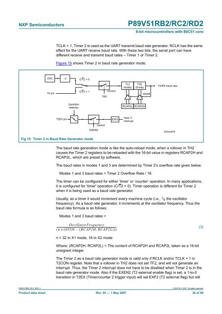
Figure 15 shows Timer 2 in baud rate generator mode:<br />
OSC ÷2<br />
C/T2 = 0<br />
T2 pin<br />
C/T2 = 1<br />
TR2<br />
control<br />
TL2<br />
(8-<strong>bit</strong>s)<br />
TH2<br />
(8-<strong>bit</strong>s)<br />
reload<br />
TX/RX baud rate<br />
transition<br />
detector<br />
RCAP2L RCAP2H<br />
T2EX pin<br />
control<br />
EXF2<br />
timer 2<br />
interrupt<br />
EXEN2<br />
002aaa526<br />
Fig 15. Timer 2 in Baud Rate Generator mode<br />
The baud rate generation mode is like the auto-reload mode, when a rollover in TH2<br />
causes the Timer 2 registers to be reloaded with the <strong>16</strong>-<strong>bit</strong> value in registers RCAP2H and<br />
RCAP2L, which are preset by software.<br />
The baud rates in modes 1 and 3 are determined by Timer 2’s overf<strong>low</strong> rate given be<strong>low</strong>:<br />
Modes 1 and 3 baud rates = Timer 2 Overf<strong>low</strong> Rate / <strong>16</strong><br />
The timer can be configured for either ‘timer’ or ‘counter’ operation. In many applications,<br />
it is configured for ‘timer' operation (C/T2 = 0). Timer operation is different for Timer 2<br />
when it is being used as a baud rate generator.<br />
Usually, as a timer it would increment every machine cycle (i.e., 1 ⁄ 6 the oscillator<br />
frequency). As a baud rate generator, it increments at the oscillator frequency. Thus the<br />
baud rate formula is as fol<strong>low</strong>s:<br />
Modes 1 and 3 baud rates =<br />
OscillatorFrequency<br />
------------------------------------------------------------------------------------------------<br />
( n × ( 65536 – ( RCAP2H,<br />
RCAP2L)<br />
))<br />
(3)<br />
n = <strong>32</strong> in X1 mode, <strong>16</strong> in X2 mode<br />
Where: (RCAP2H, RCAP2L) = The content of RCAP2H and RCAP2L taken as a <strong>16</strong>-<strong>bit</strong><br />
unsigned integer.<br />
The Timer 2 as a baud rate generator mode is valid only if RCLK and/or TCLK = 1 in<br />
T2CON register. Note that a rollover in TH2 does not set TF2, and will not generate an<br />
interrupt. Thus, the Timer 2 interrupt does not have to be disabled when Timer 2 is in the<br />
baud rate generator mode. Also if the EXEN2 (T2 external enable flag) is set, a 1-to-0<br />
transition in T2EX (Timer/counter 2 trigger input) will set EXF2 (T2 external flag) but will<br />
<strong>P89V51RB2</strong>_<strong>RC2</strong>_<strong>RD2</strong>_4<br />
© NXP B.V. 2007. All rights reserved.<br />
Product data sheet Rev. 04 — 1 May 2007 36 of 80