P89V51RB2/RC2/RD2 8-bit 80C51 5 V low power 16/32 ... - NetMedia
P89V51RB2/RC2/RD2 8-bit 80C51 5 V low power 16/32 ... - NetMedia
P89V51RB2/RC2/RD2 8-bit 80C51 5 V low power 16/32 ... - NetMedia

You also want an ePaper? Increase the reach of your titles
YUMPU automatically turns print PDFs into web optimized ePapers that Google loves.
NXP Semiconductors<br />
<strong>P89V51RB2</strong>/<strong>RC2</strong>/<strong>RD2</strong><br />
8-<strong>bit</strong> microcontrollers with <strong>80C51</strong> core<br />
(down-counting reload value)<br />
FFH<br />
FFH<br />
toggle<br />
EXF2<br />
OSC ÷6<br />
C/T2 = 0<br />
T2 pin<br />
C/T2 = 1<br />
TR2<br />
control<br />
TL2<br />
(8-<strong>bit</strong>s)<br />
TH2<br />
(8-<strong>bit</strong>s)<br />
RCAP2L RCAP2H<br />
underf<strong>low</strong> timer 2<br />
TF2<br />
interrupt<br />
overf<strong>low</strong><br />
count direction<br />
1 = up<br />
0 = down<br />
(up-counting reload value)<br />
T2EX pin<br />
002aaa525<br />
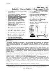
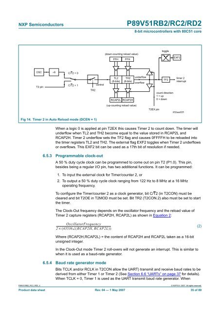
Fig 14. Timer 2 in Auto Reload mode (DCEN = 1)<br />
When a logic 0 is applied at pin T2EX this causes Timer 2 to count down. The timer will<br />
underf<strong>low</strong> when TL2 and TH2 become equal to the value stored in RCAP2L and<br />
RCAP2H. Timer 2 underf<strong>low</strong> sets the TF2 flag and causes 0FFFFH to be reloaded into<br />
the timer registers TL2 and TH2. The external flag EXF2 toggles when Timer 2 underf<strong>low</strong>s<br />
or overf<strong>low</strong>s. This EXF2 <strong>bit</strong> can be used as a 17th <strong>bit</strong> of resolution if needed.<br />
6.5.3 Programmable clock-out<br />
A 50 % duty cycle clock can be programmed to come out on pin T2 (P1.0). This pin,<br />
besides being a regular I/O pin, has two additional functions. It can be programmed:<br />
1. To input the external clock for Timer/counter 2, or<br />
2. To output a 50 % duty cycle clock ranging from 122 Hz to 8 MHz at a <strong>16</strong> MHz<br />
operating frequency.<br />
To configure the Timer/counter 2 as a clock generator, <strong>bit</strong> C/T2 (in T2CON) must be<br />
cleared and <strong>bit</strong> T2OE in T2MOD must be set. Bit TR2 (T2CON.2) also must be set to start<br />
the timer.<br />
The Clock-Out frequency depends on the oscillator frequency and the reload value of<br />
Timer 2 capture registers (RCAP2H, RCAP2L) as shown in Equation 2:<br />
OscillatorFrequency<br />
----------------------------------------------------------------------------------------<br />
2 × ( 65536∠( RCAP2H,<br />
RCAP2L)<br />
)<br />
(2)<br />
Where (RCAP2H,RCAP2L) = the content of RCAP2H and RCAP2L taken as a <strong>16</strong>-<strong>bit</strong><br />
unsigned integer.<br />
In the Clock-Out mode Timer 2 roll-overs will not generate an interrupt. This is similar to<br />
when it is used as a baud-rate generator.<br />
6.5.4 Baud rate generator mode<br />
Bits TCLK and/or RCLK in T2CON al<strong>low</strong> the UART) transmit and receive baud rates to be<br />
derived from either Timer 1 or Timer 2 (See Section 6.6 “UARTs” on page 37 for details).<br />
When TCLK = 0, Timer 1 is used as the UART transmit baud rate generator. When<br />
<strong>P89V51RB2</strong>_<strong>RC2</strong>_<strong>RD2</strong>_4<br />
© NXP B.V. 2007. All rights reserved.<br />
Product data sheet Rev. 04 — 1 May 2007 35 of 80