P89V51RB2/RC2/RD2 8-bit 80C51 5 V low power 16/32 ... - NetMedia
P89V51RB2/RC2/RD2 8-bit 80C51 5 V low power 16/32 ... - NetMedia
P89V51RB2/RC2/RD2 8-bit 80C51 5 V low power 16/32 ... - NetMedia

Create successful ePaper yourself
Turn your PDF publications into a flip-book with our unique Google optimized e-Paper software.
NXP Semiconductors<br />
<strong>P89V51RB2</strong>/<strong>RC2</strong>/<strong>RD2</strong><br />
8-<strong>bit</strong> microcontrollers with <strong>80C51</strong> core<br />
osc/6<br />
T0 pin<br />
C/T = 0<br />
C/T = 1<br />
control<br />
TL0<br />
(8-<strong>bit</strong>s)<br />
overf<strong>low</strong><br />
TF0<br />
interrupt<br />
TR0<br />
TnGate<br />
INT0 pin<br />
osc/2<br />
control<br />
TH0<br />
(8-<strong>bit</strong>s)<br />
overf<strong>low</strong><br />
TF1<br />
interrupt<br />
TR1<br />
002aaa522<br />
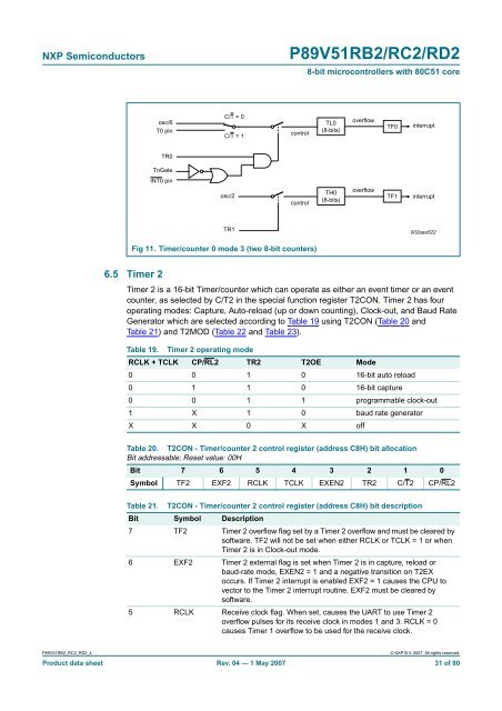
Fig 11. Timer/counter 0 mode 3 (two 8-<strong>bit</strong> counters)<br />
6.5 Timer 2<br />
Timer 2 is a <strong>16</strong>-<strong>bit</strong> Timer/counter which can operate as either an event timer or an event<br />
counter, as selected by C/T2 in the special function register T2CON. Timer 2 has four<br />
operating modes: Capture, Auto-reload (up or down counting), Clock-out, and Baud Rate<br />
Generator which are selected according to Table 19 using T2CON (Table 20 and<br />
Table 21) and T2MOD (Table 22 and Table 23).<br />
Table 19.<br />
Timer 2 operating mode<br />
RCLK + TCLK CP/RL2 TR2 T2OE Mode<br />
0 0 1 0 <strong>16</strong>-<strong>bit</strong> auto reload<br />
0 1 1 0 <strong>16</strong>-<strong>bit</strong> capture<br />
0 0 1 1 programmable clock-out<br />
1 X 1 0 baud rate generator<br />
X X 0 X off<br />
Table 20. T2CON - Timer/counter 2 control register (address C8H) <strong>bit</strong> allocation<br />
Bit addressable; Reset value: 00H<br />
Bit 7 6 5 4 3 2 1 0<br />
Symbol TF2 EXF2 RCLK TCLK EXEN2 TR2 C/T2 CP/RL2<br />
Table 21. T2CON - Timer/counter 2 control register (address C8H) <strong>bit</strong> description<br />
Bit Symbol Description<br />
7 TF2 Timer 2 overf<strong>low</strong> flag set by a Timer 2 overf<strong>low</strong> and must be cleared by<br />
software. TF2 will not be set when either RCLK or TCLK = 1 or when<br />
Timer 2 is in Clock-out mode.<br />
6 EXF2 Timer 2 external flag is set when Timer 2 is in capture, reload or<br />
baud-rate mode, EXEN2 = 1 and a negative transition on T2EX<br />
occurs. If Timer 2 interrupt is enabled EXF2 = 1 causes the CPU to<br />
vector to the Timer 2 interrupt routine. EXF2 must be cleared by<br />
software.<br />
5 RCLK Receive clock flag. When set, causes the UART to use Timer 2<br />
overf<strong>low</strong> pulses for its receive clock in modes 1 and 3. RCLK = 0<br />
causes Timer 1 overf<strong>low</strong> to be used for the receive clock.<br />
<strong>P89V51RB2</strong>_<strong>RC2</strong>_<strong>RD2</strong>_4<br />
© NXP B.V. 2007. All rights reserved.<br />
Product data sheet Rev. 04 — 1 May 2007 31 of 80