P89V51RB2/RC2/RD2 8-bit 80C51 5 V low power 16/32 ... - NetMedia
P89V51RB2/RC2/RD2 8-bit 80C51 5 V low power 16/32 ... - NetMedia
P89V51RB2/RC2/RD2 8-bit 80C51 5 V low power 16/32 ... - NetMedia

Create successful ePaper yourself
Turn your PDF publications into a flip-book with our unique Google optimized e-Paper software.
NXP Semiconductors<br />
<strong>P89V51RB2</strong>/<strong>RC2</strong>/<strong>RD2</strong><br />
8-<strong>bit</strong> microcontrollers with <strong>80C51</strong> core<br />
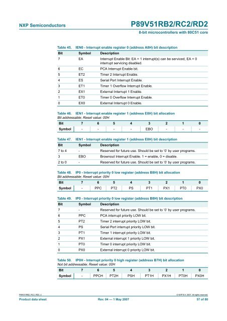
Table 45.<br />
IEN0 - Interrupt enable register 0 (address A8H) <strong>bit</strong> description<br />
Bit Symbol Description<br />
7 EA Interrupt Enable Bit: EA = 1 interrupt(s) can be serviced, EA = 0<br />
interrupt servicing disabled.<br />
6 EC PCA Interrupt Enable <strong>bit</strong>.<br />
5 ET2 Timer 2 Interrupt Enable.<br />
4 ES Serial Port Interrupt Enable.<br />
3 ET1 Timer 1 Overf<strong>low</strong> Interrupt Enable.<br />
2 EX1 External Interrupt 1 Enable.<br />
1 ET0 Timer 0 Overf<strong>low</strong> Interrupt Enable.<br />
0 EX0 External Interrupt 0 Enable.<br />
Table 46. IEN1 - Interrupt enable register 1 (address E8H) <strong>bit</strong> allocation<br />
Bit addressable; Reset value: 00H<br />
Bit 7 6 5 4 3 2 1 0<br />
Symbol - - - - EBO - - -<br />
Table 47. IEN1 - Interrupt enable register 1 (address E8H) <strong>bit</strong> description<br />
Bit Symbol Description<br />
7 to 4 - Reserved for future use. Should be set to ‘0’ by user programs.<br />
3 EBO Brownout Interrupt Enable. 1 = enable, 0 = disable.<br />
2 to 0 - Reserved for future use. Should be set to ‘0’ by user programs.<br />
Table 48. IP0 - Interrupt priority 0 <strong>low</strong> register (address B8H) <strong>bit</strong> allocation<br />
Bit addressable; Reset value: 00H<br />
Bit 7 6 5 4 3 2 1 0<br />
Symbol - PPC PT2 PS PT1 PX1 PT0 PX0<br />
Table 49. IP0 - Interrupt priority 0 <strong>low</strong> register (address B8H) <strong>bit</strong> description<br />
Bit Symbol Description<br />
7 - Reserved for future use. Should be set to ‘0’ by user programs.<br />
6 PPC PCA interrupt priority LOW <strong>bit</strong>.<br />
5 PT2 Timer 2 interrupt priority LOW <strong>bit</strong>.<br />
4 PS Serial Port interrupt priority LOW <strong>bit</strong>.<br />
3 PT1 Timer 1 interrupt priority LOW <strong>bit</strong>.<br />
2 PX1 External interrupt 1 priority LOW <strong>bit</strong>.<br />
1 PT0 Timer 0 interrupt priority LOW <strong>bit</strong>.<br />
0 PX0 External interrupt 0 priority LOW <strong>bit</strong>.<br />
Table 50. IP0H - Interrupt priority 0 high register (address B7H) <strong>bit</strong> allocation<br />
Not <strong>bit</strong> addressable; Reset value: 00H<br />
Bit 7 6 5 4 3 2 1 0<br />
Symbol - PPCH PT2H PSH PT1H PX1H PT0H PX0H<br />
<strong>P89V51RB2</strong>_<strong>RC2</strong>_<strong>RD2</strong>_4<br />
© NXP B.V. 2007. All rights reserved.<br />
Product data sheet Rev. 04 — 1 May 2007 57 of 80