P89V51RB2/RC2/RD2 8-bit 80C51 5 V low power 16/32 ... - NetMedia
P89V51RB2/RC2/RD2 8-bit 80C51 5 V low power 16/32 ... - NetMedia
P89V51RB2/RC2/RD2 8-bit 80C51 5 V low power 16/32 ... - NetMedia

You also want an ePaper? Increase the reach of your titles
YUMPU automatically turns print PDFs into web optimized ePapers that Google loves.
NXP Semiconductors<br />
<strong>P89V51RB2</strong>/<strong>RC2</strong>/<strong>RD2</strong><br />
8-<strong>bit</strong> microcontrollers with <strong>80C51</strong> core<br />
OSC ÷6<br />
C/T2 = 0<br />
T2 pin<br />
transition<br />
detector<br />
C/T2 = 1<br />
TR2<br />
control<br />
reload<br />
TL2<br />
(8-<strong>bit</strong>s)<br />
TH2<br />
(8-<strong>bit</strong>s)<br />
RCAP2L RCAP2H<br />
TF2<br />
timer 2<br />
interrupt<br />
T2EX pin<br />
EXF2<br />
EXEN2<br />
control<br />
002aaa524<br />
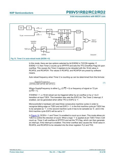
Fig 13. Timer 2 in auto-reload mode (DCEN = 0)<br />
In this mode, there are two options selected by <strong>bit</strong> EXEN2 in T2CON register. If<br />
EXEN2 = 0, then Timer 2 counts up to 0FFFFH and sets the TF2 (Overf<strong>low</strong> Flag) <strong>bit</strong> upon<br />
overf<strong>low</strong>. This causes the Timer 2 registers to be reloaded with the <strong>16</strong>-<strong>bit</strong> value in<br />
RCAP2L and RCAP2H. The values in RCAP2L and RCAP2H are preset by software<br />
means.<br />
Auto reload frequency when Timer 2 is counting up can be determined from this formula:<br />
SupplyFrequency<br />
-------------------------------------------------------------------------------<br />
( 65536∠( RCAP2H,<br />
RCAP2L)<br />
)<br />
(1)<br />
Where SupplyFrequency is either f osc (C/T2 = 0) or frequency of signal on T2 pin<br />
(C/T2 = 1).<br />
If EXEN2 = 1, a <strong>16</strong>-<strong>bit</strong> reload can be triggered either by an overf<strong>low</strong> or by a 1-to-0<br />
transition at input T2EX. This transition also sets the EXF2 <strong>bit</strong>. The Timer 2 interrupt, if<br />
enabled, can be generated when either TF2 or EXF2 is ‘1’.<br />
Microcontroller’s hardware will need three consecutive machine cycles in order to<br />
recognize falling edge on T2EX and set EXF2 = 1: in the first machine cycle pin T2EX has<br />
to be sampled as ‘1’; in the second machine cycle it has to be sampled as ‘0’, and in the<br />
third machine cycle EXF2 will be set to ‘1’.<br />
In Figure 14, DCEN = 1 and Timer 2 is enabled to count up or down. This mode al<strong>low</strong>s pin<br />
T2EX to control the direction of count. When a logic ‘1’ is applied at pin T2EX Timer 2 will<br />
count up. Timer 2 will overf<strong>low</strong> at 0FFFFH and set the TF2 flag, which can then generate<br />
an interrupt, if the interrupt is enabled. This timer overf<strong>low</strong> also causes the <strong>16</strong>-<strong>bit</strong> value in<br />
RCAP2L and RCAP2H to be reloaded into the timer registers TL2 and TH2.<br />
<strong>P89V51RB2</strong>_<strong>RC2</strong>_<strong>RD2</strong>_4<br />
© NXP B.V. 2007. All rights reserved.<br />
Product data sheet Rev. 04 — 1 May 2007 34 of 80