P89V51RB2/RC2/RD2 8-bit 80C51 5 V low power 16/32 ... - NetMedia
P89V51RB2/RC2/RD2 8-bit 80C51 5 V low power 16/32 ... - NetMedia
P89V51RB2/RC2/RD2 8-bit 80C51 5 V low power 16/32 ... - NetMedia

You also want an ePaper? Increase the reach of your titles
YUMPU automatically turns print PDFs into web optimized ePapers that Google loves.
NXP Semiconductors<br />
<strong>P89V51RB2</strong>/<strong>RC2</strong>/<strong>RD2</strong><br />
8-<strong>bit</strong> microcontrollers with <strong>80C51</strong> core<br />
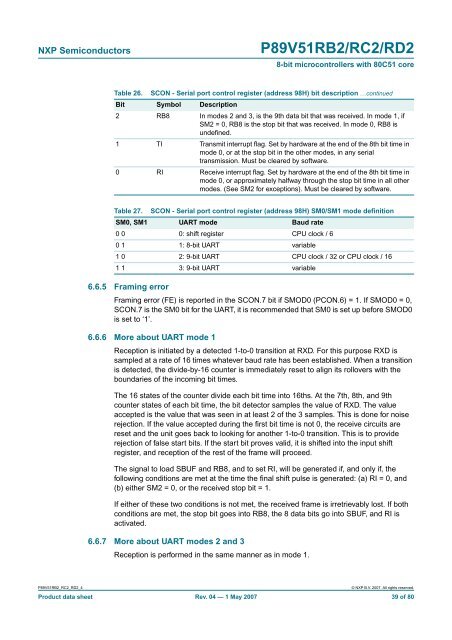
Table 26. SCON - Serial port control register (address 98H) <strong>bit</strong> description …continued<br />
Bit Symbol Description<br />
2 RB8 In modes 2 and 3, is the 9th data <strong>bit</strong> that was received. In mode 1, if<br />
SM2 = 0, RB8 is the stop <strong>bit</strong> that was received. In mode 0, RB8 is<br />
undefined.<br />
1 TI Transmit interrupt flag. Set by hardware at the end of the 8th <strong>bit</strong> time in<br />
mode 0, or at the stop <strong>bit</strong> in the other modes, in any serial<br />
transmission. Must be cleared by software.<br />
0 RI Receive interrupt flag. Set by hardware at the end of the 8th <strong>bit</strong> time in<br />
mode 0, or approximately halfway through the stop <strong>bit</strong> time in all other<br />
modes. (See SM2 for exceptions). Must be cleared by software.<br />
Table 27.<br />
6.6.5 Framing error<br />
SCON - Serial port control register (address 98H) SM0/SM1 mode definition<br />
SM0, SM1 UART mode Baud rate<br />
0 0 0: shift register CPU clock / 6<br />
0 1 1: 8-<strong>bit</strong> UART variable<br />
1 0 2: 9-<strong>bit</strong> UART CPU clock / <strong>32</strong> or CPU clock / <strong>16</strong><br />
1 1 3: 9-<strong>bit</strong> UART variable<br />
Framing error (FE) is reported in the SCON.7 <strong>bit</strong> if SMOD0 (PCON.6) = 1. If SMOD0 = 0,<br />
SCON.7 is the SM0 <strong>bit</strong> for the UART, it is recommended that SM0 is set up before SMOD0<br />
is set to ‘1’.<br />
6.6.6 More about UART mode 1<br />
Reception is initiated by a detected 1-to-0 transition at RXD. For this purpose RXD is<br />
sampled at a rate of <strong>16</strong> times whatever baud rate has been established. When a transition<br />
is detected, the divide-by-<strong>16</strong> counter is immediately reset to align its rollovers with the<br />
boundaries of the incoming <strong>bit</strong> times.<br />
The <strong>16</strong> states of the counter divide each <strong>bit</strong> time into <strong>16</strong>ths. At the 7th, 8th, and 9th<br />
counter states of each <strong>bit</strong> time, the <strong>bit</strong> detector samples the value of RXD. The value<br />
accepted is the value that was seen in at least 2 of the 3 samples. This is done for noise<br />
rejection. If the value accepted during the first <strong>bit</strong> time is not 0, the receive circuits are<br />
reset and the unit goes back to looking for another 1-to-0 transition. This is to provide<br />
rejection of false start <strong>bit</strong>s. If the start <strong>bit</strong> proves valid, it is shifted into the input shift<br />
register, and reception of the rest of the frame will proceed.<br />
The signal to load SBUF and RB8, and to set RI, will be generated if, and only if, the<br />
fol<strong>low</strong>ing conditions are met at the time the final shift pulse is generated: (a) RI = 0, and<br />
(b) either SM2 = 0, or the received stop <strong>bit</strong> = 1.<br />
If either of these two conditions is not met, the received frame is irretrievably lost. If both<br />
conditions are met, the stop <strong>bit</strong> goes into RB8, the 8 data <strong>bit</strong>s go into SBUF, and RI is<br />
activated.<br />
6.6.7 More about UART modes 2 and 3<br />
Reception is performed in the same manner as in mode 1.<br />
<strong>P89V51RB2</strong>_<strong>RC2</strong>_<strong>RD2</strong>_4<br />
© NXP B.V. 2007. All rights reserved.<br />
Product data sheet Rev. 04 — 1 May 2007 39 of 80