P89V51RB2/RC2/RD2 8-bit 80C51 5 V low power 16/32 ... - NetMedia
P89V51RB2/RC2/RD2 8-bit 80C51 5 V low power 16/32 ... - NetMedia
P89V51RB2/RC2/RD2 8-bit 80C51 5 V low power 16/32 ... - NetMedia

Create successful ePaper yourself
Turn your PDF publications into a flip-book with our unique Google optimized e-Paper software.
NXP Semiconductors<br />
<strong>P89V51RB2</strong>/<strong>RC2</strong>/<strong>RD2</strong><br />
8-<strong>bit</strong> microcontrollers with <strong>80C51</strong> core<br />
not cause a reload from (RCAP2H, RCAP2L) to (TH2,TL2). Therefore when Timer 2 is in<br />
use as a baud rate generator, T2EX can be used as an additional external interrupt, if<br />
needed.<br />
When Timer 2 is in the baud rate generator mode, one should not try to read or write TH2<br />
and TL2. Under these conditions, a read or write of TH2 or TL2 may not be accurate. The<br />
RCAP2 registers may be read, but should not be written to, because a write might overlap<br />
a reload and cause write and/or reload errors. The timer should be turned off (clear TR2)<br />
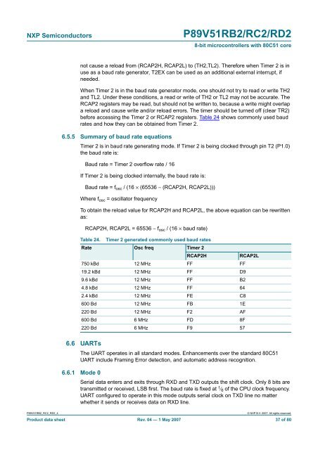
before accessing the Timer 2 or RCAP2 registers. Table 24 shows commonly used baud<br />
rates and how they can be obtained from Timer 2.<br />
6.5.5 Summary of baud rate equations<br />
Timer 2 is in baud rate generating mode. If Timer 2 is being clocked through pin T2 (P1.0)<br />
the baud rate is:<br />
Baud rate = Timer 2 overf<strong>low</strong> rate / <strong>16</strong><br />
If Timer 2 is being clocked internally, the baud rate is:<br />
Baud rate = f osc / (<strong>16</strong> × (65536 − (RCAP2H, RCAP2L)))<br />
Where f osc = oscillator frequency<br />
To obtain the reload value for RCAP2H and RCAP2L, the above equation can be rewritten<br />
as:<br />
RCAP2H, RCAP2L = 65536 − f osc / (<strong>16</strong> × baud rate)<br />
Table 24. Timer 2 generated commonly used baud rates<br />
Rate Osc freq Timer 2<br />
RCAP2H<br />
RCAP2L<br />
750 kBd 12 MHz FF FF<br />
19.2 kBd 12 MHz FF D9<br />
9.6 kBd 12 MHz FF B2<br />
4.8 kBd 12 MHz FF 64<br />
2.4 kBd 12 MHz FE C8<br />
600 Bd 12 MHz FB 1E<br />
220 Bd 12 MHz F2 AF<br />
600 Bd 6 MHz FD 8F<br />
220 Bd 6 MHz F9 57<br />
6.6 UARTs<br />
The UART operates in all standard modes. Enhancements over the standard <strong>80C51</strong><br />
UART include Framing Error detection, and automatic address recognition.<br />
6.6.1 Mode 0<br />
Serial data enters and exits through RXD and TXD outputs the shift clock. Only 8 <strong>bit</strong>s are<br />
transmitted or received, LSB first. The baud rate is fixed at 1 ⁄ 6 of the CPU clock frequency.<br />
UART configured to operate in this mode outputs serial clock on TXD line no matter<br />
whether it sends or receives data on RXD line.<br />
<strong>P89V51RB2</strong>_<strong>RC2</strong>_<strong>RD2</strong>_4<br />
© NXP B.V. 2007. All rights reserved.<br />
Product data sheet Rev. 04 — 1 May 2007 37 of 80