Amp 200-300.pdf - AudioSource
Amp 200-300.pdf - AudioSource
Amp 200-300.pdf - AudioSource

Create successful ePaper yourself
Turn your PDF publications into a flip-book with our unique Google optimized e-Paper software.
AMP<strong>200</strong> / AMP300<br />
OWNER’S MANUAL<br />
AMP<strong>200</strong> / AMP300<br />
Home Audio Multi-Zone Power <strong>Amp</strong>lifier<br />
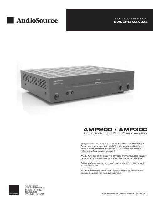
Congratulations on your purchase of the <strong>AudioSource</strong>® AMP<strong>200</strong>/300.<br />
Please take a few moments to read this entire manual, and be sure to<br />
retain this document for future reference. Please read and observe all<br />
safety instructions detailed on page 2.<br />
NOTE: if any part of this product is damaged or missing, please call your<br />
dealer or <strong>AudioSource</strong>® directly at 1.800.435.7115 or 503.286.9300.<br />
Please read your warranty and retain your receipt and original carton for<br />
possible future use.<br />
For more information about <strong>AudioSource</strong>® electronics, speakers and<br />
accessories please visit www.audiosource.net<br />
<strong>AudioSource</strong>®<br />
9300 North Decatur St.<br />
Portland, OR 97203<br />
503.286.9300<br />
www.audiosource.net AMP<strong>200</strong> / AMP300 Owner’s Manual 8.06 8100.0303B
AMP<strong>200</strong> / AMP300<br />
OWNER’S MANUAL<br />
CAUTION<br />
RISK OF ELECTRICAL SHOCK<br />
DO NOT OPEN<br />
CAUTION: TO REDUCE THE RISK OF ELECTRIC SHOCK, DO NOT REMOVE THE COVER. NO<br />
USER SERVICABLE PARTS INSIDE. REFER SERVICING TO QUALIFIED PERSONNEL!<br />
EXPLANATION OF<br />
SAFETY SYMBOLS<br />
The exclamation point within an equilateral triangle is intended to alert the user of the presence of important<br />
operating and maintenance (servicing) instructions in the literature accompanying the appliance.<br />
The lightning flash with the arrowhead symbol within an equilateral triangle is intended to alert the user to the<br />
presence of uninsulated “dangerous voltage” within the products’ enclosure that may be of sufficient magnitude<br />
to constitute a risk of electric shock to persons.<br />
IMPORTANT SAFETY INSTRUCTIONS<br />
1. Read these instructions.<br />
2. Keep these instructions.<br />
3. Heed all warnings.<br />
4. Follow all instructions.<br />
5. Do not use this apparatus near water.<br />
6. Clean only with dry cloth.<br />
7. Do not block any ventilation openings. Install in accordance with the<br />
manufacturer’s instructions.<br />
8. Do not install near heat sources such as radiators, heat registers, stoves,<br />
or other apparatus (including amplifiers) that produce heat.<br />
9. Do not defeat the safety purpose of the polarized or grounding type<br />
plug. A polarized plug has two blades with one wider than the other. A<br />
grounding type plug has two blades and a third grounding prong. The<br />
wide blade or third prong are provided for your safety. If the provided plug<br />
does not fit into your outlet, consult an electrician for replacement of the<br />
obsolete outlet.<br />
10. Protect the power cord from being walked on or pinched particularly at<br />
the plugs, convenience receptacles, and at the point where they exit from<br />
the appliance.<br />
11. Only use attachments or accessories specified by the manufacturer.<br />
12. Unplug the apparatus during lightning storms or when unused for long<br />
periods of time.<br />
13. Refer all servicing to qualified personnel. Servicing is required when the<br />
apparatus has been damaged in any way, such as power supply cord or<br />
plug is damaged, liquid has been spilled or objects have fallen into the<br />
apparatus, the apparatus has been exposed to rain or moisture, does not<br />
operate normally, or has been dropped.<br />
• TO PREVENT FIRE OF SHOCK HAZARD, DO NOT USE THIS PLUG WITH AN EXTENSION CORD, RECEPTICLE OR OTHER OUTLET UNLESS THE<br />
BLADES CAN BE FULLY INSERTED TO PREVENT BLADE EXPOSURE.<br />
• TO PREVENT FIRE OR SHOCK HAZARD, DO NOT EXPOSE THIS APPLIANCE TO RAIN OR MOISTURE<br />
• TO PREVENT ELECTRICAL SHOCK, MATCH WIDE BLADE PLUG TO WIDE SLOT, FULLY INSERT.<br />
MAGNETIC FIELD: !!CAUTION!! Do not locate sensitive high-gain equipment such as preamplifiers or tape decks directly above or below the unit. Because<br />
this amplifier has a high power density, it has a strong magnetic field, which can induce hum into unshielded devices that are located nearby. The field is<br />
strongest just above and below the unit. If an equipment rack is used, we recommend locating the amplifier(s) in the bottom of the rack and the preamplifier<br />
or other sensitive equipment at the top.<br />
2 9300 North Decatur St. Portland, OR 97203 • 503.286.9300 • www.audiosource.net
AMP<strong>200</strong> / AMP300<br />
OWNER’S MANUAL<br />
Technical Support<br />
If any part of this product is damaged or missing, please call your dealer or<br />
<strong>AudioSource</strong>® directly at toll free 1.800.435.7115 or locally 503.286.9300.<br />
Limited Warranty<br />
<strong>AudioSource</strong>® warrants its amplifier products against defects in materials<br />
and workmanship for a limited period of time. For a period of two years from<br />
date of original purchase, we will repair or replace the product, at our option,<br />
without charge for parts and labor. Customer must pay all parts and labor<br />
charges after the limited warranty period expires. The limited warranty period<br />
for factory refurbished products expires after ninety (90) days from date of<br />
original purchase.<br />
This limited warranty applies only to purchases from authorized <strong>AudioSource</strong>®<br />
Electronics retailers. This limited warranty is extended only to the original<br />
purchaser and is valid only to consumers in the United States.<br />
Consumers are required to provide a copy of the original sales invoice from<br />
an authorized <strong>AudioSource</strong>® dealer when making a claim against this limited<br />
warranty. This limited warranty only covers failures due to defects in materials<br />
or workmanship that occur during normal use. It does not cover failures<br />
resulting from accident, misuse, abuse, neglect, mishandling, misapplication,<br />
alteration, faulty installation, modification, service by anyone other than<br />
<strong>AudioSource</strong>®, or damage that is attributable to Acts of God. It does not<br />
cover costs of transportation to <strong>AudioSource</strong>® or damage in transit. The<br />
customer should return his defective product, freight prepaid and insured, to<br />
<strong>AudioSource</strong>® only after receiving a Return Authorization.<br />
This warranty will become void if the serial number identification has been<br />
wholly or partially removed, altered or erased. Repair or replacement under<br />
the terms of this warranty does not extend the terms of this warranty. Should<br />
a product prove to be defective in workmanship or material, the consumer’s<br />
sole remedies will be repair or replacement as provided under the terms<br />
of this warranty. Under no circumstances shall <strong>AudioSource</strong>® be liable for<br />
loss or damage, direct, consequential or incidental, arising out of the use of<br />
or inability to use the product. There are no express warranties other than<br />
described above.<br />
9300 North Decatur St. Portland, OR 97203 • 503.286.9300 • www.audiosource.net 3
AMP<strong>200</strong> / AMP300<br />
OWNER’S MANUAL<br />
Model AMP<strong>200</strong><br />
Stereo Power <strong>Amp</strong>lifier<br />
ON / STANDBY<br />
Power<br />
Speakers<br />
Balance Trim<br />
Volume Trim<br />
ON<br />
A<br />
OFF<br />
B<br />
1<br />
2<br />
Left<br />
3<br />
Right<br />
4<br />
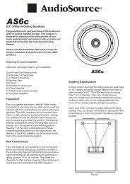
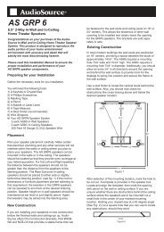
Figure 1. Front Panel<br />
FRONT PANEL CONTROLS<br />
1. Power<br />
The front panel power switch switches the AMP<strong>200</strong>/300 on or off. Blue<br />
and red LEDs behind the faceplate lens indicate power status. Whenever<br />
the amplifier’s power switch is in the “ON” position and the amplifier is in<br />
“Active” status the lens is illuminated blue. If the amplifier is “ON” but in<br />
“Standby” status the lens is illuminated red.<br />
2. Speaker Selector<br />
Selects speaker set ( A or B )<br />
3. Balance Trim<br />
Fades speaker output between the Right and Left Channels<br />
4. Volume Trim<br />
Allows fine adjustment of amplifier volume.<br />
6<br />
<br />
5<br />
7 8 9 10 11 12 13 14 15 16<br />
17<br />
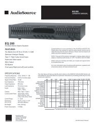
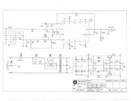
REAR PANEL CONTROLS<br />
5. Line 1 Input<br />
A priority switching input that can be used for a second source and will<br />
take over when a signal is present and has at least a 5mV level. Whenever<br />
there is no signal at this input, or a signal with less than 5mV level, the<br />
amplifier switches back to the Line 2 or “primary” input.<br />
6. Speaker Level Input Line Select<br />
Switches the input of the speaker level input to Line 1 or Line 2.<br />
7. Speaker Level Input<br />
Can be used to connect a source with speaker level output instead of line<br />
level outputs. Use the Speaker Level Input Line Select to route the source<br />
to Line 1 or Line 2.<br />
8. Line 2 Input/Output<br />
The primary line level input and output.<br />
9. Delay Time<br />
Allows for a 3-15 second delay to be set and accomodate the source<br />
connected to the Line 1 input.<br />
10. Master Level Controls<br />
Provides indepedent adjustment of Left and Right channel maximum<br />
level.<br />
11. Mode Select Switch<br />
Switches the amplifier from Stereo mode to Bridged mode<br />
Figure 2. Rear Panel<br />
12. 12V Trigger<br />
Allows the AMP<strong>200</strong>/300 to be powered on by other electronics or to power<br />
on other electronics via a 3.5mm mini phone plug cable.<br />
13. Power Mode<br />
Sets the power on option of the AMP<strong>200</strong>/300. Set it to Normal for manual<br />
power on/off. Set to Auto-On for signal sensing. Set to Trigger if the 12V<br />
Trigger input is used.<br />
14. Right Channel Speaker Output<br />
Right output stage for both Speaker outputs ( A and B )<br />
15. Left Channel Speaker Output<br />
Left output stage for both Speaker outputs ( A and B )<br />
16. Mains Power Inlet & Fuseholder<br />
Accepts IEC type linecord. Fuse in integrated holder provides safety<br />
protection from fault conditions: only replace fuse with one of same type<br />
and rating.<br />
17. Mains Voltage Selector<br />
Voltage selection switch is preset for use in market of sale. Installed mains<br />
fuse must be of type and rating marked on amplifier for use at local mains<br />
voltage.<br />
4 9300 North Decatur St. Portland, OR 97203 • 503.286.9300 • www.audiosource.net
AMP<strong>200</strong> / AMP300<br />
OWNER’S MANUAL<br />
FRONT PANEL CONTROLS<br />
The front panel power switch switches the AMP<strong>200</strong>/300 on or off. Blue<br />
and red LEDs behind the faceplate lens indicate power status. Whenever<br />
the amplifier’s power switch is in the “ON” position and the amplifier is in<br />
“Active” status the lens is illuminated blue. If the amplifier is “ON” but in<br />
“Standby” status the lens is illuminated red.<br />
REAR PANEL CONTROLS<br />
The AMP<strong>200</strong>/300 can be turned on and off independently via the power<br />
switch on the front panel, by signal sensing, or remotely by a triggered<br />
DC input. Switch 13 , located on the lower edge of the rear panel of the<br />
amplifier, selects turn-on functions of the AMP<strong>200</strong>/300. If you would like to<br />
control the unit’s power on / power off status manually from the front, place<br />
the switch in the “Normal” position. If you would like to control the unit’s<br />
power-on / power-off status by means of signal sensing, place the switch<br />
in the “AUTO ON” position. If you would like to control the unit’s power-on /<br />
power-off status by a DC remote trigger, place the switch in the “TRIGGER”<br />
position, and connect the remote triggering cable from your triggering<br />
device to the jack labeled “IN” next to the switch.<br />
Begin Master Level control setup by adjusting the front panel “Volume Trim”<br />
to its fully clockwise position. Set the front panel “Balance Trim” to its center<br />
detent position. Now adjust both the Left and Right Channel Master Level<br />
controls to set a “Maximum” desired volume for the AMP<strong>200</strong>/300 in its<br />
application, as well as setting an appropriate “Balance” from left to right.<br />
Now use the front panel Volume and Balance Trim controls to make fine<br />
adjustments to your setup in this application.<br />
5<br />
<br />
<br />
&<br />
8<br />
RCA INPUT/OUTPUT<br />
<br />
<br />
<br />
<br />
<br />
<br />
<br />
<br />
<br />
<br />
<br />
<br />
<br />
<br />
<br />
<br />
<br />
Figure 6. RCA Inputs<br />
There are 2 pairs of RCA inputs on the back panel of the AMP<strong>200</strong>/300.<br />
These RCA inputs are labelled as “Line 1 Input” and “Line 2 Input”. They<br />
are also designated with an “R” or an “L” as Right channel or Left Channel<br />
inputs respectively.<br />
Figure 3. 12V Trigger<br />
Figure 4. Power Mode<br />
Use a 3.5mm phone plug (in the “IN” connector) to make this connection:<br />
the tip of the connector is (+) positive, and the sleeve of the connector is<br />
(-) negative. A second jack in the same block is labeled “OUT”. This allows<br />
for remote turn-on of other devices when the AMP<strong>200</strong>/300 is powered on.<br />
Use the same polarity for the terminals of this plug. Please read the owner’s<br />
manual for any devices you are attempting to connect in this manner to<br />
ensure compatibility.<br />
Note: The front panel power switch must be in the “ON” position for the 12V<br />
triggers or “Auto ON” features to operate.<br />
10<br />
MASTER LEVEL CONTROLS<br />
These level controls allow independent volume adjustment for each channel.<br />
At the bottom left of the rear panel, there are 2 screwdriver adjustment<br />
knobs which set the maximum level of the channel identified by the channel<br />
designator below it.<br />
“Line 2 Input” should be used as the “primary” or normal input for various<br />
line level sources that may be available to the amplifier. “Line 1 Input” is<br />
a priority switching input that can be used for a second input, such as the<br />
output of a local source, and will take over as the selected input whenever<br />
a signal with a minimum of 5mV of level is present. Whenever there is no<br />
signal at the “Line 1 Input” RCAs, or a signal with less than 5mV level, the<br />
input will revert back to the normal Line 2 input signal.<br />
An adjustable delay, of from 3 seconds to 15 seconds, can be set to<br />
accommodate the nature of the source connected to the “Line 1 Input”<br />
RCAs. As an example, if the “Line 1 Input” source was a CD Changer, the<br />
delay could be adjusted to prevent switching back to the “Line 2 Input”<br />
source while the changer moves from one disc to another.<br />
7<br />
SPEAKER LEVEL INPUT<br />
The AMP<strong>200</strong>/300 provides a pair of speaker level inputs for those<br />
applications where either of the sources has only speaker level output signal<br />
available. The switch routes the speaker level signal to either the Line 1 or<br />
Line 2 input.<br />
Figure 5. Master Level<br />
The volume range is labeled Minimum to Maximum. Rotate the knob<br />
clockwise to increase output, and counter-clockwise to decrease output.<br />
These adjustments set the master level and if not configured at initial setup<br />
of the AMP<strong>200</strong>/300 may adversely affect the performance of the amplifier.<br />
9300 North Decatur St. Portland, OR 97203 • 503.286.9300 • www.audiosource.net 5
AMP<strong>200</strong> / AMP300<br />
OWNER’S MANUAL<br />
11 MODE SWITCH<br />
14 & 15<br />
SPEAKER TERMINALS<br />
Terminals are provided for “A” and “B” pairs of speakers for each channel. If<br />
you will be using the amplifier as a stereo amplifier (i.e. not a bridged amplifier),<br />
connect the speaker’s positive (red) terminal to the amplifier’s positive (red)<br />
terminal, and the speaker’s negative (black) terminal to the amplifier’s negative<br />
(black) terminal (immediately beside the positive terminal).<br />
Figure 7. Mode Select Switch<br />
To the right of the Master Level controls is a switch labeled “Mode” with<br />
“Stereo” and “Bridged” as options. If you will be connecting one or two pair<br />
of speakers to the amplifier, place the switch in the “Stereo” position.<br />
NOTE: If you are using the AMP<strong>200</strong>/300 in stereo mode, with 2 sets of<br />
speakers (A and B), make sure each speaker has an impedance of 8 ohms<br />
or greater.<br />
When used in “Bridged” mode, the amplifier is a single channel Mono<br />
amplifier.<br />
NOTE: Use the appropriate gauge speaker wire when connecting speakers<br />
to the AMP<strong>200</strong>/300.<br />
If using one pair of channels bridged, place the “Mode” switch in the “Bridged”<br />
position and use both RED terminals to connect to the speaker.<br />
NOTE: When in “Bridged” mode make sure to connect the speaker’s negative<br />
(black) terminal to the amplifier’s positive (red) terminal of the right channel and<br />
the speaker’s positive (red) terminal to the amplifier’s positive (red) terminal of<br />
the left channel<br />
If you will be using a pair of channels to power a single mono speaker, place<br />
the switch in the “Bridged” position, and be sure to read the section titled<br />
“Speaker Terminals” below.<br />
For the amplifier to operate properly in bridged mode you should have both<br />
“Right and Left” inputs connected to the amplifier. The amplifier will sum<br />
these signals and create your Mono source.<br />
NOTE: Both of the “Master Level” adjustments should should be set to the<br />
center, 12 o’clock position for normal amplifier operation in “Bridged” mode.<br />
NOTE: The AMP<strong>200</strong> supplies 250W in bridged mode, while the AMP300<br />
supplies 470W in bridged mode. Please verify that your speakers are capable<br />
of handling such power to avoid possible damage!<br />
Figure 8. Speaker Terminals<br />
NOTE: Only one pair of channels can be bridged together. Do not attempt to<br />
bridge both A & B speaker terminals, as this may result in a lower impedance<br />
than the amplifier is designed to accommodate and may damage your<br />
amplifier. The minimum impedance for the total load connected to a pair of<br />
channels in the bridged mode is 8 ohms.<br />
16 & 17<br />
MAINS POWER INLET/FUSE/<br />
VOLTAGE SELECTOR<br />
Power inlet accepts the IEC type linecord supplied with the amplifier. Fuse<br />
in integrated holder provides safety protection from fault conditions: only<br />
replace fuse with one of same type and rating.<br />
This amplifier is configured for operation at the mains voltage of the market<br />
in which it is sold.<br />
The AMP<strong>200</strong>/300 can be configured for operation from either 115V ~60Hz<br />
or 230V ~50Hz AC mains. Installed mains fuse must be of type and rating<br />
marked on amplifier corresponding to configured AC mains voltage.<br />
Should you wish to configure the AMP<strong>200</strong>/300 for use at the alternate AC<br />
mains voltage, please contact <strong>AudioSource</strong> support at 1.800.435.7115.<br />
6 9300 North Decatur St. Portland, OR 97203 • 503.286.9300 • www.audiosource.net
AMP<strong>200</strong> / AMP300<br />
OWNER’S MANUAL<br />
<br />
APPLICATIONS<br />
<br />
<br />
NOTE: It should be noted that the AMP<strong>200</strong>/300 is rated to operate into a<br />
minimum 8-ohm bridged load. Therefore, if you are using more than a single<br />
8-ohm loudspeaker in bridged mode you should consider using an impedance<br />
matching speaker selector, such as the Phoenix Gold® Innovative Home ISM4,<br />
ISM6 or ISM8 or possibly using an impedance matching volume control, such as<br />
the Phoenix Gold® Innovative Home VMT1 in a weatherproof housing available at<br />
your favorite DIY store or electrical supply. The choice of a volume control would<br />
allow you the additional flexibility of being able to attenuate the volume whenever<br />
necessary.<br />
<br />
<br />
<br />
<br />
<br />
<br />
<br />
<br />
<br />
<br />
<br />
<br />
<br />
<br />
<br />
<br />
<br />
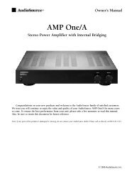
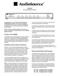
STEREO SETUP<br />
In this configuration, the mode switch is set to “Stereo”. Connect the line out<br />
jacks from a stereo preamplifier or source to the Line 2 input jacks of your<br />
AMP<strong>200</strong>/300 (Figure 9). Next connect your speakers to the terminals marked<br />
“SPEAKER A” observing proper polarity (see “Speaker Terminals” Page 6).<br />
Connect a second (optional) pair of speakers to the terminals marked “SPEAKER<br />
B”. Select the “A” speakers using the front panel speaker selection buttons.<br />
<br />
<br />
<br />
<br />
<br />
<br />
<br />
<br />
<br />
<br />
<br />
<br />
<br />
<br />
<br />
<br />
<br />
<br />
<br />
<br />
<br />
<br />
The audio output of a local source, such as an MP3 Player, CD, television,<br />
computer, etc., is connected to the AMP<strong>200</strong>/300 via the Line 1 inputs, and<br />
whenever the local source is active its signal will take priority over the distributed<br />
audio signal present at Line 2 . However, the distributed audio signal will still<br />
be present at the Line 2 input. In this circumstance the audio output of the<br />
local source will be heard via the AMP<strong>200</strong>/300. Once the local source is turned<br />
off or muted, the AMP<strong>200</strong>/300 will automatically switch back the distributed<br />
audio system as an audio source, assuming the local source remains inactive.<br />
The delay time adjustment determines when switch back to the normal source<br />
will occur. This set up assumes all incoming signals are at line level and not at<br />
speaker level.<br />
<br />
Figure 10. Line Level with Multiple Sources<br />
<br />
<br />
<br />
<br />
<br />
<br />
MONO SETUP<br />
Figure 9. Stereo Setup<br />
In this configuration, the mode switch is set to “Bridged”. Connect the line<br />
out from a preamplifier to the right and left Line 2 inputs of your AMP<strong>200</strong>/300.<br />
Connect your mono speaker to the terminals of your AMP<strong>200</strong>/300 (see “Speaker<br />
Terminals” on Page 6). Use the “Master Level” controls on the rear panel to<br />
adjust the volume. Leave the balance set to the center detent position.<br />
<br />
<br />
<br />
<br />
<br />
<br />
<br />
<br />
<br />
<br />
<br />
<br />
<br />
<br />
<br />
<br />
<br />
SETUP FOR MULTIPLE SOURCE<br />
In the application shown in Figure 10, a distributed audio system is connected<br />
to the AMP<strong>200</strong>/300 as a local zone amplifier via the Line 2 inputs. Normally<br />
the distributed audio system will be the audio source for the AMP<strong>200</strong>/300. The<br />
distributed audio is then passed on to be used by additional zones or sub zones<br />
in the distributed system via the Line 2 outputs.<br />
<br />
<br />
Figure 11. Speaker Level with Multiple Sources<br />
If the whole house distributed audio was only available as a speaker level signal<br />
you could connect it to the “Speaker In” connections and set the routing switch<br />
to the “Line 2” position, the right hand position of the switch (Figure 11).The AMP<br />
<strong>200</strong>/300 will no longer be able to pass the Whole House Distributed Audio to<br />
another zone via the Line 2 Output. If you have any questions regarding how to<br />
set this up, please call <strong>AudioSource</strong>® Tech support at 1.800.435.7115<br />
9300 North Decatur St. Portland, OR 97203 • 503.286.9300 • www.audiosource.net 7
ON<br />
OFF<br />
ON<br />
OFF<br />
AMP <strong>200</strong> / AMP300<br />
OWNER’S MANUAL<br />
16.5”<br />
(419mm)<br />
AMP <strong>200</strong> SPECIFICATIONS<br />
Stereo (8 ohm): 80W RMS per channel at 8 ohms,<br />
20Hz - 20kHz,