ATC6DM Manual.pdf - AudioSource
ATC6DM Manual.pdf - AudioSource
ATC6DM Manual.pdf - AudioSource

Create successful ePaper yourself
Turn your PDF publications into a flip-book with our unique Google optimized e-Paper software.
INNOVATIVE HOME<br />
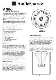
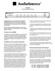
<strong>ATC6DM</strong><br />
6.5” 2-Way In-Ceiling Speakers<br />
Congratulations on your purchase of the Phoenix Gold<br />
Innovative Home ATC Dual Mono (DM) In-Ceiling<br />
Speaker System. This product is designed to reproduce<br />
the audio portion of your home entertainment environment<br />
with accuracy and detail that will satisfy the most<br />
discriminating listener.<br />
Please read this Installation <strong>Manual</strong> to ensure the<br />
proper installation and performance of your ATC<br />
Series speakers.<br />
Preparing for your Installation<br />
Gather the necessary tools for your installation.<br />
You will need the following tools:<br />
1) A Keyhole or Drywall Saw<br />
2) A Phillips Screwdriver<br />
3) Masking Tape<br />
4) A Pencil<br />
5) A Tape Measure<br />
6) A Stud Finder (recommended)<br />
7) Your ATC-DM speaker<br />
Placement<br />
Plan your speaker placement carefully. Make certain<br />
that electrical, plumbing and any other services will not<br />
interfere within the ceiling where you plan to install your<br />
speakers. The ATC-DM speaker can be mounted in<br />
walls, but are typically used in ceilings. The speaker<br />
should be located so that it provides even coverage<br />
at your listening position.<br />
ATC-DM Summed Mono Speaker Operation<br />
The ATC-DM speaker is designed for use in areas where<br />
even distribution of sound is desired but stereo imaging<br />
is not practical because of space limitations, such as a<br />
bathroom or long hallway.<br />
With a dual voice coil woofer and dual tweeters, the<br />
ATC-DM speaker can sum stereo amplifier channels<br />
into a mono audio signal. Two pairs of input terminals<br />
allow connection of both channels from a stereo amplifier<br />
to a single ATC-DM speaker. Set the switch on the back<br />
of the ATC-DM speaker to 16Ω for summed mono<br />
operation.<br />
Caution! Amplifier damage will occur if the ATC-DM is<br />
set to 8Ω with two amplifier channels connected!<br />
ATC-DM Conventional Speaker Operation<br />
An ATC-DM speaker can be used to reproduce a single<br />
channel of audio by making connection to either set of<br />
input terminals and setting the switch on the back of the<br />
speaker to 8Ω. In this configuration, both woofer voice<br />
coils and both tweeters are driven in parallel by the<br />
connected amplifier channel.<br />
New Construction<br />
If you are installing your speakers in new construction<br />
before the finished walls go up, Phoenix Gold Innovative<br />
Home offers New Construction Brackets, which provide<br />
a stable frame that can be fastened to the wall studs or<br />
ceiling joists on 16” or 24” centers. This allows the<br />
sheet rock or other surface covering to be installed<br />
and provides a template to cut the opening for the<br />
ATC-DM speaker.<br />
Existing Construction<br />
In most modern buildings ceiling joists are positioned<br />
on 16” centers, providing a space between the joists of<br />
approximately 14 3/8”. The specifications chart shows<br />
the appropriate cut out sizes (p. 4). Additionally, you<br />
should allow an extra 3/4” in all directions behind the<br />
ceiling surface to allow room for the screw clamps that<br />
mount the speaker to the ceiling to swing into position.<br />
Use a stud finder to locate the joists behind the ceiling<br />
surface. Also, you should now check for obstructions<br />
like cross bracing in front of and behind the desired<br />
speaker location.
After selecting the mounting location, mark the hole to<br />
be cut out. A template is provided in the speaker box.<br />
Locate and align the template, then mark with pencil<br />
on the ceiling surface. If you are unsure whether there<br />
are obstructions behind the ceiling surface where the<br />
speakers are to be mounted, cut a small hole in the<br />
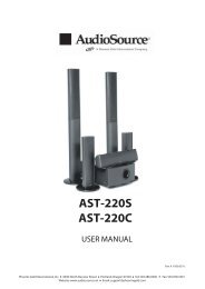
center of your marked mounting location. Holding your<br />
drywall saw at a 45 degree angle (See Figure 1), cut a<br />
square hole that you can use to locate any obstructions,<br />
should they exist.<br />
ROOM<br />
Figure 1<br />
The 45 degree wedge shape of the removed surfacing<br />
material will make replacement, if necessary, a much<br />
easier task and yield a better finish when patching the<br />
work.<br />
Once it has been determined that there are no obstructions,<br />
cut the hole to mount the speaker using the drywall<br />
saw at a 90 degree angle to the ceiling surface. Cover<br />
the raw edges of the wallboard with masking tape<br />
(See Figure 2). This will prevent the back pressure of the<br />
speaker from blowing loose gypsum dust out and onto<br />
the painted ceiling surface after installation. Do not allow<br />
the tape to extend more than 1/4” beyond the edge of the<br />
hole into the room. The frame of the speaker will cover<br />
and hide the tape.<br />
Masking T.ape<br />
ROOM<br />
Figure 2<br />
Next run your speaker wire to your speaker locations.<br />
A UL rated CL3 speaker wire is recommended when<br />
running wire inside your walls. In many areas it may<br />
be required by code. When running your speaker wire<br />
you should avoid having the speaker wire run parallel<br />
to the 120V power lines to avert picking up hum and<br />
interference from the power service. If the speaker<br />
wire needs to cross a 120V power line at a right angle<br />
this is acceptable and will not create a problem.<br />
If you are uncomfortable with running the speaker wire<br />
yourself in existing construction, it is recommended that<br />
you retain a qualified custom home installation specialist<br />
or electrician.<br />
Installing the Speaker<br />
Installation Tip! To further enhance the performance<br />
of your ATC-DM speaker, the ceiling joist cavity where<br />
you plan to place your speaker can be stuffed with a<br />
generous quantity of fiberglass insulation. Stuff the area<br />
in front of and behind the speaker opening with 6” thick<br />
insulation to a depth of approximately 2 feet beginning<br />
1 foot in front and 1 foot behind the speaker opening. If<br />
the insulation is foil or paper backed, face the backing<br />
away from the ATC-DM speaker. The addition of this<br />
insulation will help prevent unwanted transfer of sound<br />
into the otherwise large and resonant cavity of the uninsulated<br />
ceiling.<br />
2<br />
Grill Removal for Installation<br />
CAUTION! The grill is held in place by contact pressure<br />
around the edges where it attaches to the speaker frame.<br />
To avoid difficulty reinstalling the grill, care should be taken<br />
to not distort its shape<br />
while removing it.<br />
1/4"(6mm)<br />
While looking at the rear<br />
of the speaker assembly,<br />
rotate two of the adjacent<br />
mounting clamps outward<br />
and then evenly press them<br />
towards the grill. The clamp<br />
screws contact the inner<br />
surface of the grill, pushing<br />
it gently out of its mounting<br />
groove (Figure 3). Only lift<br />
the grill 1/4" (6mm) at this<br />
location. Next use the other<br />
mounting clamps to further<br />
loosen the grill. Use care to<br />
not distort the grill shape.<br />
Connecting the Speaker<br />
Figure 3<br />
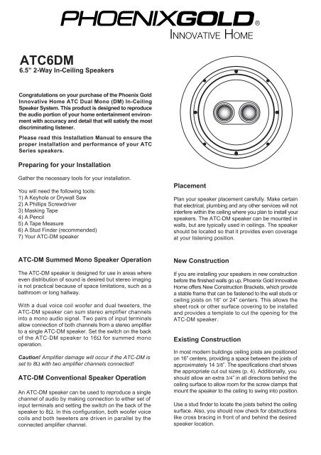
It is now time to connect the speaker wire to the speaker.<br />
Your speaker wire is usually coded to identify each<br />
conductor as either positive or negative. This can be<br />
by color coding, or one conductor may have a printed<br />
marking or at least a rib along one edge that you will not<br />
find on the other. Identify which type of polarity coding<br />
that your wire is using. You must carefully observe that<br />
the positive terminal of the speaker output on your<br />
amplifier is connected to the positive terminal of the<br />
ATC-DM speaker. Likewise, the negative terminal of the<br />
amplifier’s speaker output should be connected to the<br />
negative terminal of the ATC-DM speaker (Figure 4).<br />
(+) Amp<br />
(-) Amp<br />
(-) Amp<br />
(+) Amp<br />
(R)<br />
(L)<br />
(+) Amp (R or L)<br />
(-) Amp<br />
Figure 4<br />
Right and Left<br />
Channels are<br />
Both Connected<br />
(Summed<br />
Mono Speaker)<br />
Only Right or Left<br />
Channel is<br />
Connected<br />
(Conventional<br />
Speaker)<br />
Caution! If the ATC-DM is set to 8Ω with two<br />
amplifier channels connected, amplifier damage<br />
will occur.
Next make sure that the clamps are positioned inside the<br />
frame of the speaker.<br />
Correct<br />
Removing the ATC Series Speaker<br />
Should it ever become necessary to remove the ATC<br />
Series speaker from the ceiling, simply remove the<br />
grill and turn the four mounting screws counterclockwise<br />
until you feel the clamps lock out of position<br />
in their resting flange. The speaker should easily come<br />
out of the wall for service or replacement.<br />
Grill Removal (if installed)<br />
Incorrect<br />
With the grill removed, place the speaker in the ceiling<br />
opening. Make sure that the speaker wire is not hanging<br />
against the speaker where it can vibrate and rattle as the<br />
speaker reproduces your audio program.<br />
Locate a small hook tool (available at most auto parts<br />
stores or home improvement shops, resembling a<br />
dentist’s pick- a bent paper clip or stiff wire will work<br />
as well), hook the metal mesh of the grill near a<br />
corner or edge and gently pull it towards you. Only<br />
lift the grill 1/4" (6mm) at this location. Move the tool<br />
1-2" (25-50mm) and repeat until the grill can be<br />
removed without damaging it (Figure 5).<br />
Next, one at a time, turn each of the four screws that<br />
operate the clamps counter clockwise a few turns until<br />
you feel the clamp is loose from its resting position. Now<br />
turn the screw clockwise until you feel the clamp contact<br />
the ceiling surface.<br />
1<br />
2<br />
Figure 5<br />
3 4<br />
Tighten all four of the mounting screws in the same<br />
manner until the speaker is properly aligned and held<br />
tight to the ceiling surface. Caution: Do not over tighten!<br />
Painting the Speaker<br />
A paint shield is included in each ATC-DM speaker<br />
package. Place the paint shield inside the frame to<br />
protect the speaker. You can now safely paint the<br />
speaker frame to match your wall surface if you desire.<br />
When painting the grill caution should be taken to<br />
ensure that paint does not clog or congest the<br />
perforated openings in the grill. This would prevent<br />
proper operation of the grill by restricting the airflow<br />
from the individual drivers in the speaker.<br />
3<br />
Recommended Speaker Wire Gauges<br />
The resistance of the speaker wire in your installation<br />
can cause your speakers to perform at less than their<br />
optimum quality level. Excess resistance caused by<br />
using an undersized speaker wire can result in loss of<br />
detail and definition in the bass region of your audio<br />
program, as well as loss of dynamic range. Over<br />
extremely long wire runs you may even experience a<br />
loss of high frequency content in the audio signal.<br />
To prevent sonic degradation in your ATC Series<br />
speaker installation, total speaker wire resistance<br />
should be kept below 0.5 ohms. The following table<br />
lists recommended speaker wire gauge versus wire<br />
run length.<br />
50’ or less - 16 Gauge 2-Cond. CL3 Rated<br />
50’ - 150’ - 12 Gauge 2-Cond. CL3 Rated<br />
150’ - 200’ - 10 Gauge 2-Cond. CL3 Rated
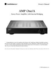
<strong>ATC6DM</strong><br />
Specifications<br />
Dual Voice Coil Woofer<br />
Tweeters<br />
Frequency Response<br />
Impedance<br />
Sensitivity<br />
Power Capacity<br />
Outer Dimension<br />
Cut Out Dimension<br />
Mounting depth<br />
New Construction Bracket<br />
6.5” Mica Filled Poly Cone with Butyl Rubber Surround<br />
Dual 19mm ferrofluid Cooled<br />
50Hz to 20kHz<br />
16 ohms (mono application) / 8 ohms (stereo application)<br />
86dB/89dB, 2.83v @ 1m<br />
10 to 175 Watts<br />
9” (229mm) diameter<br />
7.75” (197mm) diameter<br />
3.38” (86mm)<br />
Order Part Number: NCBC6<br />
Two Year Limited Warranty<br />
Phoenix Gold Innovative Home, a division of Peak Audio Group, warrants this product against defects in materials and<br />
workmanship for a limited period of time. For a period of two (2) years from date of original purchase, we<br />
will repair or replace the product, at our option, without charge for parts. Customer must pay for all labor<br />
charges associated with the removal and re-installation of speakers for the limited period and all parts and<br />
labor charges after the limited warranty period expires. The limited warranty period for factory refurbished<br />
products expires after ninety (90) days from date of original purchase. This limited warranty applies only to<br />
purchases from authorized Phoenix Gold Innovative Home Retailers or Distributors. This limited warranty is<br />
extended only to the original purchaser and is valid only to consumers in the United States.<br />
Consumers are required to provide a copy of the original sales invoice from an authorized Phoenix Gold<br />
Innovative Home Retailer or Distributor when making a claim against this limited warranty. This limited<br />
warranty only covers failures due to defects in materials or workmanship that occur during normal use. It<br />
does not cover failures resulting from accident, fire, flood, misuse, abuse, neglect, mishandling,<br />
misapplication, alteration, faulty installation, modification, service by anyone other than Phoenix Gold<br />
Innovative Home, or damage that is attributable to Acts of God. It does not cover costs of transportation to<br />
Phoenix Gold Innovative Home or damage in transit. The customer should return their defective product,<br />
freight prepaid and insured, to Phoenix Gold Innovative Home only after receiving a Return Authorization.<br />
Repair or replacement under the terms of this warranty does not extend the term of this warranty. Should a<br />
product prove to be defective in workmanship or material, the consumer's sole remedies will be repair or<br />
replacement as provided under the terms of this warranty. If the defective product is discontinued Phoenix<br />
Gold Innovative Home may replace the product with an equivalent or superior product at its option. Any cost<br />
of re-installation or repair of wall or ceiling surface is the sole responsibility of the customer and that cost<br />
shall not be the responsibility of Phoenix Gold Innovative Home. Under no circumstances shall Phoenix<br />
Gold Innovative Home be liable for loss or damage, direct, consequential or incidental, arising out of the<br />
use of or inability to use the product. There are no express warranties other than described above.<br />
INNOVATIVE HOME<br />
13970 SW 72nd Avenue Portland, Oregon 97223<br />
503.914.4688 Fax: 503.746.5224 Support: 877.715.5439<br />
www.audiosource.net support@audiosource.net<br />
4