ATC6DM Manual.pdf - AudioSource
ATC6DM Manual.pdf - AudioSource
ATC6DM Manual.pdf - AudioSource

You also want an ePaper? Increase the reach of your titles
YUMPU automatically turns print PDFs into web optimized ePapers that Google loves.
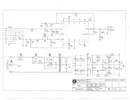
After selecting the mounting location, mark the hole to<br />
be cut out. A template is provided in the speaker box.<br />
Locate and align the template, then mark with pencil<br />
on the ceiling surface. If you are unsure whether there<br />
are obstructions behind the ceiling surface where the<br />
speakers are to be mounted, cut a small hole in the<br />
center of your marked mounting location. Holding your<br />
drywall saw at a 45 degree angle (See Figure 1), cut a<br />
square hole that you can use to locate any obstructions,<br />
should they exist.<br />
ROOM<br />
Figure 1<br />
The 45 degree wedge shape of the removed surfacing<br />
material will make replacement, if necessary, a much<br />
easier task and yield a better finish when patching the<br />
work.<br />
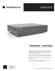
Once it has been determined that there are no obstructions,<br />
cut the hole to mount the speaker using the drywall<br />
saw at a 90 degree angle to the ceiling surface. Cover<br />
the raw edges of the wallboard with masking tape<br />
(See Figure 2). This will prevent the back pressure of the<br />
speaker from blowing loose gypsum dust out and onto<br />
the painted ceiling surface after installation. Do not allow<br />
the tape to extend more than 1/4” beyond the edge of the<br />
hole into the room. The frame of the speaker will cover<br />
and hide the tape.<br />
Masking T.ape<br />
ROOM<br />
Figure 2<br />
Next run your speaker wire to your speaker locations.<br />
A UL rated CL3 speaker wire is recommended when<br />
running wire inside your walls. In many areas it may<br />
be required by code. When running your speaker wire<br />
you should avoid having the speaker wire run parallel<br />
to the 120V power lines to avert picking up hum and<br />
interference from the power service. If the speaker<br />
wire needs to cross a 120V power line at a right angle<br />
this is acceptable and will not create a problem.<br />
If you are uncomfortable with running the speaker wire<br />
yourself in existing construction, it is recommended that<br />
you retain a qualified custom home installation specialist<br />
or electrician.<br />
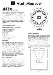
Installing the Speaker<br />
Installation Tip! To further enhance the performance<br />
of your ATC-DM speaker, the ceiling joist cavity where<br />
you plan to place your speaker can be stuffed with a<br />
generous quantity of fiberglass insulation. Stuff the area<br />
in front of and behind the speaker opening with 6” thick<br />
insulation to a depth of approximately 2 feet beginning<br />
1 foot in front and 1 foot behind the speaker opening. If<br />
the insulation is foil or paper backed, face the backing<br />
away from the ATC-DM speaker. The addition of this<br />
insulation will help prevent unwanted transfer of sound<br />
into the otherwise large and resonant cavity of the uninsulated<br />
ceiling.<br />
2<br />
Grill Removal for Installation<br />
CAUTION! The grill is held in place by contact pressure<br />
around the edges where it attaches to the speaker frame.<br />
To avoid difficulty reinstalling the grill, care should be taken<br />
to not distort its shape<br />
while removing it.<br />
1/4"(6mm)<br />
While looking at the rear<br />
of the speaker assembly,<br />
rotate two of the adjacent<br />
mounting clamps outward<br />
and then evenly press them<br />
towards the grill. The clamp<br />
screws contact the inner<br />
surface of the grill, pushing<br />
it gently out of its mounting<br />
groove (Figure 3). Only lift<br />
the grill 1/4" (6mm) at this<br />
location. Next use the other<br />
mounting clamps to further<br />
loosen the grill. Use care to<br />
not distort the grill shape.<br />
Connecting the Speaker<br />
Figure 3<br />
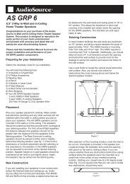
It is now time to connect the speaker wire to the speaker.<br />
Your speaker wire is usually coded to identify each<br />
conductor as either positive or negative. This can be<br />
by color coding, or one conductor may have a printed<br />
marking or at least a rib along one edge that you will not<br />
find on the other. Identify which type of polarity coding<br />
that your wire is using. You must carefully observe that<br />
the positive terminal of the speaker output on your<br />
amplifier is connected to the positive terminal of the<br />
ATC-DM speaker. Likewise, the negative terminal of the<br />
amplifier’s speaker output should be connected to the<br />
negative terminal of the ATC-DM speaker (Figure 4).<br />
(+) Amp<br />
(-) Amp<br />
(-) Amp<br />
(+) Amp<br />
(R)<br />
(L)<br />
(+) Amp (R or L)<br />
(-) Amp<br />
Figure 4<br />
Right and Left<br />
Channels are<br />
Both Connected<br />
(Summed<br />
Mono Speaker)<br />
Only Right or Left<br />
Channel is<br />
Connected<br />
(Conventional<br />
Speaker)<br />
Caution! If the ATC-DM is set to 8Ω with two<br />
amplifier channels connected, amplifier damage<br />
will occur.