Q Calculations of L-C Circuits and Transmission Lines ... - Ve2azx.net
Q Calculations of L-C Circuits and Transmission Lines ... - Ve2azx.net
Q Calculations of L-C Circuits and Transmission Lines ... - Ve2azx.net

Create successful ePaper yourself
Turn your PDF publications into a flip-book with our unique Google optimized e-Paper software.
R s <strong>and</strong> X <strong>and</strong> are the real <strong>and</strong> imaginary components<br />
<strong>of</strong> the RLC circuit impedance Z <strong>and</strong><br />
ω= 2πf.<br />
Equation 2 may be simplified as:<br />
Fr<br />
L<br />
Qa<br />
(Eq 3)<br />
Rs<br />
f C<br />
where Q a is the Q factor below the resonant<br />
frequency F r <strong>and</strong> f is the frequency at which<br />
Q a is calculated.<br />
The resonant frequency may be expressed<br />
as:<br />
1<br />
F r<br />
(Eq 4)<br />
2 LC<br />
After substituting Equation 4 into<br />
Equation 3, we get:<br />
1<br />
Qa<br />
(Eq 5)<br />
2 fCRs<br />
This equation is valid at resonance <strong>and</strong><br />
below.<br />
Equation 5 simply represents the ratio <strong>of</strong><br />
the capacitive reactance to the series<br />
resistance, R s .<br />
An equation similar to Equation 2 may<br />
be used above resonance:<br />
dX<br />
X <br />
Q<br />
d<br />
b<br />
<br />
(Eq 6)<br />
2 Rs<br />
The sign <strong>of</strong> the first term <strong>of</strong> the<br />
numerator, X, is now positive. As before,<br />
Equation 6 may be simplified:<br />
f L<br />
Qb<br />
(Eq 7)<br />
Rs<br />
Fr<br />
C<br />
After substituting Equation 4 into<br />
Equation 7, we get:<br />
2 fL<br />
Q (Eq 8)<br />
Rs<br />
This equation is valid at resonance <strong>and</strong><br />
above.<br />
Equation 8 simply represents the ratio <strong>of</strong><br />
inductive reactance to the series resistance,<br />
R s .<br />
Equations 2 <strong>and</strong> 6 may be combined by<br />
taking the absolute value <strong>of</strong> X in the first<br />
numerator term. Equation 9 gives the Q<br />
factor <strong>of</strong> a series RLC circuit, below <strong>and</strong><br />
above the resonant frequency.<br />
dX<br />
X <br />
Q <br />
d <br />
(Eq 9)<br />
2 R s<br />
This equation is for computing the Q<br />
factor above <strong>and</strong> below series resonance.<br />
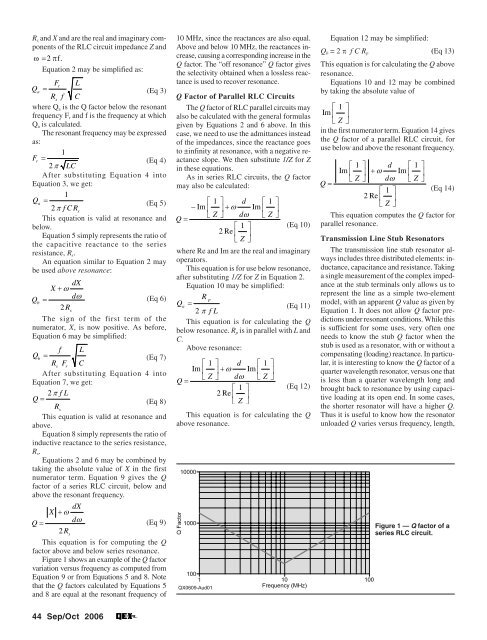
Figure 1 shows an example <strong>of</strong> the Q factor<br />
variation versus frequency as computed from<br />
Equation 9 or from Equations 5 <strong>and</strong> 8. Note<br />
that the Q factors calculated by Equations 5<br />
<strong>and</strong> 8 are equal at the resonant frequency <strong>of</strong><br />
10 MHz, since the reactances are also equal.<br />
Above <strong>and</strong> below 10 MHz, the reactances increase,<br />
causing a corresponding increase in the<br />
Q factor. The “<strong>of</strong>f resonance” Q factor gives<br />
the selectivity obtained when a lossless reactance<br />
is used to recover resonance.<br />
Q Factor <strong>of</strong> Parallel RLC <strong>Circuits</strong><br />
The Q factor <strong>of</strong> RLC parallel circuits may<br />
also be calculated with the general formulas<br />
given by Equations 2 <strong>and</strong> 6 above. In this<br />
case, we need to use the admittances instead<br />
<strong>of</strong> the impedances, since the reactance goes<br />
to ±infinity at resonance, with a negative reactance<br />
slope. We then substitute 1/Z for Z<br />
in these equations.<br />
As in series RLC circuits, the Q factor<br />
may also be calculated:<br />
1 d 1 <br />
Im<br />
<br />
Im <br />
Z d Z <br />
Q <br />
1 <br />
2Re<br />
<br />
Z <br />
(Eq 10)<br />
where Re <strong>and</strong> Im are the real <strong>and</strong> imaginary<br />
operators.<br />
This equation is for use below resonance,<br />
after substituting 1/Z for Z in Equation 2.<br />
Equation 10 may be simplified:<br />
R<br />
p<br />
Qa<br />
(Eq 11)<br />
2 fL<br />
This equation is for calculating the Q<br />
below resonance. R p is in parallel with L <strong>and</strong><br />
C.<br />
Above resonance:<br />
1 d 1 <br />
Im <br />
Im <br />
Z d Z <br />
Q <br />
1 <br />
2Re<br />
<br />
Z <br />
(Eq 12)<br />
This equation is for calculating the Q<br />
above resonance.<br />
Equation 12 may be simplified:<br />
Q b = 2 π f C R p (Eq 13)<br />
This equation is for calculating the Q above<br />
resonance.<br />
Equations 10 <strong>and</strong> 12 may be combined<br />
by taking the absolute value <strong>of</strong><br />
1<br />
Im <br />
<br />
<br />
<br />
Z <br />
in the first numerator term. Equation 14 gives<br />
the Q factor <strong>of</strong> a parallel RLC circuit, for<br />
use below <strong>and</strong> above the resonant frequency.<br />
1 d 1 <br />
Im Im <br />
Z d Z <br />
Q <br />
1 (Eq 14)<br />
2Re<br />
<br />
Z <br />
This equation computes the Q factor for<br />
parallel resonance.<br />
<strong>Transmission</strong> Line Stub Resonators<br />
The transmission line stub resonator always<br />
includes three distributed elements: inductance,<br />
capacitance <strong>and</strong> resistance. Taking<br />
a single measurement <strong>of</strong> the complex impedance<br />
at the stub terminals only allows us to<br />
represent the line as a simple two-element<br />
model, with an apparent Q value as given by<br />
Equation 1. It does not allow Q factor predictions<br />
under resonant conditions. While this<br />
is sufficient for some uses, very <strong>of</strong>ten one<br />
needs to know the stub Q factor when the<br />
stub is used as a resonator, with or without a<br />
compensating (loading) reactance. In particular,<br />
it is interesting to know the Q factor <strong>of</strong> a<br />
quarter wavelength resonator, versus one that<br />
is less than a quarter wavelength long <strong>and</strong><br />
brought back to resonance by using capacitive<br />
loading at its open end. In some cases,<br />
the shorter resonator will have a higher Q.<br />
Thus it is useful to know how the resonator<br />
unloaded Q varies versus frequency, length,<br />
Figure 1 — Q factor <strong>of</strong> a<br />
series RLC circuit.<br />
44 Sep/Oct 2006