Rad-Hard 32-bit SPARC V8 Processor AT697E Errata Sheet - DIT
Rad-Hard 32-bit SPARC V8 Processor AT697E Errata Sheet - DIT
Rad-Hard 32-bit SPARC V8 Processor AT697E Errata Sheet - DIT

You also want an ePaper? Increase the reach of your titles
YUMPU automatically turns print PDFs into web optimized ePapers that Google loves.
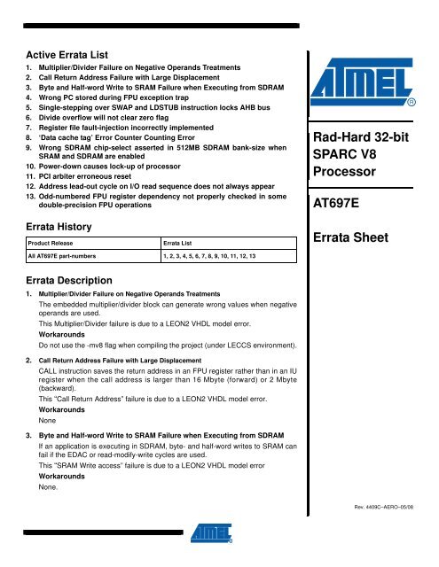
Active <strong>Errata</strong> List<br />
1. Multiplier/Divider Failure on Negative Operands Treatments<br />
2. Call Return Address Failure with Large Displacement<br />
3. Byte and Half-word Write to SRAM Failure when Executing from SDRAM<br />
4. Wrong PC stored during FPU exception trap<br />
5. Single-stepping over SWAP and LDSTUB instruction locks AHB bus<br />
6. Divide overflow will not clear zero flag<br />
7. Register file fault-injection incorrectly implemented<br />
8. ‘Data cache tag’ Error Counter Counting Error<br />
9. Wrong SDRAM chip-select asserted in 512MB SDRAM bank-size when<br />
SRAM and SDRAM are enabled<br />
10. Power-down causes lock-up of processor<br />
11. PCI ar<strong>bit</strong>er erroneous reset<br />
12. Address lead-out cycle on I/O read sequence does not always appear<br />
13. Odd-numbered FPU register dependency not properly checked in some<br />
double-precision FPU operations<br />
<strong>Rad</strong>-<strong>Hard</strong> <strong>32</strong>-<strong>bit</strong><br />
<strong>SPARC</strong> <strong>V8</strong><br />
<strong>Processor</strong><br />
<strong>AT697E</strong><br />
<strong>Errata</strong> History<br />
Product Release<br />
<strong>Errata</strong> List<br />
<strong>Errata</strong> <strong>Sheet</strong><br />
All <strong>AT697E</strong> part-numbers 1, 2, 3, 4, 5, 6, 7, 8, 9, 10, 11, 12, 13<br />
<strong>Errata</strong> Description<br />
1. Multiplier/Divider Failure on Negative Operands Treatments<br />
The embedded multiplier/divider block can generate wrong values when negative<br />
operands are used.<br />
This Multiplier/Divider failure is due to a LEON2 VHDL model error.<br />
Workarounds<br />
Do not use the -mv8 flag when compiling the project (under LECCS environment).<br />
2. Call Return Address Failure with Large Displacement<br />
CALL instruction saves the return address in an FPU register rather than in an IU<br />
register when the call address is larger than 16 Mbyte (forward) or 2 Mbyte<br />
(backward).<br />
This “Call Return Address” failure is due to a LEON2 VHDL model error.<br />
Workarounds<br />
None<br />
3. Byte and Half-word Write to SRAM Failure when Executing from SDRAM<br />
If an application is executing in SDRAM, byte- and half-word writes to SRAM can<br />
fail if the EDAC or read-modify-write cycles are used.<br />
This “SRAM Write access” failure is due to a LEON2 VHDL model error<br />
Workarounds<br />
None.<br />
Rev. 4409C–AERO–05/08
4. Wrong PC stored during FPU exception trap<br />
When a trap is taken by the processor, the program counter (PC) is stored into %l1 of the trap window and the next program<br />
counter (nPC) is stored into %l2. This operation works correctly for all traps except FPU exception (trap type<br />
0x08). During FPU exception, the nPC is erroneously stored into both %l1 and %l2. This means that the exception handler<br />
can not return and re-execute the trapped FPU instruction. During normal operation, this is not a problem since reexecuting<br />
the trapped instruction would just cause the instruction to trap again.<br />
Workarounds<br />
None<br />
5. Single-stepping over SWAP and LDSTUB instruction locks AHB bus<br />
During a debug session using the debug support unit (DSU), it is possible to perform singlestepping. If an attempt to<br />
single-step a SWAP or LDSTUB instruction is made, the AHB bus will be locked and further debugging will be impossible.<br />
The reason for this behaviour is that SWAP and LDSTUB instruction perform a read-modify-write cycle which locks<br />
the AHB bus to insure atomicity. When such an instruction is single-stepped, the lock signal will be kept active even<br />
after the processor enters debug mode, thereby preventing further bus ar<strong>bit</strong>ration. Since the communications with the<br />
DSU is done over the AHB bus, further debugging is impossible and the device is in principle dead-locked. This state<br />
can only be exited by deasserting the DSUEN signal (resuming execution) or asserting the RESET signal.<br />
Workarounds<br />
None<br />
6. Divide overflow will not clear zero flag<br />
The divide instructions SDIVCC and UDIVCC set the integer condition codes (negative, overflow and zero) with<br />
respect to the final result. When a divide overflow occurs, a pre-defined non-zero value is returned, the overflow <strong>bit</strong> is<br />
set and the zero <strong>bit</strong> is cleared. However, under certain overflow conditions, the zero <strong>bit</strong> is wrongly set even though the<br />
result is always nonzero.<br />
Workarounds<br />
None<br />
7. Register file fault-injection incorrectly implemented<br />
The LEON2-FT processor has a fault-injection function which allows the insertion of errors into the 7-<strong>bit</strong> EDAC checksum<br />
that protects each word of the register file. When fault-injection is enabled, the EDAC checksums are supposed to<br />
be XORed with the value of the TCB field in the %asr16 register. The fault injection is instead implemented as follows:<br />
– check <strong>bit</strong>s[6:4] of dual-port ram 1 (corresponding to %rs1 operand) are XORed with TCB[2:0]<br />
– check <strong>bit</strong>s[6:4] of dual-port ram 2 (corresponding to %rs2 operand) are XORed with TCB[5:3].<br />
2<br />
<strong>AT697E</strong><br />
4409C–AERO–05/08
<strong>AT697E</strong><br />
Workarounds<br />
Fault-injection is still possible as intended, but the injection software must be aware of the difference <strong>bit</strong> location of the<br />
injected errors. Here is a simple example for the test of a single error in register file %rs1<br />
! 0x<strong>32</strong> =<br />
! register file test enable<br />
! tcb[2:0] = 0x4<br />
! tcb[5:3] = 0x1<br />
mov 0x<strong>32</strong>, %l1<br />
mov %l1, %asr16<br />
! clear %l3<br />
! => write 0x0 to %l3<br />
! forces 0x08 as check<strong>bit</strong> for %l3 (error insertion in %rs1 dual-port ram)<br />
mov %g0, %l3<br />
! disable EDAC test mode<br />
mov %g0, %asr16<br />
! access to %l3 as %rs1 operand<br />
! => single error detection and correction<br />
add %l3,%l2,%l1<br />
8. ‘Data cache tag’ Error Counter Counting Error<br />
The data tag error counter doesn’t show the correct number of errors.<br />
If a data tag error is detected on a write cycle, the data cache is not updated but the tag error is counted. Since the tag<br />
is not written the error remains, and on sub-sequent writes to the same address the error will be counted again.<br />
It is also possible that a tag error occurs on the same address offset as an on-chip register. A tag error will then be<br />
reported every time the register is accessed, since the access is not cacheable and the tag will not be written. If the<br />
application software does not use this particular location of the cache, the error will never be removed but continously<br />
reported.<br />
Workarounds<br />
Applications that do not use all locations of the cache should monitor the error counters and perform a flush operation<br />
when an error has been registered.<br />
9. Wrong SDRAM chip-select asserted in 512MB SDRAM bank-size when SRAM and SDRAM are enabled<br />
If the SRAM and the SDRAM are enabled in MCFG2 (the SDRAM is mapped starting at address 0x60000000) with an<br />
SDRAM bank size of 512 Mbytes, then the SDCS*[1] signal will be asserted instead of the SDCS*[0] signal when<br />
accessing the SDRAM.<br />
This error does not occur when the SDRAM bank size is smaller than 512 Mbytes, or when the SRAM is disabled (the<br />
SDRAM is mapped starting at address 0x40000000).<br />
Workarounds<br />
If a bank size of 512 Mbyte is used with the SRAM and the SDRAM enabled (the SDRAM is mapped starting at<br />
address 0x60000000), connect SDCS*[1] to the chip-select pin of the SDRAM device.<br />
10. Power-down causes lock-up of processor<br />
If an asynchronous interrupt occurs between the store/load sequence of power-down, the processor might enter<br />
power-down inside the interrupt handler. Since the traps are then disabled, the processor will not exit the power-down<br />
mode on the next interrupt and hang infinitely.<br />
Workarounds<br />
None - Do not use the power-down functionality.<br />
4409C–AERO–05/08<br />
3
11. PCI ar<strong>bit</strong>er erroneous reset<br />
The AHB clock domain in the PCI ar<strong>bit</strong>er is erroneously reset by the PCI reset, while the PCI clock domain is reset by<br />
the AHB reset. If a PCI reset is issued, then the PCI ar<strong>bit</strong>er registers will be reset to their default value.<br />
Workarounds<br />
Assert the PCI reset simultaneously with the processor reset to avoid possible side-effects.<br />
12. Address lead-out cycle on I/O read sequence does not always appear<br />
During an I/O read sequence, the address is specified to be stable one clock cycle after the de-assertion of the IOS*[x]<br />
I/O select signal. Under certain conditions, the address is de-asserted at the same clock edge as the I/O select signal.<br />
The occurence of the missing address lead-out cycle cannot be (easily) predicted.<br />
Workarounds<br />
Design the external I/O devices to operate correctly without the need for an address lead-out cycle.<br />
13. Odd-numbered FPU register dependency not properly checked in some double-precision FPU operations<br />
Data dependency is not properly checked between a load singleword floating-point instruction (LDF) involving an oddnumbered<br />
floating-point register as a destination of the load and an immediately following double-precision floatingpoint<br />
instruction (FADDd, FSUBd, FMULd, FDIVd or FSQRTd) that satisfies all of the following conditions:<br />
• the odd-numbered floating-point register is used as (part of) a source operand<br />
• the destination floating-point register is also a source operand<br />
• in an FSUBd or FDIVd, the two source operands are different registers<br />
In this case, the final result of the double-precision floating-point instruction will be wrong.<br />
Other double-precision floating-point instructions (FCMPd, FCMPEd, FdTOi and FdTOs) are not affected by this issue<br />
and will operate as expected.<br />
The error case appears when any of the six following sequences of instructions is present (n in [0:31], x and y as different<br />
even numbers in [0:30]):<br />
– Case 1:<br />
LD [%r n ], %f x+1<br />
– Case 2:<br />
FPOPd (1) %f x , %f y , %f x<br />
LD [%r n ], %f x+1<br />
– Case 3:<br />
FPOPd (1) %f y , %f x , %f x<br />
LD [%r n ], %f x+1<br />
– Case 4:<br />
FPOPd (1) %f x , %f y , %f y<br />
LD [%r n ], %f x+1<br />
– Case 5:<br />
FPOPd (1) %f y , %f x , %f y<br />
LD [%r n ], %f x+1<br />
– Case 6:<br />
FPOPd (2) %f x , %f x , %f x<br />
LD [%r n ], %f x+1<br />
SQRTd %f x , %f x<br />
Notes:<br />
1. FPOPd is one of FADDd, FSUBd, FMULd or FDIVd.<br />
2. FPOPd is one of FADDd or FMULd (FSUBd and FDIVd operate as expected).<br />
4<br />
<strong>AT697E</strong><br />
4409C–AERO–05/08
<strong>AT697E</strong><br />
Workarounds<br />
If direct control over assembly language is possible, simply insert a NOP before the double-precision floating-point<br />
instruction (case 1 to 6):<br />
LD [%r n ], %f x+1<br />
NOP<br />
FPOPd <br />
If direct control over assembly language is not possible (high-level programming language such as C), checking the<br />
<strong>SPARC</strong> binary code against any of the six above mentioned faulty sequences of instructions shall be done using the<br />
code-checker program provided by Atmel (search for doc7787 on Atmel web site).<br />
Although there is a very low likelihood of occurrence with high-level programming languages, customers facing this<br />
problem should contact the <strong>SPARC</strong> hotline (sparc-applab.hotline@nto.atmel.com).<br />
4409C–AERO–05/08<br />
5
Headquarters<br />
International<br />
Atmel Corporation<br />
2<strong>32</strong>5 Orchard Parkway<br />
San Jose, CA 95131<br />
USA<br />
Tel: 1(408) 441-0311<br />
Fax: 1(408) 487-2600<br />
Atmel Asia<br />
Room 1219<br />
Chinachem Golden Plaza<br />
77 Mody Road Tsimshatsui<br />
East Kowloon<br />
Hong Kong<br />
Tel: (852) 2721-9778<br />
Fax: (852) 2722-1369<br />
Atmel Europe<br />
Le Krebs<br />
8, Rue Jean-Pierre Timbaud<br />
BP 309<br />
78054 Saint-Quentin-en-<br />
Yvelines Cedex<br />
France<br />
Tel: (33) 1-30-60-70-00<br />
Fax: (33) 1-30-60-71-11<br />
Atmel Japan<br />
9F, Tonetsu Shinkawa Bldg.<br />
1-24-8 Shinkawa<br />
Chuo-ku, Tokyo 104-0033<br />
Japan<br />
Tel: (81) 3-3523-3551<br />
Fax: (81) 3-3523-7581<br />
Product Contact<br />
Web Site<br />
www.atmel.com<br />
Technical Support<br />
aerospace@nto.atmel.com<br />
Sales Contact<br />
www.atmel.com/contacts<br />
Literature Requests<br />
www.atmel.com/literature<br />
Disclaimer: The information in this document is provided in connection with Atmel products. No license, express or implied, by estoppel or otherwise, to any<br />
intellectual property right is granted by this document or in connection with the sale of Atmel products. EXCEPT AS SET FORTH IN ATMEL’S TERMS AND CONDI-<br />
TIONS OF SALE LOCATED ON ATMEL’S WEB SITE, ATMEL ASSUMES NO LIABILITY WHATSOEVER AND DISCLAIMS ANY EXPRESS, IMPLIED OR STATUTORY<br />
WARRANTY RELATING TO ITS PRODUCTS INCLUDING, BUT NOT LIMITED TO, THE IMPLIED WARRANTY OF MERCHANTABILITY, FITNESS FOR A PARTICULAR<br />
PURPOSE, OR NON-INFRINGEMENT. IN NO EVENT SHALL ATMEL BE LIABLE FOR ANY DIRECT, INDIRECT, CONSEQUENTIAL, PUNITIVE, SPECIAL OR INCIDEN-<br />
TAL DAMAGES (INCLUDING, WITHOUT LIMITATION, DAMAGES FOR LOSS OF PROFITS, BUSINESS INTERRUPTION, OR LOSS OF INFORMATION) ARISING OUT<br />
OF THE USE OR INABILITY TO USE THIS DOCUMENT, EVEN IF ATMEL HAS BEEN ADVISED OF THE POSSIBILITY OF SUCH DAMAGES. Atmel makes no<br />
representations or warranties with respect to the accuracy or completeness of the contents of this document and reserves the right to make changes to specifications<br />
and product descriptions at any time without notice. Atmel does not make any commitment to update the information contained herein. Unless specifically provided<br />
otherwise, Atmel products are not suitable for, and shall not be used in, automotive applications. Atmel’s products are not intended, authorized, or warranted for use<br />
as components in applications intended to support or sustain life.<br />
© 2008 Atmel Corporation. All rights reserved. Atmel ® , logo and combinations thereof, and others are registered trademarks or trademarks of<br />
Atmel Corporation or its subsidiaries. Other terms and product names may be trademarks of others.<br />
4409C–AERO–05/08